Table of Contents
Advertisement
Quick Links
Advertisement
Table of Contents

Related Manuals for ABB PVS980-CS


Summary of Contents for ABB PVS980-CS
- Page 1 — ABB SOLAR INVERTERS PVS980-CS compact skid Hardware manual...
- Page 3 PVS980-CS compact skid Hardware manual Table of contents 1. Safety instructions 5. Mechanical installation 6. Electrical installation 8. Start-up and operation © 2019 ABB Oy. All Rights Reserved. 3AES-PVS980-CS-00-MA01 Rev A EFFECTIVE: 2019-10-31...
-
Page 5: Table Of Contents
Table of contents 5 Table of contents 1 Safety instructions Contents of this chapter ................Use of warnings ................... Allowed usage ..................Safe installation, start-up and maintenance ..........General safety instructions ..............Working areas ................. Personal protective equipment (PPE) ............PPE safety equipment .............. - Page 6 6 Table of contents Storing ....................Conditions for using desiccant bags ............Lifting ....................Tools used for lifting ................Lifting instructions ................Transporting ..................Incoming inspection at arrival ............... Unloading ..................Tools used for unloading ..............Pre-requisite ................... Unloading instructions ................ 5 Mechanical installation Contents of this chapter ................
- Page 7 11 Maintenance of external hinges and locks Tools ....................Lubricating the external hinges and locks ..........Procedure ..................12 Technical data Contents of this chapter ................Technical data and types: PVS980-CS ............13 Drawings Contents of this chapter ................List of technical drawings ................ Further information...
-
Page 9: Safety Instructions
Contents of this chapter This chapter presents the use of warnings in the manual and gives instructions for safe installation, start-up, use and maintenance of the PVS980-CS compact skid. Use of warnings Warnings caution you about conditions which can result in serious injury or death and/or damage to the equipment, and advise on how to avoid the danger. -
Page 10: Allowed Usage
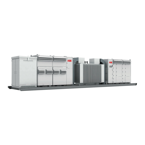
Allowed usage • The PVS980-CS is a compact skid containing: two outdoor 1500 VDC ABB central inverters, an ABB oil immersed MV transformer, MV switchgear, a monitoring system and DC connections. The skid connects a PV power plant to a medium voltage grid. -
Page 11: Working Areas
Safety instructions 11 ■ Working areas • MV Transformer Area • MV Switchgear Area • Inverter Area • Auxiliary Service Area Each work area has separate safety instructions. ■ Personal protective equipment (PPE) • Perform any operation on the equipment with suitable work clothes and instruments. PPE safety equipment (page 11). -
Page 12: Disconnecting The Mv Switchgear From Power Supply
12 Safety instructions 8. Check that the MV transformer is dead (high voltage terminals, low voltage terminals, any auxiliary power, and instrumentation). Use an appropriate high voltage tester only for the high voltage side, and a voltage detector with suitable testing heads for the low voltage side. -
Page 13: Disconnecting The Inverter From All Possible Sources
Safety instructions 13 3. Disconnect and isolate. (Not all disconnectors provide sufficient isolation against voltage surges.). See instructions in section, Disconnecting the inverter from all possible sources (page 13). 4. Protect any other energized parts in the work location against contact. 5. -
Page 14: Disconnecting The Mv Switchgear (V-Module)
14 Safety instructions 5. After disconnecting the inverter, wait for at least five minutes to let the capacitors discharge. Disconnecting the MV switchgear (V-module) To disconnect the MV switchgear (V-module), follow the below steps: 1. Open the V-module breaker, lock and add warning notices. 2. - Page 15 If the Start switch is in ON position, and the Start command is active, the inverter starts immediately after a fault reset. For more information, see PVS980 central inverters firmware manual (3AXD50000026271 [EN]). • Use the start delay when you start the PVS980-CS for the first time to let you move away.
-
Page 17: Introduction To This Manual
This chapter provides information about the manual such as applicability, target audience and contents. It also lists the related documents. Applicability This manual is applicable to PVS980-CS (compact skid). Target audience This manual is intended for persons who transport, store, plan the installation, install, commission and maintain the compact skid. -
Page 18: Terms And Abbreviations
MV transformers to do: not available in library Terms and abbreviations Term/ Description Abbreviation Alternating current Construction of ABB SafeRing MV switchgear Compact skid Construction of MV switchgear Direct current Low voltage (50...1000 V AC) LVRT Low voltage ride-through Medium voltage (1...35 kV) Personal protective equipment Sulfur hexafluoride (this gas type is used in MV switchgear). -
Page 19: Hardware Description
This chapter provides an overview of the PVS980-CS (compact skid). It also includes layout, type designation label and type designation information. Product overview The PVS980-CS is a skid-based solution that connects a PV power plant to a medium voltage power grid. The solution is constructed around a skid house that contains: •... -
Page 20: Layout Drawing
20 Hardware description Layout drawing This section describes the working areas and main components of the PVS980-CS. For more information, see drawing, 3AES-PVS980-CS-30-DW01. Working areas and main components MV switchgear area. For more information, see section MV switchgear (page 24). -
Page 21: Main Components
Hardware description 21 ■ Main components MV switchgear Lead-through holes for power grid cabling and terminal for external earthing electrode (in base plate, at the end of MV switchgear area) Cooling air inlet Cooling air outlet Lead-through holes for DC cabling from solar generator. Terminal for the external DC earthing. Lead-through holes for AC cabling from inverters to MV transformer. -
Page 22: Ac Cabinet Components
22 Hardware description ■ AC cabinet components Inverter inputs. For more information, see section Inverter inputs. Auxiliary service board. For more information, see section Auxiliary service board (page 22). ■ Auxiliary service board The figure below describes the components of a standard auxiliary service board. Additional components and customization are[ included in the project specific documentation. - Page 23 Hardware description 23 Downstream circuit breaker for auxiliary service transformer protection Torch light and charger Auxiliary service board circuit breakers and differential protections Grounding busbar Terminals block...
-
Page 24: Mv Switchgear
24 Hardware description ■ MV switchgear The station is always equipped with ABB SafeRing MV switchgear. Type CV is used as the standard and consists of two modules: • C uses a double cable bushing configuration to connect to: 1. The grid-side module with grid cable terminals and a disconnecting and earthing switch. -
Page 25: Mv Transformer
Hardware description 25 ■ MV transformer See MV transformer manual (1LTR954400-1). ■ Inverter For information on the inverter, see: • PVS980 central inverter hardware manual (3AXD50000026013 [EN]) • PVS980 central inverters commissioning and maintenance manual (3AXD50000046782 [EN]) • PVS980 central inverters firmware manual (3AXD50000026271 [EN]). -
Page 26: Main Circuit Diagram
The general single-line diagram depends on the configuration and options of the unit as well as the configuration of the inverter group. The table below describes the baseline configuration. See also, single line diagram 3AES-PVS980-CS-01-DW01 (List of technical drawings (page 67)). -
Page 27: Type Designation Label
Hardware description 27 Type designation label The figure below shows an example of the type designation label. The label contains the basic data of the unit. It is located inside the AC cabinet in the door to access the Auxiliary service board. -
Page 28: Type Designation Key
The following table describes the fields of the basic code and the option code. Refer to the items of figure in Type designation label. Example: PVS980-CS - XXXX - Y - + Options Item Description PVS980 = Inverter mode CS (Compact skid) = Station type... -
Page 29: Storing, Lifting And Transporting
Storing, lifting and transporting 29 Storing, lifting and transporting Contents of this chapter This chapter provides instructions for storing, lifting and transporting the PVS980-CS (compact skid). WARNING! Inspect carefully the container before performing any activity. Verify that the compact skid has no protuberance, lack of rings, or any general poor condition. -
Page 30: Storing
30 Storing, lifting and transporting Storing WARNING! To prevent damage to the compact skid, keep the delivery packaging and protection canvas on until you install it. • Always store the compact skid in upright position. • If removing the compact skid from protective packaging and if condensation is possible in the storage area, follow the below conditions: •... -
Page 31: Lifting
Storing, lifting and transporting 31 Lifting WARNING! Inspect the container before any activity. Make sure that the container has no protuberance, enough rings and is in good condition. Ignorance of this message can cause physical injury, death or damage to the equipment. Before lifting the compact skid, follow these instructions. -
Page 32: Lifting Instructions
32 Storing, lifting and transporting ■ Lifting instructions 1. Place the two spreaders across the compact skid. See locations marked in below figure. 2. Attach the sling or chains to the base structure fastening point. 3. Connect the slings to the spreaders as shown in the below figures. 4. -
Page 33: Transporting
■ Incoming inspection at arrival • Visually check for any potential transportation damage(s). If any damages found, mark and record them and immediately inform your local ABB representative or your ABB sales contact. • Repair any damaged paint. See section, Maintenance of painted surfaces (page 57). -
Page 34: Unloading
Two slings of eight tons. Minimum five meters. ■ Pre-requisite Follow the below instructions before you start unloading the PVS980-CS received in a 40 ft HC container: 1. Protect the corners of the compact skid against shock. 2. Make sure that the terrain is level and sturdy. Consider that the compact skid has an approximate weight of 15 tons. -
Page 35: Unloading Instructions
Storing, lifting and transporting 35 ■ Unloading instructions 1. Align the guide platforms to the wheels trajectory. 2. Make sure that the guide platforms are leveled to the container floor. 3. Connect the belly chains to the fastening points in the skid profile. 4. - Page 36 36 Storing, lifting and transporting 5. Slowly and carefully pull the compact skid out of the container using the forklift. The forklift must be perfectly aligned to the compact skid, so that the station does not touch the container walls. Optional: Pull the compact skid until connection with spreader and crane is possible.
-
Page 37: Mechanical Installation
Mechanical installation Contents of this chapter This chapter describes the mechanical installation of the PVS980-CS (compact skid) and gives general instructions on how to select the location and guidelines to build the foundation for the compact skid. Obey all local regulations. -
Page 38: Foundation Guidelines
WARNING! The pit for the foundation and the foundation must be designed by an experienced civil work engineer. Obey all local rules and regulations. ABB is not responsible for the design of the foundation. For information on the MVS dimensions and footprint, see drawing 3AES-PVS980-CS-30-DW02. -
Page 39: Fastening The Compact Skid
WARNING! Do not fasten the compact skid by electric welding, because the welding circuit can damage electronic circuits and integrity of the station. ABB does not assume any liability for damages caused by electric welding. To fasten the compact skid to the foundation, use the supplied attachment brackets (see figure below). - Page 40 Make sure that anything planted near the inverter does not discharge dust or seeds that can affect the cooling air flow. ■ Unpacking To prevent any damage to the compact skid, perform the unpacking as late as possible before the installation. For the permitted operating conditions, see PVS980-CS datasheet.
-
Page 41: Electrical Installation
Electrical installation 41 Electrical installation Contents of this chapter This chapter contains general instructions for earthing and cabling the PVS980-CS (compact skid). Obey all instructions contained in the applicable documentation (such as other hardware manuals) and local regulations. WARNING! Only an authorized electrician is allowed to install the cabling to the compact skid. -
Page 42: Routing The Cables
Construct an earthing electrode for the compact skid. Follow local regulations. Connect the earthing electrode to the terminal located at the base of the compact skid. See drawing 3AES-PVS980-CS-02-DW02. Use joint lubricant to protect the connection point against corrosion. Follow the minimum requirements for the earthing electrode: •... -
Page 43: Protective Earthing (Grounding) Inside The Compact Skid
For more information, see drawing 3AES-PVS980-CS-02-DW02 Measuring the insulation resistance of the cabling Make sure that the insulation resistance of the external power cables are measured according to manufacturer recommendations and local regulations. -
Page 44: Connecting The Power Grid Cabling To The Mv Switchgear
44 Electrical installation 4. Fill the cable trenches and seal the cable entries. See chapter Finalizing the installation (page 45). Connecting the power grid cabling to the MV switchgear See the MV switchgear manual and the wiring diagrams that are delivered with the compact skid. -
Page 45: Finalizing The Installation
Contents of this chapter This chapter contains the general instructions on how to finalize and check the installation of the PVS980-CS (compact skid). Obey all local regulations. WARNING! Only an authorized electrician is permitted to install the cabling to the compact skid. -
Page 46: Landscaping The Station
Check all mechanical operating functions by operating them at least twice. Make sure that the compact skid clearance space is maintained. For more information on the required clearance space, see footprint layout 3AES-PVS980-CS-30-DW02. Examine the paint surface and repair if any damages found. See instructions in section Maintenance of painted surfaces (page 57). -
Page 47: Start-Up And Operation
Start-up and operation 47 Start-up and operation Contents of this chapter This chapter describes the start-up procedure and general operation criteria of the PVS980-CS (compact skid). WARNING! Only an authorized electrician is permitted to start-up and operate the compact skid. Obey the Safety instructions (page 9) and the local safety regulations. -
Page 48: Prerequisite
2. Remove silica gels. See below figure. The locations of silica gels are marked in red Start-up procedure This section describes the procedure to start-up the PVS980-CS (compact skid). WARNING! Only an authorized electrician is permitted to install and perform the start-up procedure. - Page 49 Make sure that the inverters and/or the SCADA powered). system detects the signals. See the project specific circuit diagrams that came with the PVS980-CS. Connecting the PVS980-CS to the power grid Make sure that AC disconnectors of both inverters See PVS980 hardware manual are open. (3AXD50000026013 [EN]).
- Page 50 50 Start-up and operation Task Additional information Close the AC disconnectors [-1Q4 and -2Q4] of both inverters. Follow the inverter commissioning procedure. See PVS980 commissioning and maintenance manual (3AXD50000046782 [EN]). If any other optional equipment is integrated into the compact skid such as UPS, communication equipment and others, then check the applicable documentation of the equipment before executing the start-up procedure.
-
Page 51: Auxiliary Service Board Start-Up (Optional)
Auxiliary service board start-up (Optional) 51 Auxiliary service board start-up (Optional) This section describes the procedure to start-up the auxiliary service board. See also, electrical diagrams of the AC cabinet 3AES-PVS980-CS-4600-14-SP01 delivered with the unit. Task Additional information Set the position of the 98A1 switch to ON position (AC distribution cubicle). - Page 52 52 Auxiliary service board start-up (Optional) Task Additional information Close the fuse base switches of the inverter input Check that there is no voltage before opening the one at a time. next fuse base. Also check that the inverters are de-energized. See the inverter manual.
-
Page 53: Maintenance
Maintenance Contents of this chapter This chapter contains general instructions for the preventive maintenance of compact skid). These instructions are intended for personnel certified by ABB to perform such maintenance tasks. Obey all the local regulations. WARNING! Only an authorized electrician is permitted to do maintenance work on the compact skid. -
Page 54: Tightening Torque
54 Maintenance Tightening torque Use the torque values given in the below table, unless otherwise specified. Electrical connections Torque Bolt and nuts Steel: A2-70/A4-70/8.8 (N.m) Brass (N.m) Mechanical connection Torque Bolt and nuts Quality 8.8 A2-70/A4-70 1.21 0.85 2.78 0.80 1.60 2.80 1) Not applicable to threaded inserts... -
Page 55: Maintenance Intervals
The maintenance and component replacement intervals are based on the specified operational and environmental conditions. ABB establishes the following as a minimum maintenance schedule. The compact skid final maintenance schedule must be adapted and defined by the maintenance responsible of the plant according to the site conditions, operations and others. -
Page 56: Component Maintenance Intervals
[EN]). Cleaning procedure This section contains the minimum requirements for cleaning the PVS980-CS. Perform the inspections at least twice a year. Make sure that a sufficient high frequency according to specific site conditions or as recommended by ABB is used. -
Page 57: Maintenance Of Painted Surfaces
Maintenance 57 Task Additional information Use a vacuum cleaner to clean the floor, doors If necessary, use a duster or pressurized air to and interior beams. clean locations you cannot reach with the vacuum cleaner. Remove dust from the air inlets and outlets. Use pressurized air to clean locations with excessive dust, including busbar connections. -
Page 58: Painting The Damaged Surface (No Visible Rust)
58 Maintenance • Finishing paint: 55210 RAL 7035 of 100 microns when wet Painting the damaged surface (no visible rust) If there is damage(s) to the paint surface, but no damages to the metal surface (i.e. no visible rust), then follow these instructions: 1. -
Page 59: Maintenance Of Grounding Bars And Points
Maintenance 59 3. Coat the damaged area with the zinc coating. Use Würth Zinc 300 for a thicker coat. On large areas, you can use Würth Zinc Spray Perfect to ease the work and to get an even surface. Maintenance of grounding bars and points WARNING! Obey the Safety instructions (page 9) -
Page 61: Maintenance Of External Hinges And Locks
Maintenance of external hinges and locks 61 Maintenance of external hinges and locks WARNING! Obey the Safety instructions (page 9) and the local safety regulations. If ignored, physical injury or death, or damage to the equipment may occur. Tools • Cleaning materials •... -
Page 63: Technical Data
Technical data 63 Technical data Contents of this chapter This chapter contains the technical data of the PVS980-CS (compact skid). -
Page 64: Technical Data And Types: Pvs980-Cs
64 Technical data Technical data and types: PVS980-CS Type code (PVS980-CS-... Data 2000 2100 2200 2300 4000 4200 4400 4600 Maximum rating in kVA 2000 2100 2200 2300 4000 4200 4440 4600 Inverter Inverter PVS980 Maximum operating DC input 1500 V... - Page 65 Technical data 65 Type code (PVS980-CS-... Data 2000 2100 2200 2300 4000 4200 4400 4600 Dimensions 11850 x 2150 x 2570 (40ft HC container dimensions) (length × width × height) in mm Weight approx. in ton Environmental Operating temperature range -20 C …...
-
Page 67: Drawings
Drawings 67 Drawings Contents of this chapter This chapter contains the technical drawings of PVS980-CS (compact skid). List of technical drawings The list includes two types of drawings: • Product Series—Standard product series drawings that can be consulted prior to the purchase of the unit. -
Page 69: Further Information
Product and service inquiries Address any inquiries about the product to your local ABB representative, quoting the type designation and serial number of the unit in question. A listing of ABB sales, support and service contacts can be found by navigating to www.abb.com/searchchannels. - Page 70 3AES-PVS980-CS-00-MA01A © 2019 ABB Oy. All Rights Reserved. Specifications subject to change without notice.