Table of Contents
Advertisement
Advertisement
Table of Contents

Related Manuals for Sharp VH3 Mill


Summary of Contents for Sharp VH3 Mill
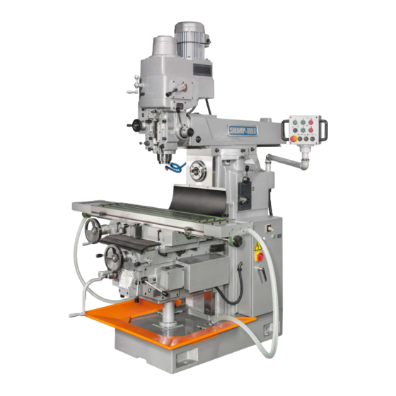
- Page 1 OPERATIONS MANUAL / PARTS LIST...
-
Page 2: Table Of Contents
CONTENTS 1. Outline of machine 1-1 Appearance ......................1 1-2 Features ....................... 1 1-3 Specification ......................2 1-4 External view ....................... 3 2. Installation and preparation 2-1 Transportation of the machine ................4 2-2 Inspection and cleaning ..................5 2-3 Storage and installation ..................5 2-4 Maintenance and inspection .................. -
Page 4: Specification
1-3 Specification Table Working surface length × width 1,300×300mm Travel longitudinal × cross × vertical 950×320×470mm T-slot nominal size × no. × pitch 16mm×3×70mm Longitudinal × cross 60 Hz 13~621mm/min Longitudinal × cross 50 Hz 11~517mm/min Feeds 12 steps Vertical (60 Hz) 7~361mm/min Vertical (50 Hz) 6~263mm/min... -
Page 5: External View
1-4 External view 1-4-1 Table and spindle nose dimensions Chung Sing 3 VERSION: 2... -
Page 6: Installation And Preparation
2. Installation and preparation 2-1 Transportation of the machine When lifting the machine with a crane at the factory site, insert two round bars of about 1-3/8 inch in diameter and use a wire suspension rope of sufficient strength to bear a load of 6,600 lbs. -
Page 7: Inspection And Cleaning
2-2 Inspection and cleaning When the machine is delivered, check for damage or shortages in the number of attachments. Then wipe off dirt and protective coating. 2-3 Storage and installation The surrounding condition of storage is that Temperature range: -25 °c to +75 °C Relative humidity range: 30% to 95 % (non-condensing) Damage from shock and vibration should be avoided Ingress of solid bodies and liquid should be avoided... -
Page 8: Cutting Oil
2-5 Cutting oil There are two general types of cutting oil, i.e., water-soluble cutting oil and water-insoluble cutting oil, and these are further divided into many groups. As selection of the cutting oil depends on each cutting condition, particular trade names or groups cannot be specified here but it is necessary to observe the following: (1) Use of water-insoluble cutting oil. - Page 9 Chung Sing 7 VERSION: 2...
- Page 10 Chung Sing 8 VERSION: 2...
- Page 11 Chung Sing 9 VERSION: 2...
-
Page 12: Name Of Each Part
3. Handling the main operating parts 3-1 Name of each part Fig. 6 Fig. 7 Draw-in blot (1) Main spindle vertical rapid lever Name plate for indicating (2) Spindle quill clamping lever spindle speed. Hand wheel for main spindle (3) Main spindle vertical adjustment vertical feed. -
Page 13: Electric Operation Panel
3-2 Electric operation panel (Fig. 8) Operation ready button Tapping and milling function switch Emergency stop button Horizontal spindle start button Horizontal spindle stop button Vertical spindle start button Vertical spindle stop button Table feed motor start button Cutting oil pump switch (10) Spindle brake switch (11) Table feed motor stop button 3-3 Start, stop and brake for vertical and horizontal spindle... -
Page 14: The Tapping Function Of The Vertical Spindle
3-4 The tapping function of the vertical spindle Steps to operate the tapping function: Turn button (Fig.8 (2)) to the right, and pull the tapping control lever (Fig.9) up for release (Counter-clock-wise), down for tapping (Clock-wise). Fig. 9 3-5 Change of vertical spindle speed The vertical spindle speed should be chosen according to work piece material, cutter diameter and cutter material tables 5 and 6 for you reference. -
Page 15: Change Of Horizontal Spindle Speed
3-6 Change of horizontal spindle speed Move lever (Fig.10 (1)) to position depending upon the spindle speed range required, and move lever (Fig.10 (2)) to the position of the particular speed required. Speed changes must not be made while the main motor is running. To facilitate changing spindle speed, stop main motor by depressing horizontal spindle stop button (Fig.8 (5)). -
Page 16: Vertical Spindle Manual Feed Operation
3-7 Vertical spindle manual feed operation There are two types of manual vertical spindle adjustment, namely, adjustment by hand wheel (Fig.11 (1)) and rapid adjustment by the main vertical spindle adjustment lever (Fig.12 (4)). For general milling, the hand wheel for the vertical spindle adjustment should be used. The handle wheel for the vertical spindle adjustment is providing with a scale collar (Fig.12 (2)). -
Page 17: Operation Of Vertical Spindle Power Down Feed
3-8 Operation of vertical spindle power down feed The vertical automatic feed should be carried out in the following manner. (1) Stop rotation of the main spindle and align the shifter lever (Fig.13 (1)) with the mark + - on the name plate. (2) Select the necessary feed amount (0.048, 0.096, 0.192mm) per revolution with the vertical feed selection knob (Fig.14 (1)) (3) Set the spindle feed direction lever (Fig.13 (2)) either to the up... -
Page 18: Vertical Spindle Quill Clamping
3-10 Vertical spindle quill clamping The spindle quill clamp lever (2) (Fig.7) should be clamped the quill when turned to the right and release the quill when turned to the left. 3-11 Fine reading device for main spindle vertical movement When accuracy is required in vertical feed, the micrometer (Fig.15 (1)) should be clamped to the indicator holder (Fig.15 (2)) with the clamping screw (Fig.15 (3)),and the indicator stopper (Fig.15 (4)) should be fixed at a suitable height by the fixing knob (Fig.15... -
Page 19: Swiveling Of Over Arm On Horizontal Plane
3-13-1 Swiveling of over arm on horizontal plane The over arm can be swiveled by turning the swivel base (Fig.16 (2)) located on the top of the column. Procedure for horizontal swiveling: (1) Loosen the four bolts (Fig.16 (1)) on the left and right side which secure the swivelbase to the column top. -
Page 21: Operation Of Manual Feed
3-15-1 Operation of manual feed Operate longitudinal feed by hand wheel (Fig.18 (1)), cross feed by hand wheel (Fig.18 (3)), and vertical feed by hand lever (Fig.18 (2)). If directional changing lever (Fig.18 (7)) at central front of saddle is in neutral position, longitudinal manual feed can not be operated. -
Page 22: Operation Of Longitudinal Power Feed
3-15-5 Choice of feed speed Feeding speed is dependent on the spindle speed, material of work piece, tips of cutter and diameter of cutter (Table 6). With this machine, 12 steps of cutting feed and rapid feed are carried out from the feed box which is under the side of saddle. Push the button (Fig.8 (8)) to start the table longitudinal feed motor. -
Page 23: Operation Of Dog
3-15-8 Operation of dog The auto-stop longitudinal feed is worked by dogs which are located in the T-slot front of table. The two fixed dogs (Fig.19 (2) (3)) on the outsides are safety stops which prevent over travel. These should not be moved. The two inside dogs (Fig.19 (4) (5)) can be set at any position so that the table stops automatically in set range. -
Page 24: Safety Devices
4. Safety devices 4-1 Thermal relay When electric current exceeding the rating, the thermal relay (Fig.21) is actuated automatically to stop the driving motor. If the thermal relay is actuated, locate and correct the cause and reset the thermal relay by pressing the thermal relay reset push button. 4-2 Fuses Fuses (Fig.21) are installed in the control box to protect electric circuits. -
Page 25: Symbols
5. Symbols The various movements and corresponding symbols used on this machine are indicated in Table 4. Chung Sing 23 VERSION: 2... -
Page 26: Suggested Starting Speed And Feeds
6. Suggested starting speed and feeds 6-1 Carbide cutters Table – 5 Working Piece Cutting Speed High – Speed Steel Cutter Super – Hard Alloy Cutter Brinell Hardness Material M/Min FT/Min M/Min FT/Min Hard 300-400 38-45 30-50 90-150 Special steel Tough 220-300 45-70... -
Page 27: High Speed Steel Cutters
6-2 High speed steel cutters Table – 6 Work Piece Feed Amount Per Tooth MM. Plane Slotting Brinell Face mill saw and Formed blade Materials hardness milling cutter slide mill cutter milling cutter helical milling cutter teeth cutter Hard 300-400 0.075 0.075 0.05...