
Related Manuals for Beko DRYPOINT XFi ecoIntelligent Series


Summary of Contents for Beko DRYPOINT XFi ecoIntelligent Series
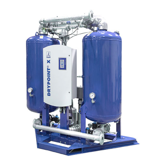
- Page 1 Installation and Operation Manual Heated Blower Purge Regenerated Dryer ® DRYPOINT XFi ecoIntelligent Series XFi models 1000 READ MANUAL FIRST BEFORE INSTALLATION AND OPERATION...
-
Page 3: Table Of Contents
Contents 1. SAFETY AND SYSTEM PRECAUTIONS ..........................5 1.1 Definition of Safety Symbols ..........................5 1.2 Operational Warnings ............................5 2. INSPECTION AND TRANSPORTATION ..........................6 3. TECHNICAL SPECIFICATIONS AND GENERAL FUNCTION ....................6 3.1 Technical Data by Model Size ..........................6 3.2 Correction Factors ............................. - Page 4 5.4.6 Graphs and Data ..........................40 5.4.7 Service and Maintenance ........................ 43 5.4.8 Compressor Synchronization ......................47 5.4.9 Power Requirements ........................47 5.4.10 Network Connection ........................47 5.5 Standard and Optional Features ........................48 5.5.1 ecoIntelligent Control ........................48 5.5.2 Dew point Demand ......................... 49 5.5.3 Compressor Synchronization ......................
-
Page 5: Safety And System Precautions
SAFETY AND SYSTEM PRECAUTIONS Definition of the Safety Symbols Before attempting any Electrical Hazard: Warning: General Warning: Warning: Warning: service, please read Possibility of Under Risk of damage or injury High temperature Non-breathable air the manual electrocution pressure Warning: Warning: Warning: Warning: Warning:... -
Page 6: Inspection And Transportation
Only qualified personnel can use and service electrically powered devices. Before attempting any maintenance: Ensure that no part of the machine is powered and is locked out of the electrical mains by following proper “Lock-out, Tag-out” procedures and requirements. ... - Page 7 DRYPOINT® XFi Model Size 1000 1200 1500 1800 2300 Flow Rate scfm 1000 1200 1500 1800 2300 Inlet / Outlet Connection 150# ANSI Flange Height (A) Width (B) Depth (C) Total Weight per Dryer Lbs. 3,600 4,050 4,700 5,852 6,957 8,763 Max.
-
Page 8: Correction Factors
Correction Factors Sizing must be done by a product specialist, please consult your BEKO Technologies representative for details and sizing assistance. General Function The DRYPOINT® XF heated desiccant dryer series are fitted with two pressure vessels, positioned parallel to one another and filled with adsorption material (⅛”... -
Page 9: Flow Diagram
Flow Diagram Number Name Number Name Inlet Valve Heater Exhaust Valve Purge Valve Blower Depressurization Valve DRYPOINT XFi 1000 manual_revA EN... -
Page 10: Cycle Operation
Cycle Operation After proper pressurization of the dryer, the operator may begin the start-up. During the start-up phase, valves IV-A (1) and IV-B (1) are powered open, while, EV-A (2) and EV-B (2) are powered closed for a period of 40-seconds to help guarantee the complete pressurization of the dryer. -
Page 11: Installation
INSTALLATION Design and Use of the Dryer This dryer has been designed, manufactured and tested to be used only to separate the humidity normally contained in compressed air; any other use is considered to be improper. The manufacturer is not responsible for any problems arising from the improper use of this machine. - Page 12 NOTE: All piping and electrical connections should be inspected prior to installation to ensure they have maintained their integrity during shipping and placement of the dryer. First, make the initial connections as follows: 1. Inlet piping including an isolation valve 2.
-
Page 13: Optimal Istallation Diagram
Optimal Installation Diagram Air Compressor After Cooler CLEARPOINT® Inline Water Separator CLEARPOINT® 5.0 Micron (Grade G) Filtration Receiver Tank CLEARPOINT® 1.0 Micron (Grade F) Filtration DRYPOINT® XF Desiccant Dryer with CLEARPOINT® Pre and Post-filtration (7a & 7b) Dry Air Outlet Condensate Drainage Points for BEKOMAT®... -
Page 14: Dryer Operation
DRYER OPERATION Start-Up 5.1.1 Verification Prior to Start-up Verify that the operating parameters match with the acceptable ranges indicated on the data plate of the dryer (voltage, frequency, air pressure, air temperature, ambient temperature, etc.). This is not the same as the ASME UW plate on the Vessels and may be lower than what is stamped on the ASME UW plate. -
Page 15: Desoccant Fill Procedure
Connect and properly fasten the condensate drain to a collection system or container. The outlet condensate hose cannot be connected to pressurized systems. DO NOT DISPOSE OF CONDENSATE INTO THE ENVIRONMENT The condensate collected in the dryer contains oil particles released into the air stream by the compressor. Dispose of the condensate in a manner compliant with all local, state and Federal rules and regulations. -
Page 16: Start-Up Procedure
5.1.3 Start-up Procedures During the first start-up or start-up after a long period of inactivity or following maintenance, the technician must comply with the instructions below. The start-up must be performed by qualified personnel only. The employee that operates the machine must wear hearing and eye protection before operating the dryer. -
Page 17: General Operation
5.1.4 General Operation Information The dryer may require up to 48-hours of operation to reach normal operating outlet dew point. Therefore, indicators and alarms related to outlet dewpoint, do not need to be recognized during this time. The dryer will not perform as intended without properly sized and installed pre-filtration, condensate drainage and correct purge flow adjustment. -
Page 18: Purge Adjustment
Purge Valve Adjustment The purge flow control valve must be set according to the inlet pressure of the dryer. The valve must be opened to the corresponding number of turns referenced in the table below. Always base the pressure adjustment on the lowest operating pressure of the system The procedure for adjusting the purge flow control valve is as follows: Rendered drawing of purge Turn knob clockwise... -
Page 19: Isolation And Shutdown Procedures
ISOLATION AND SHUT DOWN PROCEDURES Users operating the machine must wear hearing and eye protection. Each employee must select a proper personal protection device (PPD) hearing protector such as earmuffs, ear canal caps or earplugs in order to prevent permanent hearing damage or loss. Isolation 1. -
Page 20: Controller Information And Operation
Controller Information and Operation 5.4.1 Display Overview The interface between the dryer and the operator is the control panel shown below: Outdoor Package: Touch Screen Only Home Button Settings Alarm History Histogram Service & Maintenance The operation of the dryer is controlled and monitored constantly by the advanced system controller. This is a multi- function device: ... -
Page 21: Controller Startup
5.4.2 Controller Startup The main controls power button, outside of the electrical control panel, powers the controller. When pressed, the controller startup sequence begins. This includes a system boot process which takes about 30 seconds. Once the startup sequence is complete, the START window will be displayed. -
Page 22: Home Screen
The START screen is only displayed for 3 seconds, after which, the HOME screen will be displayed and the controller will automatically begin in Startup before the drying sequence commences. 5.4.3 Home Screen HOME After the controller startup, the HOME screen dryer operation is displayed. This screen can be accessed at any time by pressing the HOME button. - Page 23 The controller provides the system information along with an animation of the drying process based on its current operational sequence. Each step is detailed below along with a screen shot of the process. Startup: System Start-up (40 seconds) The controller is evaluating its system parameters to determine the correct step on which to start.
- Page 24 Step 1: Vessel B Close Inlet Valve (2.5 seconds) Vessel B inlet valve closes, stopping inlet air to Vessel B. All inlet air is therefore directed to Vessel A where the desiccant material adsorbs the humidity down to the target dew point. Step 2: Vessel B Open Depressurization Valve (240 seconds) ...
- Page 25 Step 3: Vessel B Open Regeneration Valve (4 minutes) Vessel B regeneration exhaust valve opens. Step 4: Start Vessel B Heating Period - Regeneration (140 minutes) The blower and heater turn on. The blower forces air across the in-line heater and pushes it into the regeneration tower.
- Page 26 Step 5: Start Vessel B Cooling Period - Cooling (86 minutes) The heater turns off while the blower remains on and cools the heater. After the set temperature is reached, the blower turns off and the purge valve opens and additional desiccant bed cooling takes place.
- Page 27 Step 7: Vessel B Energy Savings (20 hours max) If dewpoint demand is installed, the dryer will remain in the drying state on Vessel A. Step 8: Vessel B Parallel Mode (10 minutes) Vessel B inlet valve is opened and inlet air enters Vessel B.
-
Page 28: Controller Settings
NOTE: The cycles are symmetrical for Vessel A and Vessel B: Steps 9 -16 are a repeat of Steps 1-8, but with ‘A’ and ‘B’ side tags switched. After Step 16, the controller will continue back to Step 1. Note that the Step 7 & 15: Energy Saving function is only applicable if it has been enabled in SETTINGS (under the Energy Management option). - Page 29 Global Settings It is important to set the correct Date and Time for the dryer. Dryer alarms are tied to the systems time stamp so, it is important to have this accurate. In case of a power is removed from the controller, the Date and Time are maintained in the memory.
- Page 30 Performance Regeneration includes functional setting for both the Heating Phase and Cooling Phase. Adjustment to these set points are locked and only accessible through an administrative password. Changes can only be made within a specified band of performance. Dew point Demand Dew point demand is a standard feature.
- Page 31 Energy Report Energy Report is where you can track: energy usage of the blower, heater and purge. By entering the energy rate: $/kW we can calculate the total energy consumption. With the ecoIntelligent Control (described in Section 5.5.1) we can look at the energy savings of this function vs dryer running in a fixed time cycle.
-
Page 32: Alarms
5.4.5 Alarms ALARMS The controller has ability to continually monitor specific dryer characteristics along with any ancillary equipment provided it is connected to the controller. If there is a functional issue associated with normal operation, an alarm will be triggered and be displayed as a red background flash on any controller screen: DRYPOINT XFi 1000 manual_revA EN... - Page 33 Alarm Failure Class Regeneration Alarm Regeneration Alarm is an alarm the directly effects the regeneration cycle of the dryer. Pressure Alarm Pressure Alarm is an alarm monitored by a pressure switch or pressure transducer. Temperature Alarm Temperature Alarm is an alarm monitored by a thermocouple. Sensor Failure Alarm Sensor Failure Alarm is a failure in the signal of a sensor to the dryer’s controller after a fixed time delay buffer, i.e.
- Page 34 Regeneration Alarm Alarm ID Description Blower Motor Circuit Breaker Tripped -MAJOR- Motor Starter has tripped due to overcurrent or short circuit. Check overload settings and have qualified electrician troubleshoot wiring for faults. Blower Motor Not Running -MAJOR- Blower motor is not running during regeneration, Check blower operation and have qualified electrician troubleshoot wiring for faults.
- Page 35 Vessel B Repress Failure -MAJOR- Vessel B repressurization failure, check to make sure operation of purge/repress valve is normal and that manual throttling valve is open to ensure fill up. No Air Pressure -MINOR- Check system air pressure. There is no air pressure detected and could be a problem in main air circuit or trouble with compressor operation.
- Page 36 Enclosure Humidity Sensor Failure -MINOR- Enclosure humidity sensor has malfunctioned. Enclosure Temperature Sensor Failure -MINOR- Enclosure temperature sensor has malfunctioned. Vessel A Upper Thermo-well Sensor Failure -MAJOR- Vessel A Upper Thermo-well Sensor has malfunctioned. Vessel B Upper Thermo-well Sensor Failure -MAJOR- Vessel B Upper Thermo-well Sensor has malfunctioned Limit Switch Alarms Alarm ID...
- Page 37 Maintenance Reminders Alarm ID Description Pre-Filter Alarm -MINOR- The recommended maintenance timer interval for the pre-filter change is due soon. Post -Filter Alarm -MINOR- The recommended maintenance timer interval for the pre-filter change is overdue. Service Pre-Filter Soon -MINOR- The recommended maintenance timer interval for the pre-filter change is due soon. Service Pre-Filter Overdue -MINOR- The recommended maintenance timer interval for the pre-filter change is overdue.
- Page 38 Highlighting the alarm then tapping the help button will provide a brief information text. You can also download a log of the alarm history which can be sent to a BEKO Technologies Service Technician for further review. Notices that all past alarms are stored as history in the controller as well as when the alarm was reset.
- Page 39 In ALARM SETTINGS, adjust to the set point of an alarm or delay timer can be adjusted. DRYPOINT XFi 1000 manual_revA EN...
-
Page 40: Graphs And Data
5.4.6 Graphs and Data GRAPHS & DATA The GRAPHS & DATA screen allow access to real time performance data and graphs. This data is captured and logged and available for download. DRYPOINT XFi 1000 manual_revA EN... - Page 41 The Regeneration Phase shows real time temperatures of the regeneration phase. The temperatures are recorded every minute and displayed in a graph. The Performance shows real time pressure of the system. The pressures are recorded every minute and displayed in a graph. DRYPOINT XFi 1000 manual_revA EN...
- Page 42 The Enclosure / Ambient Info shows real time temperature, humidity from the controls enclosure and ambient environment. The temperature and humidity are recorded every minute and displayed in a graph. DRYPOINT XFi 1000 manual_revA EN...
-
Page 43: Service And Maintenance
5.4.7 Service and Maintenance SERVICE & MAINTINANCE Service and Maintenance allows the access to information such as: Maintenance and spare part order numbers Setting maintenance interval reminders Electronic copy of the product manual General system information DRYPOINT XFi 1000 manual_revA EN... - Page 44 Operating Hours show time related information of the dryer, including: Comparison of the current time cycle for the major steps to the previous time cycle: heating, cooling, and drying. Total operating hours of the dryer. DRYPOINT XFi 1000 manual_revA EN...
- Page 45 The Information shows: Controller software version PLC seral number Manufacturing date In addition to the contact information of BEKO Technologies, Corp. DRYPOINT XFi 1000 manual_revA EN...
- Page 46 Spare Parts provides an abbreviated spare parts list for the dryer with description and part number that can be used to order from customer service. The Maintenance Timers button allows the user to observe (in hours): • Initial maintenance alarm for the listed characters •...
-
Page 47: Compressor Synchronization
The is a locked function and should only be access by qualified personnel to carry out service on the dryer. Observance of all safety precautions and procedures must be taken. Manipulation of the heater, blower and switches can be made for service and testing. - Page 48 For additional information on how to use the controller network capability, contact your local distributor. For technical support contact BEKO Technologies, Corp. Only qualified personnel may carry out the service for the network connection of the dryer. Before any service make sure that no parts of the machine are powered.
-
Page 49: Standard And Optional Features
Standard and Optional Features 5.5.1 ecoIntelligent Control (Standard) The ecoIntelligent Control provides the user with: performance selection, system monitoring, optimized energy savings and detailed reporting. Performance Selection Performance selection of the dryer is done mainly through the Dew point Demand (described in section 5.5.2) integrated into the ecoIntelligent Control. -
Page 50: Dew Point Demand
Dryer outlet dew point is continually read by the BEKO METPOINT SD 21 dew point sensor and transmitted to the BEKOTOUCH 2 controller. This data is displayed in real time on the HOME screen and also displayed as a trend line in the GRAPHS &... -
Page 51: Valve Position Indicators
5.5.7 Valve Position Indicators (Standard) Valve position indicators are mounted on the inlet and regeneration exhaust valves of the dryer. These provide a visual indication of the valve state (open or closed) and an electrical signal into the dryer’s BEKOTOUCH 2 controller. If the valve is detected in the improper state based on the sequence step, the dryer will alarm. -
Page 52: Maintenance And Service Information
MAINTENANCE AND SERVICE Maintenance and Service Information 6.1.1 Routine Maintenance The service must be carried out only by a qualified technician. Before any service is carried out, always verify that: The power has been disconnected following proper Lock-out, Tag-out procedures ... -
Page 53: Maintenance And Service Intervals
6.1.2 Maintenance and Service Intervals Preventative maintenance of the pre and post-filter element, and desiccant material is required. The controller monitors the dryers operating hours and will activate the maintenance alarms when certain values are reached. Initial Alarm Reminder Pre-filter Every 8,000 hours Every 800 hours Post-filter... -
Page 54: Required Maintenance Parts
If you need to replace any other parts, please contact your local distributor or BEKO Technologies, Corp. Technical Service Department at +1 (800) 235-6797 for assistance. -
Page 55: Spare Parts
6.2.2 Spare Parts DESCRIPTION Order No. 1000 Wafer Check Valve 2-1/2" 4029374 2 3” 4029375 2 Pressure Relief Safety Valve ¾” Pressure Relief Safety Valve 4026668 2 Purge Flow Control ¾” Purge Flow Control Valve 4032820 ¾“ Purge On/Off Valve 4034368 Muffler Assembly 1/2”... -
Page 56: Troubleshooting Guide
DESCRIPTION Order No. 1500 Additional Electrical Components Contactors 4040827 Motor Starter 4034811 Relay 4034796 2 Power Supply 4034837 Thermocouple, In Vessel Bed On Request 2 Thermocouple, Inlet / Outlet On Request Thermocouple, Regen Exhaust On Request NOTE: When inquiring about any other part always indicate the data listed on the identification plate. - Page 57 Purge Exhaust Valve See purge Exhaust Valve troubleshooting ❖ Repressurization Purge line Purge setting or clog, full open purge valve to clean out and then set according to table xx Purge Valve See Purge valve troubleshooting ...
- Page 58 check pilot valve, pilot air supply, pilot air filter, flow Electrical control valve on actuator Restriction Check power to solenoid valves Backpressure – silencers or mufflers are clogged, install new muffler elements ❖ Inlet Valve ...
-
Page 59: Dismantling Of The Dryer
DISMANTLING OF THE DRYER If the dryer is to be dismantled and disposed of then it must be split into groups of materials of construction. Part Material Desiccant material Activated alumina, Oil contaminated Frame and supports Carbon steel, Powder coated Piping Galvanized steel, Galvanized malleable iron, Brass, Aluminum Vessels and screens Carbon steel, Stainless steel... -
Page 60: General Description Of Parts
GENERAL DESCRIPTION OF PARTS Desiccant – An adsorbent used for drying air or gases. The proper quantity, size and type are necessary. Inlet Valve – Double acting air operated switching valves used to direct air flow through the Vessels. ... - Page 61 For technical product support please call +1 (800) 235-6797 and select Option 2 DRYPOINT XFi 1000 manual_revA EN...