Advertisement
Quick Links
Instructions for:
FILTER/REGULATOR -
REGULATOR
Thank you for purchasing a Sealey product. Manufactured to a high standard this product will, if used according
to these instructions and properly maintained, give you years of trouble free performance.
IMPORTANT: PLEASE READ THESE INSTRUCTIONS CAREFULLY. NOTE THE SAFE OPERATIONAL
REQUIREMENTS, WARNINGS AND CAUTIONS. USE THE PRODUCT CORRECTLY AND WITH CARE FOR THE
PURPOSE FOR WHICH IT IS INTENDED. FAILURE TO DO SO MAY CAUSE DAMAGE AND/OR PERSONAL
INJURY AND WILL INVALIDATE THE WARRANTY. PLEASE KEEP INSTRUCTIONS SAFE FOR FUTURE USE.
1.
SAFETY INSTRUCTIONS
F
WARNING! Ensure that Health & Safety, local authority, and general workshop practice
regulations are adhered to when using this equipment.
F
WARNING! Disconnect the equipment from the air supply before changing accessories,
servicing or performing any maintenance.
! Keep the equipment clean and maintain it in good condition (use an authorised service agent).
! Replace or repair damaged parts. Use genuine parts only. Unauthorised parts may be
dangerous and will invalidate the warranty.
F
WARNING! Ensure that the correct air pressure is maintained and not exceeded.
! Keep air hoses away from heat, oil and sharp edges. Check air hoses for wear before each
use and ensure that all connections are secure.
% DO NOT direct air from the air hose at yourself, others or animals.
! Drain the compressor air tank daily. Water in the air line will damage equipment.
! When work is complete ensure that the air supply is turned off.
2.
INTRODUCTION & SPECIFICATIONS
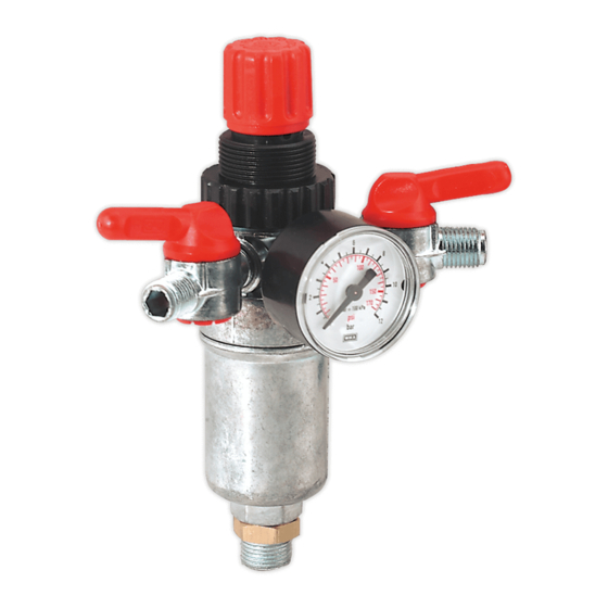
Heavy-duty aluminium alloy valve assemblies with large gauges dual marked in psi and bar. Pressure control knob can be locked
in position to prevent accidental alteration. SA4FR/38 features integral filter. Air outlets are fitted with shut-off valves.
SA4FR/38
Max. inlet/output pressure - psi/bar . . . . . . . . . . 174/12. . . . . . . . . . . . . . . 174/12
Working pressure range - psi/bar. . . . . . . . . 30-120/2-8 . . . . . . . . . . . 30-120/2-8
Max. flow rate - cfm . . . . . . . . . . . . . . . . . . . . . . . . 76 . . . . . . . . . . . . . . . . . . 76
Inlet . . . . . . . . . . . . . . . . . . . . . . . . . . . . . . 3/8”BSP(M) . . . . . . . . . . . 1/4”BSP(F)
Outlet. . . . . . . . . . . . . . . . . . . . . . . . . . 2 x 1/4”BSP(M) . . . . . . . . 1 x 1/4”BSP(M)
3.
CONTENT & INSTALLATION
3.1.
Confirm that all items are present and undamaged. If any parts are missing or damaged please contact the supplier.
SA4FR/38 - Combined filter/regulator with gauge.
SA5/RG/14 - Regulator and gauge.
3.2.
Fig.1 shows a typical air line installation. The filter is located
upstream of the regulator - unless combined - and the
lubricator downstream.
3.2.1.
When installing the filter/regulator or regulator ensure that:
a) Gauge is visible
b) Regulator control is accessible
c) Flow direction arrow (SA5/RG/14) matches system air flow.
SA4FR/38 The inlet on is at the base of the filter body and the
outlets are either side of the gauge.
SA5/RG/14 The inlet and outlet are on the sides of the body
with the gauge between them.
Note: To ensure air-tight joints use PTFE tape.
SA4FR/38
- SA5/RG/14
SA4FR/38
SA5/RG/14
SA5/RG/14
fig. 1
SA4FR/38 & SA5/RG/14 - 1 - 041102
Instructions for:
FILTER/REGULATOR -
REGULATOR
Thank you for purchasing a Sealey product. Manufactured to a high standard this product will, if used according
to these instructions and properly maintained, give you years of trouble free performance.
IMPORTANT: PLEASE READ THESE INSTRUCTIONS CAREFULLY. NOTE THE SAFE OPERATIONAL
REQUIREMENTS, WARNINGS AND CAUTIONS. USE THE PRODUCT CORRECTLY AND WITH CARE FOR THE
PURPOSE FOR WHICH IT IS INTENDED. FAILURE TO DO SO MAY CAUSE DAMAGE AND/OR PERSONAL
INJURY AND WILL INVALIDATE THE WARRANTY. PLEASE KEEP INSTRUCTIONS SAFE FOR FUTURE USE.
1.
SAFETY INSTRUCTIONS
F
WARNING! Ensure that Health & Safety, local authority, and general workshop practice
regulations are adhered to when using this equipment.
F
WARNING! Disconnect the equipment from the air supply before changing accessories,
servicing or performing any maintenance.
! Keep the equipment clean and maintain it in good condition (use an authorised service agent).
! Replace or repair damaged parts. Use genuine parts only. Unauthorised parts may be
dangerous and will invalidate the warranty.
F
WARNING! Ensure that the correct air pressure is maintained and not exceeded.
! Keep air hoses away from heat, oil and sharp edges. Check air hoses for wear before each
use and ensure that all connections are secure.
% DO NOT direct air from the air hose at yourself, others or animals.
! Drain the compressor air tank daily. Water in the air line will damage equipment.
! When work is complete ensure that the air supply is turned off.
2.
INTRODUCTION & SPECIFICATIONS
Heavy-duty aluminium alloy valve assemblies with gauges dual marked in psi and bar. Pressure control knob can be locked in
position to prevent accidental alteration. SA4FR/38 features integral filter. Air outlets are fitted with shut-off valves.
SA4FR/38
Max. inlet/output pressure - psi/bar . . . . . . . . . . 174/12. . . . . . . . . . . . . . . 174/12
Working pressure range - psi/bar. . . . . . . . . 30-120/2-8 . . . . . . . . . . . 30-120/2-8
Max. flow rate - cfm . . . . . . . . . . . . . . . . . . . . . . . . 76 . . . . . . . . . . . . . . . . . . 76
Inlet . . . . . . . . . . . . . . . . . . . . . . . . . . . . . . 3/8”BSP(M) . . . . . . . . . . . 1/4”BSP(F)
Outlet. . . . . . . . . . . . . . . . . . . . . . . . . . 2 x 1/4”BSP(M) . . . . . . . . 1 x 1/4”BSP(M)
3.
CONTENT & INSTALLATION
3.1.
Confirm that all items are present and undamaged. If any parts are missing or damaged please contact the supplier.
SA4FR/38 - Combined filter/regulator with gauge.
SA5/RG/14 - Regulator and gauge.
3.2.
Fig.1 shows a typical air line installation. The filter is located
upstream of the regulator - unless combined - and the
lubricator downstream.
3.2.1.
When installing the filter/regulator or regulator ensure that:
a) Gauge is visible
b) Regulator control is accessible
c) Flow direction arrow (SA5/RG/14) matches system air flow.
SA4FR/38 The inlet on is at the base of the filter body and the
outlets are either side of the gauge.
SA5/RG/14 The inlet and outlet are on the sides of the body
with the gauge between them.
Note: To ensure air-tight joints use PTFE tape.
SA4FR/38
- SA5/RG/14
SA4FR/38
SA5/RG/14
SA5/RG/14
fig. 1
SA4FR/38 & SA5/RG/14 - 1 - 041102
Advertisement

Related Manuals for Sealey SA4FR/38


Summary of Contents for Sealey SA4FR/38
- Page 1 REGULATOR REGULATOR Thank you for purchasing a Sealey product. Manufactured to a high standard this product will, if used according Thank you for purchasing a Sealey product. Manufactured to a high standard this product will, if used according to these instructions and properly maintained, give you years of trouble free performance.
- Page 2 When setting output pressure always adjust up from a lower pressure. 4.2. Filter (SA4FR/38) - The filter should be cleaned regularly. Unscrew the filter housing from the regulator body to access the filter. 4.2.