Advertisement
Quick Links
Thank you for purchasing a Sealey product. Manufactured to a high standard this product will, if used according to these instructions and
properly maintained, give you years of trouble free performance.
IMPORTANT: PLEASE READ THESE INSTRUCTIONS CAREFULLY. NOTE THE SAFE OPERATIONAL REQUIREMENTS, WARNINGS & CAUTIONS.
USE THE PRODUCT CORRECTLY AND WITH CARE FOR THE PURPOSE FOR WHICH IT IS INTENDED. FAILURE TO DO SO MAY CAUSE
DAMAGE AND/OR PERSONAL INJURY AND WILL INVALIDATE THE WARRANTY. PLEASE KEEP INSTRUCTIONS SAFE FOR FUTURE USE.
1. SAFETY INSTRUCTIONS
ü Ensure the pipe bender is in sound condition and good working order.
Take action for immediate repair or replacement of damaged parts. Use
recommended parts only. The use of improper parts may be dangerous
and will invalidate the warranty.
ü Keep bender and associated parts clean for best and safest performance.
ü Locate the pipe bender in a suitable, well lit work area.
ü Keep work area clean and tidy and free from unrelated materials.
ü Use on level and solid ground, preferably concrete.
ü Ensure all non-essential persons keep a safe distance whilst the pipe
bender is in use.
ü Check that bending die is correctly seated on ram and that roller shafts are
fully engaged in the frame before operating hydraulic unit.
ü Use a qualified person to lubricate and maintain the hydraulic unit.
ü Confirm that the recommended hydraulic oil is used during maintenance.
ü Wear appropriate safety clothing including cloves and eye protection.
ü Keep hands away from die and rollers when bending pipe.
▲ Caution! Cut pipe edges may be sharp, take care when handling any cut
steelwork.
û DO NOT operate the pipe bender if damaged.
û DO NOT allow untrained persons to operate the pipe bender.
û DO NOT exceed the rated capacity of the hydraulic unit (see below).
û DO NOT use the pipe bender for purposes other than that for which it
is intended.
û DO NOT top up system with brake fluid. Use hydraulic oil only.
û DO NOT alter the pressure control valve.
ü Store pipe bender in a dry, childproof area, with the hydraulic
ram retracted.
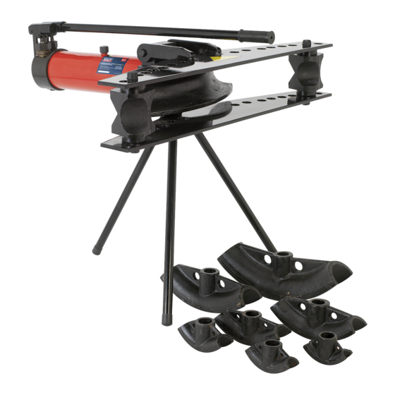
2. INTRODUCTION & SPECIFICATION
Tripod mounted pipe benders suitable for bending pipes up to 180° (3 x 60°
bends). Compact hydraulics with integral 9 or 15 ton ram. Suitable for bending
DIN classified medium and heavy pipe. Two-speed hydraulic pump gives fast
positioning of pipe in dies and the power to bend up to 50mm pipe (PBS90), or
75mm pipe (PBS91). The units are supplied with six/eight interchangeable pipe
dies and are supplied in a heavy wooden crate for easy transportation.
MODEL: .............................................. PBS90........................................ PBS91
Maximum Load .........................................9ton...........................................15ton
Maximum Pipe Ø ...................................50mm..........................................75mm
Height ..................................................700mm........................................700mm
Weight .....................................................53kg.......................................... 117kg
Die Sizes .................13mm(1/2"), 19mm(3/4") ............ 13mm(1/2"), 19mm(3/4")
................................ 25mm(1"), 31mm(1-1/4") ............ 25mm(1"), 31mm(1-1/4")
.................................37mm(1-1/2"), 50mm(2") ............ 37mm(1-1/2"), 50mm(2")
..................................................................................... 64mm(2-1/2"), 75mm(3")
INSTRUCTIONS FOR:
INDUSTRIAL PIPE BENDERS 9 & 15 TON
MODEL No's:
3. ASSEMBLY
WARNING! Ensure that you have read and understood Section 1
Safety Instructions before operating the pipe bender.
WARNING! When the pipe bender is packed in its box it is
extremely heavy and will require at least 2 people to move it.
The pump unit itself is also very heavy and should be handled
with care.
3.1
Remove the pump unit from the box and place it upside down on a
smooth flat clean surface.
3.2
Identify the four 12mm socket cap mounting bolts and slide a spring
washer and then a plain washer onto each bolt. Referring to fig.1 align
the four mounting holes in the lower plate (A) with the threaded holes
in the block at the front of the pump unit. Insert the four 12mm socket
cap bolts and screw down finger tight. Take the 10mm hex key
provided and fully tighten the four bolts.
3.3
Adjacent to the mounting bolts are three tubular sockets for the tripod
legs. Insert a tripod leg into each socket. See D in fig.1. Screw an 8mm
socket cap bolt through the side of each socket to clamp the legs in
place as shown at E in fig.1. Tighten each bolt using the 6mm hex key.
3.4
Turn the assembly the right way up so that it is standing on its tripod
legs. Care should be taken when doing this, get another person to help
you as the unit is heavy.
3.5
Locate the bending rollers (see Z above) into suitable holes in the lower
plate (A) so that they are displaced equally either side of the pump unit.
3.6
Identify the pivot pin (C) for the upper plate (B) and have it ready for
insertion. (see fig.2.)
3.7
Lower the upper plate (B) onto the pipe bender so that the upward
facing shafts of the bending rollers locate into the plate and the pivot
arms are lying either side of the front of the pump block. Referring to
fig.2 align holes 'X' in the pivot arms with the hole 'Y' in the pump block
and fully insert the pivot pin (C).
4. OPERATION
When using hydraulic type pipe benders, the bent pipe or
tube is prone to deformation on both the inside and outside
curvature. The pipe or tube can be deformed into an oval
shape or creased depending on the wall thickness of the
material. This is not a fault and largely unavoidable.
Consider packing the pipe or tube with dried sand or similar
medium before bending as this may help to alleviate
fig.1
deformation of the pipe or tube. Pack the sand tight and cap
both ends.
PBS90.V2 PBS91.V4
PBS90.V2, PBS91.V4
fig.2
Issue No:2 07/01/16
Advertisement

Related Manuals for Sealey PBS90.V2


Summary of Contents for Sealey PBS90.V2
- Page 1 PBS90.V2 PBS91.V4 MODEL No's: Thank you for purchasing a Sealey product. Manufactured to a high standard this product will, if used according to these instructions and properly maintained, give you years of trouble free performance. IMPORTANT: PLEASE READ THESE INSTRUCTIONS CAREFULLY. NOTE THE SAFE OPERATIONAL REQUIREMENTS, WARNINGS & CAUTIONS.
- Page 2 6. DECLARATION OF CONFORMITY Parts support is available for this product. To obtain a parts listing and/or diagram, please log on to www.sealey.co.uk, email sales@sealey.co.uk or phone 01284 757500. NOTE: It is our policy to continually improve products and as such we reserve the right to alter data, specifications and component parts without prior notice.