Canon iP2700 Simplified Service Manual
Hide thumbs
Also See for iP2700:
- Getting started (32 pages) ,
- Specification sheet (1 page) ,
- Manual (4 pages)
Advertisement
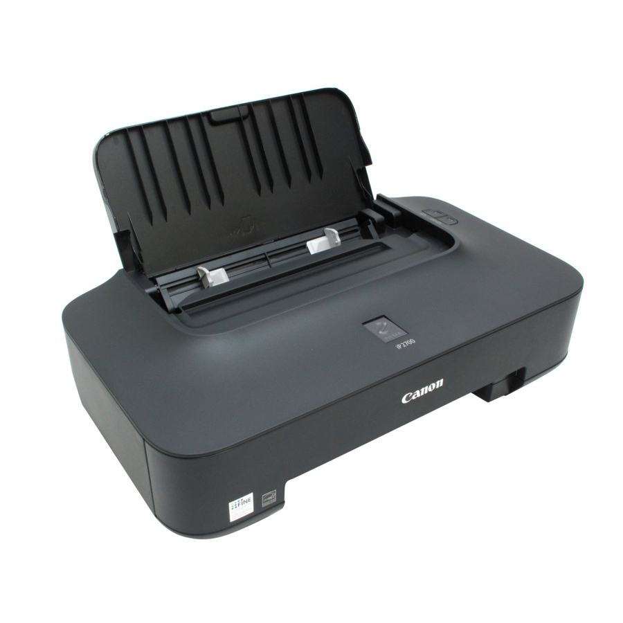
iP2700 / iP2770 / iP2780
SIMPLIFIED SERVICE MANUAL
1. LIST OF ERROR DISPLAY / TROUBLESHOOTING
1-1. Operator Call Errors (Alarm Lamp Lit In Orange)
1-2. Service Call Errors (by Cyclic Blinking of Alarm and Power Lamps)
2. ADJUSTMENT / SETTINGS
2-1. Service Mode
2-2. User Mode
2-3. Special Notes on Servicing
2-4. Grease Application
3. EXTERNAL VIEW / PARTS LIST
3-1. External Housing, Power Supply, Logic Board
3-2. Print Unit (1/2)
3-3. Print Unit (2/2)
3-4. Parts List
QY8-13CR-000
Rev. 00
Jan. 2010
Canon Inc.
(1/23)
Advertisement
Table of Contents

Related Manuals for Canon iP2700


Summary of Contents for Canon iP2700
- Page 1 / iP2770 / iP2780 SIMPLIFIED SERVICE MANUAL 1. LIST OF ERROR DISPLAY / TROUBLESHOOTING 1-1. Operator Call Errors (Alarm Lamp Lit In Orange) 1-2. Service Call Errors (by Cyclic Blinking of Alarm and Power Lamps) 2. ADJUSTMENT / SETTINGS 2-1.
-
Page 2: List Of Error Display / Troubleshooting
1. LIST OF ERROR DISPLAY / TROUBLESHOOTING Errors and warnings are displayed by the following ways: - Operator call errors are indicated by the Alarm lamp lit in orange. - Messages during printing from a computer are displayed on the printer driver Status Monitor. - Error codes are printed in the "operator call/service call error record"... - Page 3 Error Error (Blinking in Status Monitor message Solution code orange) Non-supported [1485] 5 times The following ink cartridge cannot be A non-supported ink cartridge is ink cartridge recognized. installed. Install the supported ink installed. Color cartridge. If the error is not Black cleared, the ink cartridge may be defective.
- Page 4 5 seconds. in the printer EEPROM that the Canon recommends to use new function to detect the remaining genuine Canon cartridges in order to ink amount was disabled. obtain optimum qualities. Please be advised that Canon shall not be liable for any malfunction or trouble caused by continuation of printing under the ink out condition.
- Page 5 Error Error (Blinking in Status Monitor message Solution code orange) No ink (no raw [1688] 16 times The following ink has run out. Replace the empty ink ink). Color cartridge(s). Printing with an Black empty ink cartridge can damage the printer. Replace the ink cartridge and close However, to continue printing the cover.
- Page 6 1-2. Service Call Errors (by Cyclic Blinking of Alarm and Power Lamps) Cycles of blinking of Error Solution Error Alarm and Conditions code (Check points and replacement items) Power LEDs Carriage error [5100] 2 times An error occurred in the 1) Foreign material or paper debris that carriage encoder signal.
-
Page 7: Adjustment / Settings
2. ADJUSTMENT / SETTINGS 2-1. Service Mode < Service mode operation procedures > Use the Service Tool on the connected computer. Start the printer in the service mode. With the printer power turned off, while pressing the Resume/Cancel button, press and hold the ON button. - Page 8 Name Function Remarks Test Print Service test print Service test print: - Model name - ROM version - Ink absorber counter value (ink amount in the ink absorber) - USB serial number - Destination - EEPROM information - Barcode (model name + destination), etc. EEPROM EEPROM information The dialog box opens to select the paper source.
- Page 9 Name Function Remarks (12) Platen Platen ink absorber Not used. counter resetting (13) EEPROM Clear EEPROM initialization The following items are NOT initialized, and the shipment arrival flag is not on: - Destination settings - Ink absorber counter value - Record of disabling the function to detect the remaining ink amount - Printer serial number - Ink cartridge region code...
-
Page 10: User Mode
2-2. User Mode Function Procedures Remarks Nozzle check pattern Perform from the printer driver Set a sheet of plain paper (A4 or Letter) in printing Maintenance tab. the rear tray. Print head cleaning Perform from the printer driver Unclogging of the print head nozzles, and Maintenance tab. -
Page 11: Special Notes On Servicing
2-3. Special Notes on Servicing (1) Carriage rail and main chassis adjustment < Carriage rail > Perform the following adjustments when attaching the carriage rail: 1) Before loosening the screws, mark their positions on the rail. In attaching the carriage rail, make sure that the screws fit to the marks made in step 1) respectively, then fasten the screws. - Page 12 If extra portion is long, fix the cables with tape, etc. (3) Ink absorber replacement The following two replacement methods are available for the iP2700 / iP2770 / iP2780. Difficultie Ink absorber volume to be Print yield after Time required...
- Page 13 < How to perform the partial replacement > i. Remove the external housing, while referring to the photo below. Remove 4 screws, then remove a set of the ASF cover, front cover, and middle frame. ii. Pull out the ink absorber (QC2-8308). Absorber for Partial Replacement iii.
- Page 14 2) Whole replacement Remove the external housing and printer unit, then replace all the ink absorbers. The ink absorber counter value must be reset to 0%. (Time required: Approx. 20 min. including the operation check after replacement) Absorbers for Whole Replacement <...
- Page 15 (5) PCB connector layout and flexible cable wiring In previous models, the ASF sensor, PE sensor, and LF encoder sensor were directly soldered to the logic board. However, in the iP2700 / iP2770 / iP2780, connectors are adopted for their connection for higher serviceability. LF ENC ASF / PE Sensor <...
- Page 16 (6) Sensors Carriage Encoder Sensor ASF / PE Sensor Cover Open Sensor LF Encoder Sensor Sensor Function Possible problem ASF / PE sensor Detects paper feeding and ejection from the - No paper in the rear tray rear tray. - Paper jam in the rear tray Cover open sensor Detects opening and closing of the front - The carriage does not move to the cover.
-
Page 17: Grease Application
2-4. Grease Application Location & Grease Amount FLO I L K G -107A Printer Unit ④ Grease to be applied to the area 1.2 mm ④ ② from the bottom to 4.2 mm. Grease can extend to the area 0.7 mm from the bottom to 1.2 mm, and from 4.2 mm to 4.7 mm. - Page 18 Bottom Frame M O LY K O TE P G -641 9 to 18 mg x 4 locations 9 to 18 mg x 4 locations (1 location = one side of the boss) FLO I L K G -107A Trigger Arm Platen M O LY K O T E P G -641 Carriage sliding portion:...
-
Page 19: External View / Parts List
3. EXTERNAL VIEW / PARTS LIST 3-1. External Housing, Power Supply, Logic Board (19/23) -
Page 20: Print Unit
3-2. Print Unit (1/2) (20/23) - Page 21 3-3. Print Unit (2/2) (21/23)
-
Page 22: Parts List
3-4. Parts List Part Number Rank Description Remarks QC3-2776-000 COVER, ASF QM3-6638-000 ACCESS COVER UNIT iP2700 QM3-7343-000 ACCESS COVER UNIT iP2770 QM3-7344-000 ACCESS COVER UNIT iP2780 QM3-7346-000 ACCESS COVER UNIT iP2772 QM3-7347-000 ACCESS COVER UNIT iP2702 QC3-0010-000 EMBLEM For Japan... - Page 23 Part Number Rank Description Remarks XB1-2300-405 SCREW, MACH.BH, M3x4 XA9-1493-000 SCREW, TP M3x8 XA9-1752-000 SCREW, TAP, WASHER HEAD, M3x12 XA9-1818 XB1-2260-305 SCREW, MACH. TRUSS HEAD, M2.6x3 XB1-2300-605 SCREW, MACHINE, M3x6 XB6-7300-605 SCREW, MACHINE, TP, M3x6 XB1-2200-505 SCREW, MACH, TRUSS HEAD, M2x5 XB4-7300-805 SCREW, TP, BH3x8 (23/23)