
Related Manuals for LG MASTER-K Series


Summary of Contents for LG MASTER-K Series
- Page 1 User’ s Manual LG Programmable Logic Controller GLOFA G3F-HSCA G4F-HSCA MASTER-K G6F-HSCA LG Industrial Systems...
- Page 2 SAFETY PRECAUTIONS Be sure to read carefully the safety precautions given in data sheet and user’s manual before operating the module and follow them. The precautions explained here only apply to the high-speed counting module. For safety precautions on the PLC system, see the GLOFA PLC GM3/4/6 and MASTER-K200S/300S/1000S CPU User’s Manuals.
- Page 3 Wiring Precautions CAUTION ▶ When grounding a FG terminal, be sure to provide class 3 grounding which is dedicated to the PLC. ▶ Before the PLC wiring, be sure to check the rated voltage and terminal arrangement for the module and observe them correctly. If a different power, not of the rated voltage, is applied or wrong wiring is provided, it can cause a fire or disorder of the nodule.
-
Page 4: Table Of Contents
◎ CONTENTS ◎ Chapter 1. INTRODUCTION Chapter 2. SPECIFICATIONS 2.1 General Specifications …………………………………………………………………… 2-1 2.2 Performance Specifications ……………………………………………………………… 2-2 2.2.1 Basic performance specification 2- 2 … … … … … … … … … … … … … … … … … … … … … … … 2.2.2 Input specification …... - Page 5 Chapter 4. FUNCTION BLOCK 4.1 Insertion of the Function Block for Hgh Speed Counter on the GMWIN ………… 4-1 4.2 Local Function Block ……………………………………………………………………… 4-2 4.2.1 The specfication of the preset value(HSC_PRE) 4- 2 … … … … … … … … … … … … … … … … … 4.2.2 The specfication of the comparison value ( HSC_CMP) …...
- Page 6 6.1 Operating block diagram ………………………………………………………………… 6-1 6.2 Input / Output signal configuration …………………………………………………… 6-3 6.2.1 G3F-HSCA … … … … … … … … … … … … … … … … … … … … … … … … … … … … … … … 6.2.2 G4F-HSCA / G6F-HSCA …...
- Page 7 Chapter 9. DIMENSIONS Dimensions…………………………………………………………………………………… 9-1...
- Page 8 Chapter 1. INTRODUCTION Chapter 1. INTRODUCTION This manual describes the specifications, handling instructions, and programming information for the G3F– HSCA, the G4F– HSCA and the G6F-HSCA. It is the high speed counting module used with CPU of the GLOFA PLC GM1/2/3/4/6 series and the MASTER-K200S/300S/1000S series.
-
Page 9: Chapter 2. Specifications
Chapter 2. SPECIFICATION S Chapter 2. SPECIFICATIONS 2.1 General Specifications Table 2.1 shows general specifications of the GLOFA GM series and MASTER-K series. Item Specifications Standards Operating ambient 0 ~ 55℃(32 ~ 131℉) temperature Storage ambient -25 ~ 75℃(-13~167℉) temperature... -
Page 10: Performance Specifications
Chapter 2. SPECIFICATION S 2.2 Performance Specifications The following show various specifications of the High-speed counting module including basic performance specifications, input specifications, limit switch input specifications and transistor output specifications. 2.2.1 Basic Performance Specification Specifications I t e m G 3 F - H S C A G 4 F - H S C A G 6 F - H S C A... - Page 11 Chapter 2. SPECIFICATION S 2.2.2 Input Specifications I t e m Specifications 5 VD C (7 mA) Rated input voltage / current 12 VD C (7 mA) 24 VD C (13 mA) 5 VD C 4.5 V or more ' On ' guarantee voltage 12 VD C 11 V or more 24 VD C...
-
Page 12: Names Of Parts And Functions
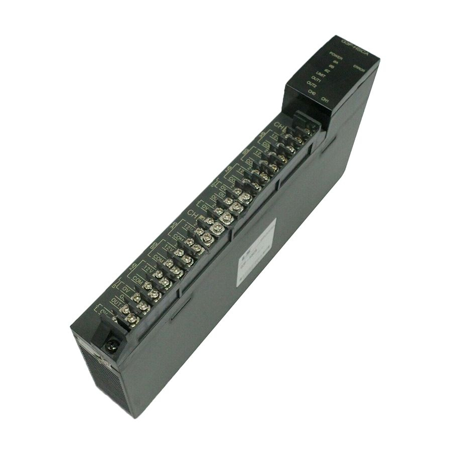
Chapter 2. SPECIFICATION S 2.3 Names of Parts and Functions 2.3.1 Names of Parts and Functions The names of parts and functions of the high speed counter module are shown as below Indicators Input/ output terminal block Dip switch Setting part 2 - 4... - Page 13 Chapter 2. SPECIFICATION S Indicators Dip switch setting part Input/ output terminal block G6F- READY Φ A PRESET Φ B OUT1 Indicators Φ Z OUT2 K3F-HSCA G 6 F - H S C A Φ A Φ B Input/ output Connector Φ...
-
Page 14: Function Of Led Indicators
Chapter 2. SPECIFICATION S 2.3.2 Function of LED Indicators Description G3F-HSCA Power LED E R R OR POWER Turns On when the power is applied. ① Error LED Turns on for 0.5 sec when the power is applied and then turns off if the system is normally running. LIMIT Flickers with 0.1 sec, 0.2 sec or 0.3 sec cycle ②... -
Page 15: Dip Switch Setting Part
Chapter 2. SPECIFICATION S 2.3.3 DIP Switch Setting Part The DIP Switch settings are used for phase-2/ phase-1 operation mode specification, Increment / Decrement count method specification at 1-phase operation, and multiplication specification at 2-phase operation. G3F-HSCA G4F-HSCA/G6F-HSCA Channel 0 Channel 1 Switch Functions... - Page 16 Chapter 2. SPECIFICATION S 2 - 8...
-
Page 17: Input / Output Terminal Block
Chapter 2. SPECIFICATION S 2.3.4 Input / Output Terminal Block 1) G3F-HSCA/G4F-HSCA ● Phase A pulse Input Terminal One of 24V, 12V and 5V is selected ● Phase B pulse Input Terminal One of 24V, 12V and 5V is selected ●... - Page 18 Chapter 2. SPECIFICATION S 2 ) G 6 F - H S C A ● Phase A pulse Input Terminal One of 24V, 12V and 5V is selected Φ A ● Phase B pulse Input Terminal One of 24V, 12V and 5V is selected Φ...
-
Page 19: Interface With External Devices
Chapter 2. SPECIFICATION S 2.4 Interface with External Devices Table 2.1 and Table 2.2 shows the list for interface with external devices. 1) G3F-HSCA/G4F-HSCA Termina I n p u t l No. Operatio Internal Current Signal Name guarantied Voltage 14~26.4 V 24 V, Phase A pulse input 2.5 V... - Page 20 Chapter 2. SPECIFICATION S External power supply [Table 2.1] External interface list ( G3F-HSCA / G4F-HSCA ) 2 ) G 6 F - H S C A I n p u t Terminal Operatio Internal Current Signal Name guarantied p i n N o . Voltage 14~26.4 V 24 V, Phase...
- Page 21 Chapter 2. SPECIFICATION S External power supply output 24 V Input voltage 10.2 ~ 30 V External power supply [Table 2.2] External interface list ( G6F-HSCA ) 2 - 13...
-
Page 22: Output Mode Of Encoder
Chapter 2. SPECIFICATION S 2.5 Output Mode of Encoder Open collector output High speed counter 24V phase A, B or Z pulse input V o l t a g e o u t p u t High speed counter 24 V phase A, B or Z pulse input 2 - 14... -
Page 23: Function Descriptions
Chapter 2. SPECIFICATION S 2.6 Function Descriptions The High-speed counting module can count high-speed pulse which cannot be proceed with the CPU counting instructions (CTU,CTUD, etc.). Up to 24 bits binary (16,777,215) can be counted. Pulse input mode is classified into 1-Phase (Phase A) pulse input and 2-Phase (Phase B) pulse input. In 1-Phase pulse input mode, there are two kinds of increment/decrement count methods. - Page 24 Chapter 2. SPECIFICATION S 3) 2 - Phase Operation Mo d e ( Multiplicate 1) When Phase A pulse-input leads Phase B, the counter performs increment count when phase B pulse-input leads phase A, it performs decrement count. If Phase B pulse input is low when Phase A pulse input rises, the counter performs increment count.
-
Page 25: Comparision Signal Output
Chapter 2. SPECIFICATION S 5) 2-phase Operation Mode (Multiplicate 4) When Phase A pulse input leads Phase B pulse input, the counter performs increment count. When the other leads the one, it performs decrement count. The counting is performed when the Phase A and B pulse inputs rise or fall. A - p h a s e p u l s e i n p u t B - p h a s e p u l s e... - Page 26 Chapter 2. SPECIFICATION S 1) Example When the Comparison Mode Is Set to ‘ Current Value < Setting Value’ Current value Setting v alue < Signal LED status Output Enable signal External output 2) Example When the Comparison Mode Is Set to ‘ Current Value > Setting Value’ Current value Setting v alue...
-
Page 27: Home Signal
Chapter 2. SPECIFICATION S 3) Example When the Comparison Mode Is Set to ‘ Current Value = Setting Value’ Contrary to the ‘ >(GT)” and ‘ <(LT)’ signals, once the coincidence (=) signal is turned ON, retains the ON state until the coincidence reset signal is turned ON. The LED status is same as the coincidence signal. -
Page 28: Carry Signal
Chapter 2. SPECIFICATION S 2.6.4 Carry Signal The carry signal appears when the counter value changes from 16,777,215 to 0 during increment counting. The carry signal retains its ON State until the carry reset signal turns on. If the home signal is input, the carry signal will be cleared. - Page 29 Chapter 2. SPECIFICATION S 2 - 21...
-
Page 30: Chapter 3. Installation And Wiring
Chapter 3. INSTALLATION AND WIRING Chapter 3 . INSTALLATION AND WIRING Installation 3.1.1 Installation Ambience This module has high reliability regardless of its installation ambience. But be sure to check the following for system in higher reliability and stability. 1) Ambience Requirements Avoid installing this module in locations, which are subjected or exposed to: ▶Water leakage and dust a large amount of dust, powder and other conductive power, oil mist, salt, of organic solvent ▶Mechanical vibrations of impacts transmitted directly to the module body. -
Page 31: Wiring Example
Chapter 3. INSTALLATION AND WIRING Wiring Example 3.3.1 5VDC Voltage Output Type Encoder G3F-HSCA/G4F-HSCA/G6F-HSCA Encoder External Power Shield Cable 8 2 0 Ω External Power Shield Cable 8 2 0 Ω Shield Cable 8 2 0 Ω L/S Switch Input +24V 2 7 0 Ω... -
Page 32: 24Vdc Npn Open Type Encoder
Chapter 3. INSTALLATION AND WIRING 3.3.2 24VDC NPN Open Collector Type Encoder G3F-HSCA/G4F-HSCA/G6F-HSCA Encoder 1 . 5 K 1 W +24V A P h a s e 1 . 2 K 1 / 4 W +12V +24V Shield Cable 3 3 0 1 / 4 W 8 2 0 1 / 4 W C O M Shield... -
Page 33: 24Vdc Pnp Open Collector Encoder
Chapter 3. INSTALLATION AND WIRING 3.3.3 24VDC PNP Open Collector Encoder E n c o d e r G3F-HSCA/G4F-HSCA/G6F-HSCA 1 . 5 K 1 W +24V A P h a s e 1 . 2 K 1 / 4 W +12V Shield Cable 3 3 0 1 / 4 W... - Page 34 Chapter 4. FUNCTION BLOCK Chapter 4. FUNCTION BLOCK This shows function block for high speed counter module on the GMWIN. A kind of function block is as follows. G3F-HSCA G4F-HSCA G6F-HSCA Function Local Remote Local Remote Local Remote HSC_PRE HSCR1PRE HSC_PRE HSCR0PRE HSC_PRE HSCR6APR Preset value setting HSC_CMP HSCR1CMP HSC_CMP HSCR0CMP HSC_CMP HSCR6ACP Compare value setting HSC_WR HSCR1WR...
-
Page 35: Local Function Block
Chapter 4. FUNCTION BLOCK 4.2 Local Function Block 4.2.1 The specification of the preset value(HSC_PRE) Specifying preset (Initial) value for the applicable channel of the High Speed Counter Module. F u n c t i o n b l o c k Descriptions 4 - 2... -
Page 36: The Specfication Of The Comparison Value ( Hsc_Cmp)
Chapter 4. FUNCTION BLOCK ■ I N P U T REQ : Function block execution request at rising edge.( BASE : Base location No. for the loaded high speed counting module. (GM1 : 0~31, GM2 : 0~7, GM3/4 : 0~3, GM6 : 0) SLOT : Slot location No. - Page 37 Chapter 4. FUNCTION BLOCK Symbo OUT1 OUT2 C o n t e n t s Not compare < CNT < CMPD CNT = CMPD C N T ≤ CMPD ≤ > CNT > CMPD C N T ≠ CMPD ≠ C N T ≥...
-
Page 38: Wrting The Operating Information( Hsc_Wr)
Chapter 4. FUNCTION BLOCK 4.2.3 Writing the operating information(HSC_WR) Specifies the run status control information for the corresponding channel of the High Speed Counter Module. F u n c t i o n b l o c k Description ■ I N P U T H S C _ W R B O O R E Q... -
Page 39: Reading The Value Of The Operating Status(Hsc_Rd)
Chapter 4. FUNCTION BLOCK 4.2.4 Reading the value of the operating status (HSC_RD) Reads the current value and operating status for the corresponding channel of the High Speed Counter Module. F u n c t i o n b l o c k Descriptions ■... -
Page 40: Remote Function Block
Chapter 4. FUNCTION BLOCK 4.3 Remote Function Block 4.3.1 The specification of the preset value (HSCR1PRE) Sets the preset value for the corresponding channel of the High Speed Counter Module mounted on a remote station. F u n c t i o n b l o c k Descriptions ■... -
Page 41: The Specification Of The Comparison Value (Hscr1Cmp)
Chapter 4. FUNCTION BLOCK 4.3.2 The specification of the comparison value (HSCR1CMP) Specifies the reference value, which will be compared with the current value for the corresponding channel of the High Speed Counter Module mounted on a remote station. F u n c t i o n b l o c k Descriptions ■... -
Page 42: Writing The Operating Information (Hscr1Wr)
Chapter 4. FUNCTION BLOCK 4.3.3 Writing the operating information (HSCR1WR) Specifies the control information of the operating status for the corresponding channel of the High Speed Counter Module mounted on the remote station. F u n c t i o n b l o c k Descriptions 4 - 9... -
Page 43: Reading The Value Of The Operating Status(Hscr1Rd)
Chapter 4. FUNCTION BLOCK ■ I N P U T H S C R 1 W B O O R E Q N D R B O O REQ : Function block execution request at rising edge.( N E T - U S I N E R R B O O... - Page 44 Chapter 4. FUNCTION BLOCK ■ I N P U T REQ : Function block execution request at rising edge.( NET_NO : Location No.(0 ~ 7) of the slot where the local communication modules (G3L – FUEA, G4L – FUEA, G3L – FUOA) is loaded to which the function block will be sent.
-
Page 45: Error Code On The Function Block
Chapter 4. FUNCTION BLOCK 4.4 Error code on the function block This shows the errors on the output variable “STAT” of variables and the resolutions in accordance with them. STAT Local/ Descriptions Resolutions Remote Operating with no fault The base location number is exceeding the proper Correct the number in accordance with the proper range(See setting range Section 4.2) -
Page 46: Chapter 5. Gm Programming
Chapter 5. GM PROGRAMMING Chapter 5. GM PROGRAMMING 5.1 Programming Examples If not especially noted, this section explains programming examples in reference with the G4F – HSCA that is loaded onto the system given below System configuration ● GM4- GM4- G4I- G4F- G4Q-... - Page 47 Chapter 5. GM PROGRAMMING 5.1.1 Enabling the count operati on Timing Diagram *1. Counting is only possible when the COUNTER_EN is turned on. 5 - 2...
-
Page 48: Preset
Chapter 5. GM PROGRAMMING 5.1.2 Preset Timing diagram *The function block HSC_PRE will be processed for one scan. 5 - 3... -
Page 49: Setting The Comparison Value
Chapter 5. GM PROGRAMMING 5.1.3 Setting the comparison value Timing Diagram *1. The function block HSC_CMP will be processed for one scan. 5 - 4... -
Page 50: Setting The Magnitude Comparison Values
Chapter 5. GM PROGRAMMING 5.1.4 Setting the magnitude comparison values Timing Diagram *1.The function block HSC_CMP will be processed for one scan. 5 - 5... -
Page 51: Reading The Current Count Value
Chapter 5. GM PROGRAMMING 5.1.5 Reading the current count value Timing Diagram External input Signal (OA) *1.The current count value (CNT) is read only when the COUNTER_EN is turned on. 5 - 6... -
Page 52: Enabling The External Output
Chapter 5. GM PROGRAMMING 5.1.6 Enabling the external output Timing Diagram Output disable Output disable Output able 5 - 7... -
Page 53: Coincidence Reset
Chapter 5. GM PROGRAMMING 5.1.7 Coincidence reset Timing Diagram *1.This occurs only when the comparison values 1 and 2 are set to “ =” , “ ≥ “ , or “ ≤ “ and the current count value (CNT) equal to the comparison value (CMPD) 5 - 8... -
Page 54: Carry / Borrow Reset
Chapter 5. GM PROGRAMMING 5.1.8 Carry / Borrow reset Timing diagram External input Timing diagram Timing Diagram Signal (OA) Output disable *1. Carry, Borrow signal occurs when the Current count value changes from 16,777,215 to 0 or from 0 to 16,777,215 5 - 9... -
Page 55: Enabling The Home Latch
Chapter 5. GM PROGRAMMING 5.1.9 Enabli n g the h ome latch Home Latch enable signal is used to set the current count value to 0 when the mechanical reference point has been reached. Moving object Encod Terminal signal block H i g h s p e e d C o u n t i n g Timing diagram... -
Page 56: Read/Write When The High Speed Counter Module Is Mounted Onto The Remote Station
Chapter 5. GM PROGRAMMING 5.1.10 Read/ Write when the high speed counter module I s mounted onto the remote station ● System configuration G4L- G 4 I - G4F- GM4- G 4 Q - GM4- GM4- G 4 I - G4L- G 4 Q - R B E A... - Page 57 Chapter 5. GM PROGRAMMING When %I0.0.0.2 is turned on, write e x e c u t e d e v e r y n o r m a l c o m m u n i c a t i o n c o m p l e t e c y c l e (NDR)
-
Page 58: Application Examples
Chapter 5. GM PROGRAMMING 5.2 Application Examples 5.2.1 Program for moving the cart System Configuration Forward rotation Reverse rotation First stop Second stop Start position Position (1000pulse) Position (1800pulse) First work Second work Motor Encoder Inverter Forward rotation Output Reverse rotation DIGITAL display (4*1) - Page 59 Chapter 5. GM PROGRAMMING ● Operation Description The motor for moving the cart rotates with start command, and makes the cart stop at the first stop position with the High-speed counting module counting the encoder signals from the motor. Then, if the first work complete signal turns ON, the motor moves the cart to stop at the second stop position.
- Page 60 Chapter 5. GM PROGRAMMING Operation Timing Start command %I0.0.0 First work complete signal %I0.0.1 Second work complete signal %I0.0.2 OUT1 Motor forward rotation %Q0.1.0 Motor reverse rotation %Q0.1.1 Used Variable List 5 - 15...
- Page 61 Chapter 5. GM PROGRAMMING Program Stops forward rotation of motor when speed- reducing position is over- passed. Stops reverse rotation of motor when speed- reducing position is over- p a s s e d If start command turns on, P R E S E T _ D A T A = 0 CMP1=4,CMP_DATA=900.
- Page 62 Chapter 5. GM PROGRAMMING When first or second w o r k s s t a r t c o m m a n d h a v e b e e n finished, C M P _ D A T A w i l l changed.
-
Page 63: Chapter 6. Buffer Memory And I/O Signal Configuration
Chapter 6. BUFFER MEMORY AND I/O SIGNAL CONFIGURATON 6.1 Operating block diagram G 3 F - H S C A G 3 F - H S C A PLC CPU Buffer Memory data s e n d / r e c e i v e b y P U T / G E T . O U T 1 O U T 2 Preset... -
Page 64: G4F-Hsca / G6F-Hsca
Chapter 6. BUFFER MEMORY AND I/O SIGNAL CONFIGURATON 2) G4F-HSCA / G6F-HSCA G4F-HSCA / G6F- PLC CPU H S C A Buffer Memory data s e n d / r e c e i v e b y P U T / G E T . O U T 1 O U T 2 Home Input... - Page 65 Chapter 6. BUFFER MEMORY AND I/O SIGNAL CONFIGURATON 6.2 Input / 0utput signal configuration 6.2.1 G3F-HSCA 1) Input signals: PLC CPU module ← High Speed Counter module S i g n a l C o n t e n t s Remarks P(N)0 OUT 1...
- Page 66 Chapter 6. BUFFER MEMORY AND I/O SIGNAL CONFIGURATON 2) Output signals: PLC CPU module à High Speed Counter module S i g n a l C o n t e n t s Remarks P(N+1)0 Counter Preset Signal P(N+1)1 Counter Set Signal P(N+1)2 Counter operation enable signal P(N+1)3...
- Page 67 Chapter 6. BUFFER MEMORY AND I/O SIGNAL CONFIGURATON 6.2.2 G4F-HSCA / G6F-HSCA S i g n a l C o n t e n t s Remarks P(N)0 OUT 1 P(N)1 OUT 2 P(N)2 Home Input Signal P(N)3 Increment/Decrement Count Signal (1:Up, 0:Down) Input Signals (PLC ←...
-
Page 68: Functions Of I/O Signals
Chapter 6. BUFFER MEMORY AND I/O SIGNAL CONFIGURATON 6.2.3 F u n c t i o n s o f I / O S i g n a l s 1) Input Signals ① OUT 1 A data among ‘ >’ , ‘ =’ and ‘ <’ is selected and if the current comparison result conforms to the selected data this input signal will be set to high (On). - Page 69 Chapter 6. BUFFER MEMORY AND I/O SIGNAL CONFIGURATON ③ Counter operation enable signal This signal should be turned On in order that the high speed counting module start counting by the pulse input. If this signal turns Off, the high speed counting module does not execute counting. ④...
-
Page 70: Buffer Memory Configuration
Chapter 6. BUFFER MEMORY AND I/O SIGNAL CONFIGURATON 6.3 Buffer memory configuration The high speed counting module has a Buffer Memory for data write/read to/from the PLC CPU. The PUT and PUTP instructions write data from the PLC CPU to the Buffer Memory. The GET and GETP instruction reads data. -
Page 71: The Contents And Data Configuration Of Buffer Memory
Chapter 6. BUFFER MEMORY AND I/O SIGNAL CONFIGURATON 6.3.2 The contents and data configuration of buffer memory The followings explain them in reference with the channel 0. For the channel 1, only address is different and contents are same as the channel 0. ( 1 ) Preset Value (Addresses 0 and 1) 0000... - Page 72 Chapter 6. BUFFER MEMORY AND I/O SIGNAL CONFIGURATON ( 3 ) Out Value (Address 4) 0004 O :Usable X :Unusable ⓐ Only bits 0, 1, 2, 8, 9 and 10 are usable. If other bit is used, the input signal P(N)6 turns On and the ERR LED flickers with 0.5 sec cycle.
- Page 73 Chapter 6. BUFFER MEMORY AND I/O SIGNAL CONFIGURATON ⓐ If the counter operation enable signal turns On, the current count value to pulse inputs will be stored to these addresses. 6 - 11...
- Page 74 Chapter 6. BUFFER MEMORY AND I/O SIGNAL CONFIGURATON ⓑ The input range is 0 to h00FFFFFF(16,777,215 as decimal). During increment counting, if the current count value is h00FFFFFF and next pulse input has been received, it changes into h00000000 and occurs a Carry. During decrement counting, if the current count value is h00000000 and next pulse input has been received, it changes into h00FFFFFF and occurs a Borrow.
-
Page 75: Chapter 7. Mk Programming
Chapter 7. MK PROGRAMMING Chapter 7. MK PROGRAMMING This chapter explains the programming method for using the high speed counter module. 7.1 Buffer Memory Read / Write The followings explain the read/write of the PLC CPU from/to the Buffer Memory. 7.1.1 Read from the Buffer Memory(GET,GETP) The instruction given below are used to read data from the Buffer Memory of the high speed counter module to the CPU. - Page 76 Chapter 7. MK PROGRAMMING Example 1 When the high speed counter module is mounted on the first expansion base and the data at address 5 of Buffer Memory is read to the two words D15 and D16. High Speed Counter Module Buffer Memory Register (address)
-
Page 77: Write To The Buffer Memory (Put,Putp)
Chapter 7. MK PROGRAMMING 7.1.2 W r i t e t o t h e B u f f e r Memory(PUT,PUTP) Besides the data stored in the CPU memory area, decimal integer(ΟΟ) and hexadecimal integer(HΟΟ) can be used as the data that can be written from the CPU to the Buffer Memory of the high speed counter module. - Page 78 Chapter 7. MK PROGRAMMING Example 1 l 16-bit data Write When the High Speed Counter Module is mounted on the slot 2 of the first expansion base unit and 1-word data stored in the data register D90 is written to the address 0 of the Buffer Memory. High Speed Counter Module Write...
-
Page 79: Programming Examples
Chapter 7. MK PROGRAMMING 7.2 Programming Examples If not especially noted, this section explains programming examples in reference with the K7F-HSCA that is mounted on the system given below. ● System configuration GM3- K7P- G3I- G3Q- G3F- G3Q- PA2A 30AS D22A RY4A HSCA... - Page 80 Chapter 7. MK PROGRAMMING ● Setting Preset Value by External Preset Input ( Only G6F-HSCA ) External Preset Condition DMOVP external Preset condition turn On, writing ‘ 100’ to [ PUTP D200 Buffer Memory address 0. external connector Preset s i g n a l ( P i n N o .
-
Page 81: Setting Out Data
Chapter 7. MK PROGRAMMING 7.2.2 Setting Comparision Value Set Value E x e c u t i o n condition DMOVP (CH0) Writing a set value 30000 to the Buffer Memory Setting comparison performed. (1 Pulse On) Set Value CH0 Counter Set Signal E x e c u t i o n condition (CH1) -
Page 82: Reading Current Count Value
Chapter 7. MK PROGRAMMING 7.2.4 Reading the Current Count Value Command for reading the current count T h e c u r r e n t c o u n t v a l u e w i l l v a l u e ( C H 0 ) read D0205... -
Page 83: Enabling Home Latch
Chapter 7. MK PROGRAMMING 7.2.6 Enabling Home Latch Home Latch enable signal is used to set the current count value to 0 (zero) when the mechanical reference point has been reached. Moving object Encoder Motor L/S signal Terminal block Phase Z signal High speed counting module Home Latch... -
Page 84: Coincidence Reset
Chapter 7. MK PROGRAMMING Setting Preset Value using the Home Input Signal • Home Latch enables signal condition Writing the preset values for the CH0 to change the Home input signal for current count value into 400 the CH0 Preset 7.2.7 Coincidence Reset Coincidence reset... -
Page 85: Application Examples
Chapter 7. MK PROGRAMMING 7.3 Application Examples 7.3.1 Program for moving the Cart • System Configuration Forward rotation Cart Reverse rotation First stop position (1000 pulse) Second stop position (1800 pulse) Start position First work Second work Motor Encoder Inverter GM3- K7P- G3I-... - Page 86 Chapter 7. MK PROGRAMMING ● Operation explanation The motor for moving the cart rotates with start command, and makes the cart stop at the first stop position with the High Speed Counter Module counting the encoder signals from the motor. Then, if the first work complete signal turns On, the motor moves the cart to stop at the second stop position.
- Page 87 Chapter 7. MK PROGRAMMING Operation pattern ● *1. 100(Difference between stop position and speed reducing position) is an interval delayed by reducing timing of the inverter Motor Forward rotation Speed reducing position Speed reducing position Start position D(pulse) First stop position Second stop position Motor reverse...
- Page 88 Chapter 7. MK PROGRAMMING Program ● Forward rotation of the motor stops, when speed reducing position is over-passed Reverse rotation of the motor stops, when speed reducing position is over-passed. Start (Pulse) Start command Reverse rotation of the motor stops, when speed reducing position is over-passed Preset signal Setting the speed reducing...
- Page 89 Chapter 7. MK PROGRAMMING Set signal is set to On Reading the current count value Output the current count value as a BCD value 7 - 15...
-
Page 90: Program For Control Of The Constant Angle Rotation Of The Turntable
Chapter 7. MK PROGRAMMING 7.3.2 Program for Control of the Constant Angle rotation of the Turntable. • System Configuration Drill Turntable Motor Encoder (1000 pulse /rotation) Change-speed device GM4- G4I- G4I- G4F- K4P- G4Q- High-speed PA2A D 2 2 A D 2 2 A HSCA 15AS... - Page 91 Chapter 7. MK PROGRAMMING • Operation Description If the start switch is pushed, the turntable rotates as much as the rotation angle set (60˚ ) and completes drilling. If the drilling work complete signal turns On, it rotates again 60˚ . If repeating the above operations has finished six drilling works, all processing will be finished.
- Page 92 Chapter 7. MK PROGRAMMING Reading the current count value high speed counter module to D0010 and D0011 If the turntable has rotated 138(≒ 50˚ ), then speed operation turns On If the turntable has rotated 60˚ with low speed, it will be stopped by the coincidence signal ( “...
-
Page 93: Chapter 8. Troubleshooting
Chapter 8. TROUBLESHOOTING Chapter 8. TROUBLESHOOTING The following explains troubles and corrections when using the High Speed Counter Module. F o r troubleshooting relating to the CPU module, refer to the CPU module user’ s manual. 8.1 Troubleshooting 8.1.1 The LED st a t u s o f H i g h S p e e d C o u n t e r M o d u l e PWR LED is turned off Section ERR LED is turned on... -
Page 94: Troubleshooting Procedure
Chapter 8. TROUBLESHOOTING Troubleshooting Procedure 8.2.1 LED I ndication I s I ncorrect LED abnormal Is the PWR LED turned on? Is voltage of the power supply module normal? Check the power supply module and replace it. HW Fault Is ERR LED Is normal other modules onto their slots? -
Page 95: C Ount Operations D O N Ot Execute
Chapter 8. TROUBLESHOOTING 8.2.2 Counter Operations D o N o t Execute. Counter operations do not execute. Change after checking power Is the voltage of power supply module? module Normal? Is the Phase A LED flickering? ① When voltage given on Is external counter input wiring? -
Page 96: C Ounter Value Is Incorrect
Chapter 8. TROUBLESHOOTING 8.2.3 Count Value I s I ncorrect Count value abnormal Correct the counter input Is the count value conforming to the input conforming to the specifications. input specifications? Is the D IP switch Set the DIP switch correctly correctly set? conforming to input conditions. -
Page 97: Output Operations Do Not Execute
Chapter 8. TROUBLESHOOTING 8.2.4 Output Operations D o N o t Execute Output operations do not execute. Check and correct the Is the voltage of the external power supply external power supply normal? Connect the output line so that it conforms to the output Is the voltage specifications. -
Page 98: Error Led List
Chapter 8. TROUBLESHOOTING 8.3 Error LED List Type LED operation Correct action Watchdog Cycle 100 ms flickering Contact a service station timer error (50 ms on, 50 ms off) Cycle 200 ms flickering Common RAM error Contact a service station (100 ms on, 100 ms off) Cycle 500 ms flickering The data set is outside the range. - Page 99 Chapter 9. D I M E N S I O N S Chapter 9. DIEMENSIONS Dimensions G3F-HSCA Unit: mm 1 ) G 3 F - H S C A Unit: mm G3F-HSCA P O W E R E R R O R L I M I 9 - 1...
- Page 100 Chapter 9. D I M E N S I O N S 2) G4F-HSCA Unit: mm G4F-HSCA P O W E R E R R O R 9 - 2...
- Page 101 Chapter 9. D I M E N S I O N S 3) G6F-HSCA Unit: mm READY Φ A PRESET Φ B OUT1 Φ C OUT2 G 6 F - K3F-HSCA H S C A ΦA ΦB ΦZ -SET OUT1 OUT2 G 6 F - K3F-HSCA...