Advertisement
Quick Links
Thank you for purchasing a Sealey Product. Manufactured to a high
standard this product will, if used according to these instructions and
properly maintained, give you years of trouble free performance.
IMPORTANT: PLEASE READ THESE INSTRUCTIONS CAREFULLY. NOTE THE SAFE OPERATIONAL REQUIREMENTS, WARNINGS AND CAUTIONS.
USE THIS PRODUCT CORRECTLY AND WITH CARE FOR THE PURPOSE FOR WHICH IT IS INTENDED. FAILURE TO DO SO MAY CAUSE
DAMAGE AND/OR PERSONAL INJURY, AND WILL INVALIDATE THE WARRANTY. PLEASE KEEP INSTRUCTIONS SAFE FOR FUTURE USE.
1. SAFETY INSTRUCTIONS
ensure that the engine support is in good working order. take action for
immediate repair or replacement of damaged parts. Use genuine parts
only. The use of unauthorised parts may be dangerous and will invalidate
the warranty.
locate the vehicle in a suitable, well lit work area.
Keep work area clean and tidy and free from unrelated materials.
ensure the vehicle handbrake is engaged and the engine/motor is
switched off.
ensure all non-essential persons keep a safe distance whilst the engine
support is in use.
DO NOT use the engine support if damaged.
DO NOT allow untrained persons to operate the engine support.
DO NOT use the engine support for purposes other than that for which it
is designed.
DO NOT exceed the rated capacity of the engine support.
When not in use, store engine support in a safe, dry, childproof area.
2. INTRODUCTION & SPECIFICATION
2.1.
designed to support and accurately position engines during maintenance
operations such as replacing anti-vibration mountings and certain body
panels. Also used as an aid for the removal of gearboxes and
transmissions. Beam supported on rubber feet and fine adjustment
control is obtained by using double screw/hook mechanisms. supplied
with two short lengths of chain.
2.2.
Maximum capacity . . . . . . . . . . . . . . . . . . . . . . . . . . . . . . . . . . . . . . 500kg
Maximum Width . . . . . . . . . . . . . . . . . . . . . . . . . . . . . . . . . . . . . . 1605mm
Minimum Width . . . . . . . . . . . . . . . . . . . . . . . . . . . . . . . . . . . . . . . . 605mm
screw travel . . . . . . . . . . . . . . . . . . . . . . . . . . . . . . . . . . . . . . . . . . 260mm
Weight. . . . . . . . . . . . . . . . . . . . . . . . . . . . . . . . . . . . . . . . . . . . . . . 13.96kg
3. ASSEMBLY INSTRUCTIONS
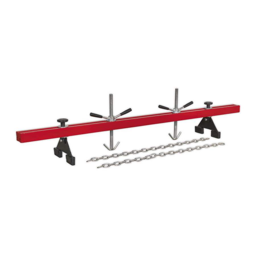
Note: numbers in brackets refer to item numbers shown in fig.1
3.1.
Insert a foot (5) into the slot in the standing block (4). Align the holes in
the two components and join them together using an M10 x 30 bolt (10).
3.2. Place a large washer (8) over the upstanding rod on the standing block
© Jack sealey limited
InstructIons For:
ENGINE SUPPORT BEAM
500kg CAPACITY, DOUBLE SUPPORT
ES502.V2
Model no:
(4) and insert the rod through the slot in the main support guide from
underneath. Place a large washer (7) over the thread on top of the rod
and secure the assembly to the main support guide by screwing on a grip
knob (6) as shown in fig.1. Assemble the other foot/standing block and fix
the assembly to the other end of the main guide beam in the same way.
3.3.
drop a large washer (8) over adjustable screw (3) and screw lift
handle (2) onto the top of the adjustable screw. screw the lift handle
approximately half way down the threads. Make up the second
adjustable screw in the same way and have both assemblies ready to
drop through the slot in the main guide beam after the beam has been
placed over the engine bay.
3.4.
the chains should also be attached when the guide beam is mounted
over the engine.
4. OPERATION
4.1.
the fully assembled support beam is very heavy and should be lifted into
place by two people.
4.2.
loosen the grip knobs (6) to allow the assemblies to slide and then locate
the rubber feet into the gutters of the vehicle's front wing panels or close
to the suspension strut towers.
Note: refer to the manufacturer's handbook to identify engine lifting brackets.
4.3.
drop the adjustable screw assemblies through the slot in the main beam
in positions adjacent to the engine lifting points
4.4.
Attach the ends of the chain to the lifting brackets on the engine.
4.5.
the chains may be attached to the lifting hooks in a single or looped
chain configuration.
4.6.
lower the adjustable screws and hook the chains around the hooks. In all
cases ensure that at least one link of the chain is hooked over the lifting
hooks.
4.7.
tighten both grip knobs (6).
4.8.
Progressively rotate the lifting handles (2) clockwise to tighten the chains
and support the engine.
4.9.
on completion of the maintenance task, rotate the lifting handles
anticlockwise to release the tension on the chains.
4.10. unhook the chains, loosen both grips (6) and remove the engine support
from the vehicle.
4.11.
remove the chains from the engine lifting points.
Original Language Version
fig.1
es502.V2
Issue no.1 - 27/06/13
Advertisement

Related Manuals for Sealey ES502.V2


Summary of Contents for Sealey ES502.V2
- Page 1 InstructIons For: ENGINE SUPPORT BEAM 500kg CAPACITY, DOUBLE SUPPORT Thank you for purchasing a Sealey Product. Manufactured to a high ES502.V2 standard this product will, if used according to these instructions and Model no: properly maintained, give you years of trouble free performance.
- Page 2 Washer 22mm Internal Ø chain M10 x 30 Bolt 16mm & locknut Parts support is available for this product. to obtain a parts listing and/or a diagram please log on to: www.sealey.co.uk, email: sales@sealey.co.uk or phone: 01284 757500 Environmental Protection.