Advertisement
Quick Links
Thank you for purchasing a Sealey Product. Manufactured to a high standard this product will, if used according to these instructions
and properly maintained, give you years of trouble free performance.
IMPORTANT: PLEASE READ THESE INSTRUCTIONS CAREFULLY. NOTE THE SAFE OPERATIONAL REQUIREMENTS,
WARNINGS AND CAUTIONS. USE THIS PRODUCT CORRECTLY AND WITH CARE FOR THE PURPOSE FOR WHICH IT IS
INTENDED. FAILURE TO DO SO MAY CAUSE DAMAGE AND/OR PERSONAL INJURY AND WILL INVALIDATE THE
WARRANTY. PLEASE KEEP INSTRUCTIONS SAFE FOR FUTURE USE.
1. SAFETY INSTRUCTIONS
DO NOT use the bore scope if dropped and/or damaged
7
DO NOT operate near live electrical wires.
7
DO NOT operate near moving parts such as pulleys, motors, gears or fans etc.
7
DO NOT bend the bore scope shaft tighter than 13cm diameter.
7
DO NOT expose the bore scope housing to water or other liquids.
7
DO NOT insert the bore scope shaft into locations whose temperature is greater than 55°C.
7
Maintain the bore scope in good and clean condition for best and safest performance.
A full range of personal safety equipment is available from your Sealey dealer.
Wear suitable clothing to avoid snagging. Do not wear jewellery and tie back long hair.
Account for all tools and parts being used and do not leave any in, or near, the engine.
Be alert to your surrounding environment while using the bore scope.
Note the location of the object to be inspected and determine a route to it. Bend the
bore scope shaft to follow the route.
2. INTRODUCTION
Suitable for internal inspection of modern small diesel engines where access to the cylinder
can be quickly made through the aperture left by removal of the glow plug. Inspection of this
type can avoid costly and unnecessary dismantling of the cylinder head. Features an
obedient probe with an illuminated camera head diameter of just 4.5mm – suitable for most small
engine applications. Rugged hand-set with IP64 dust/water rating includes controls for the LED probe
lighting and camera zoom. Live images from the camera head are displayed on a crystal clear screen
and may be viewed/saved externally using the AV cable supplied.
Optional Ø3.9mm probes in either forward view or side view configuration are available.
Uses 4 x AA batteries (supplied).
3. SPECIFICATION
Shaft Length . . . . . . . . . . . . . . . . . . . . . . . . . . . . . . . . . . . . . . . . .900mm
Minimum Bend Diameter . . . . . . . . . . . . . . . . . . . . . . . . . . . . . . .13cm
Probe Size . . . . . . . . . . . . . . . . . . . . . . . . . . . . . . . . . . . . . . . . . .4.5 x 1100mm
Screen Size . . . . . . . . . . . . . . . . . . . . . . . . . . . . . . . . . . . . . . . . .48 x 56mm
Resolution. . . . . . . . . . . . . . . . . . . . . . . . . . . . . . . . . . . . . . . . . . .320 x 240 pixels
Batteries . . . . . . . . . . . . . . . . . . . . . . . . . . . . . . . . . . . . . . . . . . . .4 x AA
Accessories . . . . . . . . . . . . . . . . . . . . . . . . . . . . . . . . . . . . . . . . .Mirrors - 70°, 90°, 110°
. . . . . . . . . . . . . . . . . . . . . . . . . . . . . . . . . . . . . . . . . . . . . . . . . . .Magnetic pick up
. . . . . . . . . . . . . . . . . . . . . . . . . . . . . . . . . . . . . . . . . . . . . . . . . . .Hook
Optional Probe (3.9 x 800mm) . . . . . . . . . . . . . . . . . . . . . . . . . . .VSBSP39F
Optional Probe (3.9 x 800mm) Side View . . . . . . . . . . . . . . . . . .VSBSP39S
4. PREPARATION
4.1
Batteries
4.1.1
Turn the bore scope over and lift up the ring screw (fig.2A) turn the ring
anti-clockwise until fully unscrewed and pull to lift open the battery door (fig.2B).
4.1.2
Insert AA batteries ensuring correct polarity (fig.2C).
4.1.3
Close the battery door screw in the ring screw clockwise until tight and push down
out of the way (fig.2D).
4.2
Probe
4.2.1
Pull back the threaded sleeve on the end of the probe and ensure the red dot
on the tab is facing upwards (fig.3A), take the probe and insert it into the top of
the bore scope housing.
The probe will only connect one way.
4.2.2
With the probe pushed firmly in, screw the sleeve onto the housing to secure
it in place (fig.3B).
4.3
Probe Attachments
4.3.1
There are five attachment for this bore scope, a hook, a magnet and 3 angled
mirrors (fig.4).
4.3.2
Each attachment is connected the same way - by screwing onto the threaded
end of the probe.
INSTRUCTIONS FOR:
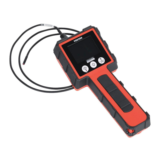
VIDEO BORE SCOPE 4.5mm
MODEL No:
fig.2
fig.3
Original Language Version
VS8200
fig.1
fig.4
VS8200
Issue: 1 - 08/03/11
Advertisement

Summary of Contents for Sealey VS8200
- Page 1 VS8200 MODEL No: Thank you for purchasing a Sealey Product. Manufactured to a high standard this product will, if used according to these instructions and properly maintained, give you years of trouble free performance. IMPORTANT: PLEASE READ THESE INSTRUCTIONS CAREFULLY. NOTE THE SAFE OPERATIONAL REQUIREMENTS, WARNINGS AND CAUTIONS.
- Page 2 Dispose of batteries according to local authority guidelines. Under the Waste Batteries and Accumulators Regulations 2009, Jack Sealey Ltd are required to inform potential purchasers of products containing batteries (as defined within these regulations), that they are registered with Valpak’s registered compliance scheme.