Hitachi CP-X505 Service Manual
Hide thumbs
Also See for CP-X505:
- Service manual (104 pages) ,
- User manual – operating manual (69 pages) ,
- User's manual and operating manual (19 pages)
Table of Contents
Advertisement
Quick Links
SERVICE MANUAL
Warning
The technical information and parts shown in this
manual are not to be used for: the development,
design, production, storage or use of nuclear, chemical,
biological or missile weapons or other weapons of
mass destruction; or military purposes; or purposes that
endanger global safety and peace. Moreover, do not
sell, give, or export these items, or grant permission for
use to parties with such objectives. Forward all inquiries
to Hitachi Ltd.
Be sure to read this manual before servicing. To assure safety from fi re, electric shock, injury, harmful
radiation and materials, various measures are provided in this Hitachi Multimedia LCD Projector. Be
sure to read cautionary items described in the manual to maintain safety before servicing.
1. When replace the lamp, to avoid burns to your fi ngers. The lamp becomes too hot.
2. Never touch the lamp bulb with a fi nger or anything else. Never drop it or give it a shock. They may
cause bursting of the bulb.
3. This projector is provided with a high voltage circuit for the lamp. Do not touch the electric parts of
power unit (circuit) and power unit (ballast), after turn on the projector.
4. Do not touch the exhaust fan, during operation.
5. The LCD module assembly is likely to be damaged. If replacing to the LCD LENS/PRISM assembly,
do not hold the FPC of the LCD module assembly.
6. Use the cables which are included with the projector or specifi ed.
1. Features ------------------------------------------------------ 2
2. Specifi cations ----------------------------------------------- 2
3. Names of each part ---------------------------------------- 3
4. Adjustment --------------------------------------------------- 6
5. Troubleshooting ------------------------------------------ 13
6. Service points --------------------------------------------- 20
7. Wiring diagram -------------------------------------------- 38
SPECIFICATIONS AND PARTS ARE SUBJECT TO CHANGE FOR IMPROVEMENT.
Multimedia LCD Projector
All manuals and user guides at all-guides.com
Caution
Service Warning
Contents
8. Disassembly diagram ----------------------------------- 49
9. Replacement parts list ---------------------------------- 58
10.RS-232C communication ------------------------------- 59
11. Block diagram --------------------------------------------- 72
12. Connector connection diagram ----------------------- 73
13.Basic circuit diagram ------------------------------------ 74
September 2006
No.0577E
YK
CP-X505(EDX35N)
Advertisement
Table of Contents

Related Manuals for Hitachi CP-X505


Summary of Contents for Hitachi CP-X505
-
Page 1: Table Of Contents
Be sure to read this manual before servicing. To assure safety from fi re, electric shock, injury, harmful radiation and materials, various measures are provided in this Hitachi Multimedia LCD Projector. Be sure to read cautionary items described in the manual to maintain safety before servicing. -
Page 2: Features
All manuals and user guides at all-guides.com CP-X505(EDX35N) 1. Features • High Brightness • Remote Control Via Your Web Browser • Compact Body • Rich Connectivity • Low Noise 2. Specifications Drive system TFT active matrix Liquid crystal Panel size 20mm(0.79 type) -
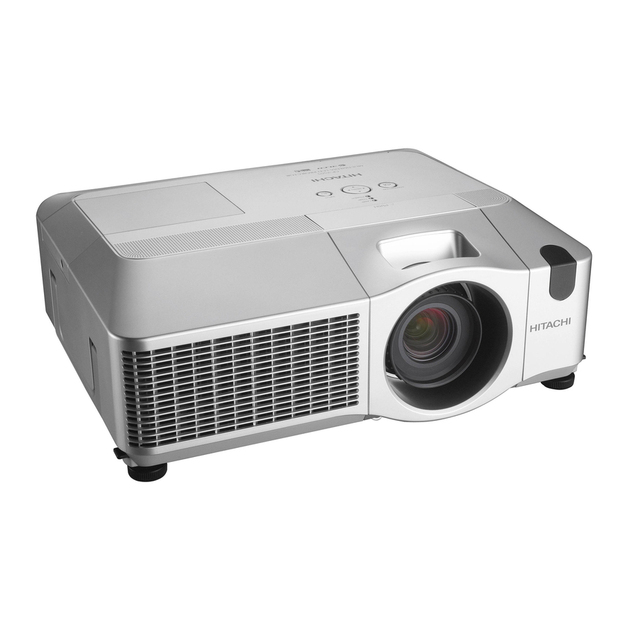
Page 3: Names Of Each Part
All manuals and user guides at all-guides.com CP-X505(EDX35N) 3. Names of each part ● Projector HOT! (1) Speakers (x 4) (2) Focus ring (20) (3) Zoom ring (11) (4) Lamp cover The lamp unit is inside. (15) (5) Lens shift cover... - Page 4 All manuals and user guides at all-guides.com CP-X505(EDX35N) Control panel (1) STANDBY/ON button (2) MENU button It consists of four cursor buttons. (3) INPUT button (4) POWER indicator (5) TEMP indicator (6) LAMP indicator Rear panel (1) Shutdown switch (2) Security slot...
- Page 5 All manuals and user guides at all-guides.com CP-X505(EDX35N) Remote control LASER (1) Laser pointer INDICATOR STANDBY/ON VIDEO It is a beam outlet. (2) LASER INDICATOR (3) LASER button (4) STANDBY/ON button (17) BLANK LASER (5) VOLUME button (6) MUTE button...
-
Page 6: Adjustment
All manuals and user guides at all-guides.com CP-X505(EDX35N) 4. Adjustment 4-1 Before adjusting 4-1-1 Selection of adjustment When any parts in the table 4-1 are changed, choose the proper adjusting items with the chart. Table 4-1: Relation between the replaced part and adjustment... - Page 7 All manuals and user guides at all-guides.com CP-X505(EDX35N) 4-2 Flicker adjustment (V.COM adjustment) Adjustment procedure Test pattern for the adjustment 1. Use DAC-P - V.COM - R: in the FACTORY MENU to adjust so that the flicker at the center of the screen is less than the flicker at the periphery.
- Page 8 All manuals and user guides at all-guides.com CP-X505(EDX35N) 4-5 E-POS adjustment (vertical bars adjustment 2) Test pattern for the adjustment Adjustment procedure 1. Make this adjustment after completing the ad- justment in the section 4-4. 2. Use DAC -P - E-POS - R in the FACTORY MENU and use it so that vertical bars are minimized.
- Page 9 All manuals and user guides at all-guides.com CP-X505(EDX35N) 4-7 Color uniformity adjustments Preparations 1. Perform these adjustments after the adjustments 5. Adjustment point No.1 should not be adjusted, described in the section 4-6. because it controls the brightness of the entire 2.
- Page 10 All manuals and user guides at all-guides.com CP-X505(EDX35N) Adjustment procedure 1 (When a color differential meter is used) Note: Since excessive correction may lead to a 1. First adjust the [MID-1] tone [G:]. correction data overview during internal 2. Select adjustment point [No.2][G:].
- Page 11 All manuals and user guides at all-guides.com CP-X505(EDX35N) Adjustment procedure 2 (visual inspection) 1. First adjust [MIN] tone [G:]. Adjustment technique: 2. Select [No.2] [G:]. First, adjust [B:] of the point whose color is to If the background is [G] monochrome, press the...
- Page 12 All manuals and user guides at all-guides.com CP-X505(EDX35N) 4-8 Adjusting the zoom and focus Focus ring Zoom ring 1. Use the zoom ring to adjust the screen size. 2. Use the focus ring to focus the picture. 4-9 Adjusting the lens shift 1.
-
Page 13: Troubleshooting
All manuals and user guides at all-guides.com CP-X505(EDX35N) 5. Troubleshooting Check points P501 P701 EE01... - Page 14 All manuals and user guides at all-guides.com CP-X505(EDX35N) Power can not be turned on *: Be sure to unplug the power cord before measuring resistance. voltage Measure supplied at pins resistance* between 0Ω (9),(12) and (14) of E800 on pins (9) and (14), and...
- Page 15 All manuals and user guides at all-guides.com CP-X505(EDX35N) Lamp does not light *: Be sure to unplug the power cord before measuring resistance. What is the state of Blinks Light LAMP indicator DK03 during operation? Is the Measure LAMP installation...
- Page 16 All manuals and user guides at all-guides.com CP-X505(EDX35N) Picture is not displayed when the RGB signal is input Confirm the splash screen the LCD Panels CPC36 connector and the user menu displayed connection to the MAIN correctly? board. PWB assembly MAIN...
- Page 17 All manuals and user guides at all-guides.com CP-X505(EDX35N) No sound Check at operating mode (Make sure the state of MUTE , Volume and AUDIO-SPEAKER) Disconnect the speaker from the infinity PWB assembly Main and Speaker measure its resistance. about 8...
- Page 18 All manuals and user guides at all-guides.com CP-X505(EDX35N) Can’t communicate with computer via NETWORK terminal. Check at operating mode Does the Lamp Is the computer Make sure NETWORK on lower right of the connected with the hardware Network connector light...
- Page 19 All manuals and user guides at all-guides.com CP-X505(EDX35N) Time in not correctly displayed. DATE AND TIME is displayed as 2000/1/1 0:00 in INFORMATION on NETWORK menu. Is TIME Set the time in DIFFERENCE on Set the time. Was the time set before?
-
Page 20: Service Points
All manuals and user guides at all-guides.com CP-X505(EDX35N) 6. Service points 6-1 Lead free solder [CAUTION] This product uses lead free solder (unleaded) to help preserve the environment. Please read these instructions before attempting any soldering work. CAUTION Always wear safety glasses to prevent fumes or molten solder from getting into the eyes. Lead free solder can splatter at high temperatures (600˚C). - Page 21 Therefore, regarding these parts, you can either replace part, LCD/Lens prism assembly, or send the whole unit LCD/Lens prism assembly back to HITACHI, where we will replace the malfunctioning part, recondition the device and send it back to you.
- Page 22 All manuals and user guides at all-guides.com CP-X505(EDX35N) (4) Unscrew PWB assembly MAIN to make it free and disconnect the LCD panel flexible cables. Remove these screws Remove these 9 screws Flexible cables of LCD panel (5) Press and hold the switch S941 using an insulator during maintenance.
- Page 23 All manuals and user guides at all-guides.com CP-X505(EDX35N) 3. Maintenance point Swab Each color part has same construction. By using swab and air duster, you can easily remove dust from panel and opti- cal filter. Panel Holder Optical filter 4. Cleaning the panels and optical filters (1) Turn on the set and lit on the lamp.
- Page 24 5. Put a new battery in. “+” marking Replace battery with HITACHI MAXELL, Part No.CR2032 only. Use of another battery may present a risk of fire or explosion. Insert a new battery in the battery holder according to its minus terminal indicated in the battery holder, so that the side marked by + is facing.
- Page 25 All manuals and user guides at all-guides.com CP-X505(EDX35N) 6-4-2 Potting batteries into the remote control 1. Remove the battery cover. Slide back and remove the battery cover in the direction of the arrow. 2. Insert the batteries. Align and insert the two AA batteries according to their plus and minus terminals as indicated in the remote control.
- Page 26 All manuals and user guides at all-guides.com CP-X505(EDX35N) 6-5 Air filter WARNING • Before caring, make sure the power switch is off and the power cable is not plugged in, then allow the projector to cool suffi ciently. The care in a high temperature state of the projector could cause an electric shock, a burn and/or malfunction to the projector.
- Page 27 All manuals and user guides at all-guides.com CP-X505(EDX35N) 6-6 Lamp WARNING HIGH VOLTAGE HIGH TEMPERATURE HIGH PRESSURE ● The projector uses a high-pressure mercury glass lamp. The lamp can break with a loud bang, or burn out, if jolted or scratched, handled while hot, or worn over time. Note that each lamp has a different life- time, and some may burst or burn out soon after you start using them.
- Page 28 All manuals and user guides at all-guides.com CP-X505(EDX35N) Replacing the Lamp A lamp has a fi nite product life. Using the lamp for long periods of time could cause the pictures darker or the color tone poor. Note that each lamp has a different lifetime, and some may burst or burn out soon after being started using.
- Page 29 All manuals and user guides at all-guides.com CP-X505(EDX35N) 6-7 Lens WARNING • Before replacing the projector lens, be sure to read this manual, the “User's Manual-Safety Guide” and the “Optional Lens User's Manual” of the LCD projector for use with this lens.
- Page 30 All manuals and user guides at all-guides.com CP-X505(EDX35N) 6-8 Other care WARNING Before caring, make sure the power switch is off and the power cable is not plugged in, and then allow the projector to cool suffi ciently. The care in a high temperature state of the projector could cause a burn and/ or malfunction to the projector.
- Page 31 All manuals and user guides at all-guides.com CP-X505(EDX35N) 6-9 Notice of AUTO adjustment Use of AUTO adjustment with the image through RGB input optimizes V_POSI, H_POSI, H_SIZE and H_PHASE automatically. In case that projected image has dark tone around its peripheral, AUTO operation sometimes makes artifacts in the image, shifts capture area and so on.
- Page 32 All manuals and user guides at all-guides.com CP-X505(EDX35N) 6-10 How to inactivate the security functions This projector is equipped with security functions. (1)MyScreen PASSWORD The MyScreen PASSWORD function can be used to prohibit access to the MyScreen function and prevent the currently registered MyScreen image from being overwritten.
- Page 33 PIN BOX (ID Inquiring Code) 2. Send HITACHI sales company the Inquiring code (10 digits) to inquire the correct PIN code. 3. With the PIN BOX menu displayed, input the correct PIN code. Enter the correct PIN CODE that HITACHI sales company informed.
- Page 34 All manuals and user guides at all-guides.com CP-X505(EDX35N) 6-12 Related Messages When the unit’s power is on, messages such as those shown below may be displayed. When any such message is displayed on the screen, please respond as described below.
- Page 35 All manuals and user guides at all-guides.com CP-X505(EDX35N) 6-13 Regarding the indicator lamps Lighting and flashing of the POWER indicator, the LAMP indicator, and the TEMP indicator have the meanings as described in the table below. Please respond in accordance with the instructions within the table.
- Page 36 All manuals and user guides at all-guides.com CP-X505(EDX35N) 6-14 HIDDEN SERVICE MENU To display the OSD for “HIDDEN SERVICE MENU” set up. HIDDEN SERVICE By the control panel By the remote control transmitter AIR-SENSOR EXECUTE 1. Display the Advanced menu by 1.
- Page 37 All manuals and user guides at all-guides.com CP-X505(EDX35N) 6-16 Reset of the Network Web password / User ID, Network Control password ATTENTION : Performing this operation initializes the network settings. If the projector has the customized settings in the network, make a note of the network settings to restore them before this operation.
-
Page 38: Wiring Diagram
All manuals and user guides at all-guides.com CP-X505(EDX35N) 7. Wiring diagram... - Page 39 All manuals and user guides at all-guides.com CP-X505(EDX35N)
- Page 40 All manuals and user guides at all-guides.com CP-X505(EDX35N)
- Page 41 All manuals and user guides at all-guides.com CP-X505(EDX35N)
- Page 42 All manuals and user guides at all-guides.com CP-X505(EDX35N)
- Page 43 All manuals and user guides at all-guides.com CP-X505(EDX35N)
- Page 44 All manuals and user guides at all-guides.com CP-X505(EDX35N)
- Page 45 All manuals and user guides at all-guides.com CP-X505(EDX35N)
- Page 46 All manuals and user guides at all-guides.com CP-X505(EDX35N)
- Page 47 All manuals and user guides at all-guides.com CP-X505(EDX35N)
- Page 48 All manuals and user guides at all-guides.com CP-X505(EDX35N)
-
Page 49: Disassembly Diagram
All manuals and user guides at all-guides.com CP-X505(EDX35N) 8. Disassembly diagram M : Meter Screw T : Tapping Screw [ Remove UPPER CASE ] ( See Notice 1 ) T3X12 T3X12 T3X12 [ UPPER CASE assembly ] [ Remove Network unit ]... - Page 50 All manuals and user guides at all-guides.com CP-X505(EDX35N) M : Meter Screw T : Tapping Screw [ PANEL DUCT ] [ Remove Duct and Power unit ] [ FILTER UNIT ] - assembly - - assembly - T3X12 - Disassembly -...
- Page 51 All manuals and user guides at all-guides.com CP-X505(EDX35N) Notice 1. Detach and attach the upper case. Follow the procedure below to detach and attach the upper case. When disassembling a. Remove the Lamp door. CAUTION The lamp door must be removed before the upper case when disassembling the machine. If the upper case is detached with the lamp door installed, the MAIN board might be damaged.
- Page 52 All manuals and user guides at all-guides.com CP-X505(EDX35N) (2) Remove 2 screws on the front. (3) Remove the front cover. front cover 2 screws c. Remove 9 screws on the bottom and 2 screws on the rear to detach the upper case.
- Page 53 All manuals and user guides at all-guides.com CP-X505(EDX35N) When assembling a. Tighten 9 screws on the bottom and 2 screws on the rear after attaching the upper case with the lamp door separated. In order not to make a gap between the upper and the bottom cases, tighten these screws while pressing down the upper case in the direction of the arrow.
- Page 54 All manuals and user guides at all-guides.com CP-X505(EDX35N) c. Attach the Lamp door. Lamp door CAUTION Tighten this screw using a manual screwdriver. 2. Replacing the power units. Remove the screw to take off the duct. Remove the 3 screws to take off the power unit.
- Page 55 All manuals and user guides at all-guides.com CP-X505(EDX35N) 3. Detaching and attaching the Panel Fan Duct assembly When disassembling Remove 6 screws and unhook the panel fan duct assembly as shown in the diagram. Panel fan duct assembly When assembling...
- Page 56 All manuals and user guides at all-guides.com CP-X505(EDX35N) 4. Attaching the dichroic optics unit ④ Put the dichroic optics unit on the bottom case, and tighten screws in order of 1, 2, 3 and 4 as shown in the diagram.
- Page 57 All manuals and user guides at all-guides.com CP-X505(EDX35N) 7. Assembling the power unit CAUTION Make sure that power unit board was fi xed by 4 hooks of PWB HOLDER. Make sure that it is hard to remove. Cross Section 8. Assembling the FOOT MTL Remove the remote board first when assembling the FOOT MTL.
-
Page 58: Replacement Parts List
All manuals and user guides at all-guides.com CP-X505(EDX35N) 9. Replacement Parts list PRODUCT SAFETY NOTE : Components marked with a have special characteristics important to safety. Before replacing any of there components, read carefully, the PRODUCT SAFETY NOTICE of this Service Manual. Don't degrade the safety of the projector through improper servicing. -
Page 59: Rs-232C Communication
All manuals and user guides at all-guides.com CP-X505(EDX35N) 10. RS-232C communication RS-232C cable(Cross) CONTROL port RS-232C port of the projector of a computer - (1) (1) CD RD (2) (2) RD TD (3) (3) TD - (4) (4) DTR GND (5) - Page 60 All manuals and user guides at all-guides.com CP-X505(EDX35N) Requesting projector status (Get command) (1) Send the request code Header + Command data (‘02H’+‘00H’+ type (2 bytes)+ ‘00H’+‘00H’) from the computer to the projector. (2) The projector returns the response code ‘1DH’+ data (2 bytes) to the computer.
- Page 61 All manuals and user guides at all-guides.com CP-X505(EDX35N) Command data chart Command Data Names Operation Type Header Action Type Setting Code Power Turn off BE EF 06 00 2A D3 01 00 00 60 00 00 Turn on BE EF...
- Page 62 All manuals and user guides at all-guides.com CP-X505(EDX35N) Command Data Names Operation Type Header Action Type Setting Code User Gamma Pattern BE EF 06 00 FB FA 01 00 80 30 00 00 9 step gray scale BE EF 06 00...
- Page 63 All manuals and user guides at all-guides.com CP-X505(EDX35N) Command Data Names Operation Type Header Action Type Setting Code COLOR TEMP GAIN B BE EF 06 00 8C F5 02 00 B3 30 00 00 Increment BE EF 06 00 EA F5...
- Page 64 All manuals and user guides at all-guides.com CP-X505(EDX35N) Command Data Names Operation Type Header Action Type Setting Code ASPECT BE EF 06 00 9E D0 01 00 08 20 00 00 16:9 BE EF 06 00 0E D1 01 00...
- Page 65 All manuals and user guides at all-guides.com CP-X505(EDX35N) Command Data Names Operation Type Header Action Type Setting Code M1-D NORMAL BE EF 06 00 3E D9 01 00 20 20 00 00 ENHANCED BE EF 06 00 AE D8 01 00...
- Page 66 All manuals and user guides at all-guides.com CP-X505(EDX35N) Command Data Names Operation Type Header Action Type Setting Code VOLUME-Component BE EF 06 00 01 CC 02 00 65 20 00 00 Increment BE EF 06 00 67 CC 04 00...
- Page 67 All manuals and user guides at all-guides.com CP-X505(EDX35N) Command Data Names Operation Type Header Action Type Setting Code SRS WOW TURN OFF BE EF 06 00 CE FE 01 00 94 20 00 00 /SURROND-RGB2 BE EF 06 00 5E FF...
- Page 68 All manuals and user guides at all-guides.com CP-X505(EDX35N) Command Data Names Operation Type Header Action Type Setting Code AUDIO - M1-D TURN OFF BE EF 06 00 BA DD 01 00 33 20 00 00 Audio1 BE EF 06 00...
- Page 69 All manuals and user guides at all-guides.com CP-X505(EDX35N) Command Data Names Operation Type Header Action Type Setting Code LANGUAGE ENGLISH BE EF 06 00 F7 D3 01 00 05 30 00 00 FRANÇAIS BE EF 06 00 67 D2 01 00...
- Page 70 All manuals and user guides at all-guides.com CP-X505(EDX35N) Command Data Names Operation Type Header Action Type Setting Code AUTO SEARCH TURN OFF BE EF 06 00 B6 D6 01 00 16 20 00 00 TURN ON BE EF 06 00...
- Page 71 All manuals and user guides at all-guides.com CP-X505(EDX35N) Command Data Names Operation Type Header Action Type Setting Code MY BUTTON-2 RGB1 BE EF 06 00 C6 32 01 00 01 36 00 00 RGB2 BE EF 06 00 06 30...
-
Page 72: Block Diagram
All manuals and user guides at all-guides.com CP-X505(EDX35N) 11. Block diagram... -
Page 73: Connector Connection Diagram
All manuals and user guides at all-guides.com CP-X505(EDX35N) 12. Connector connection diagram C.VIDEO EC03 EC01 CNVID EV01 E301 SENSER C-Video Y(S-Video) E801 FAN1S Vcc(Cont PANEL-R/G) Cb/Pb Cr/Pr PANEL-B) EC05 Audio_L_Out VID-7 PANEL R/G/B EXHAUST) AUDIO-OUT WIRED_RC-IN VDDX ET01 ET03 CNCNT... -
Page 74: Basic Circuit Diagram
All manuals and user guides at all-guides.com CP-X505(EDX35N) 13. Basic circuit diagram Parts with hatching are not mounted. CONFIDENTIAL APU5 APUM APUP ET21 UBB-4R-D14C ET03 PH-03V-D RS232C ET01 3175-09M ET02 APRD APTD APT6 PH-05V-D USB D- USB D+ APT4 APSG... - Page 75 All manuals and user guides at all-guides.com CP-X505(EDX35N) CONFIDENTIAL FRONT-56 FRONT-38 UP-56 UP-38_( *IR04 IR03 *IR02 IR01 KSM-2003LM2EL KSM-2003LM2EL KSM-2003LM2EL KSM-2003LM2EL Vout Vout Vout Vout *CR10 CR07 *CR04 100p-C 100p-C 100p-C *RR08 RR02 2125 2125 CR01 100p-C ER01 ZH-06H PWB assembly REMOTE (EDX40N)
- Page 76 All manuals and user guides at all-guides.com CP-X505(EDX35N) MEMO...
- Page 77 All manuals and user guides at all-guides.com CONFIDENTIAL POWER UNIT (BALLAST) 1 (EDX35N)
- Page 78 All manuals and user guides at all-guides.com CONFIDENTIAL POWER UNIT (BALLAST) 2 (EDX35N)
- Page 79 All manuals and user guides at all-guides.com CONFIDENTIAL DC IN+ D201 C200 C108 FB105 T201 L102 L103 DC IN- IC200 D102 ICP200 R200 C202 CN104 FB106 D200 1 14.5V C201 R244 R245 R201 R111 C204 2 14.5V R125 C117 C203 C104 FB101 R202...
- Page 80 All manuals and user guides at all-guides.com CONFIDENTIAL F101 C101 L101 C100 C103 L100 R100 C102 POWER UNIT (CIRCUIT) 2 (EDX35N)
- Page 81 All manuals and user guides at all-guides.com EC03 CONFIDENTIAL YKC21-4673V APC20 CVBS LC01 NFL21SP407X1C3 2125 LC02 APC21 R1(SW) APC22 1608 APC23 APC24 LC03 NFL21SP407X1C3 2125 LC04 APC51 LC09 APC52 EC01 1608 NFL21SP407X1C3 ZH-09V APC1 2125 LC10 CVBS NFL21SP407X1C3 APC2 2125 APC25 LC05 APC3...
- Page 82 All manuals and user guides at all-guides.com CONFIDENTIAL TEMP DK02 SML-210VT RK23 QK23 1005 DTC114EUA EK01 ZH-12H RK01 APY01 KEYO-0 LAMP DK03 RK02 APY02 SML-210VT KEYO-1 RK24 APY03 QK24 DTC114EUA 1005 RK04 APY04 KEYI-0 RK05 APY05 KEYI-1 RK06 APY06 KEYI-2 RK07 APY07 QK22...
- Page 83 All manuals and user guides at all-guides.com CONFIDENTIAL C2H1 C2H2 18p-C 15p-C 1005 1005 R2R8 R2N1 1.0K RESETN R215 1005 1005 R2N2 1.0K 1.0K 1.0M Q201 1005 I201 1005 DTC114EE MISC PW288B-10L R216 EMU-RESET L201 600 R2F0 I201 RESETB 1005 1608 R240 INPUT PORT 0...
- Page 84 All manuals and user guides at all-guides.com CONFIDENTIAL L251 65mA +3.3V 1608 N251 R263 1.0K-1% I251 1005 S29AL016D70TFI010 I201 MAIN MEMORY PORT PW288B-10L GND1 BYTE# MVREF MREFIN0 R254 C253 C262 I252 I253 Vss-46 MREFIN1 0.1/10 0.1/10 R2E3 EDD2516AKTA-6B EDD2516AKTA-6B R266 1005 MCK0 2010...
- Page 85 All manuals and user guides at all-guides.com CONFIDENTIAL 38_REAR 56_REAR I001 *I002 KSM-2003LM2EL KSM-2003LM2EL Vout Vout *C004 R001 100p-C +3.3V C001 100p-C R308 S310 +6.6V 6.6V 1005 I301 SKHHLMA010 S-80950CNMC-G9LT2G 3.3V R311 3.3V R303 3.3V RESETN Q302 R309 I302 1005 DTC114EE SN74LVC1G97DCK R306...
- Page 86 All manuals and user guides at all-guides.com CONFIDENTIAL I801 I808 SI-3010KM BD00KA5WFP-E2 L8A1,L802-805 1.2V-TG L816 15.5V-Panel C823 0.033/16 +4.0V C6-K3LA 1.8V-CPU +17V +1.8VCPU FANGND 1005 I807 FAN15V TPS40222DR 3.3V-Panel 3.3V-CPU PVIN R829 (AUDIO POWER SUPPLY) L8A1 E806 APP7 C1V222-2A AVIN PH-05V 1005 3216...
- Page 87 All manuals and user guides at all-guides.com CONFIDENTIAL I401 L401 L3E07110K0A L3E07110K0A 1/4 2518 +3.3VP +1.2V VDD1-D7 L402 VDD1-D8 C421 VDD1-D9 2.2/6.3 2518 VDD1-D10 HRESET0 CHHRST C422 VDD1-D11 VRESET0 CHVRST 0.01/16 VDD1-D12 HPLL CHHPLL 1005 VDD1-D13 CLP1 CHCP1 C423 R442 VDD1-E7 CLP2 CHCP2...
- Page 88 All manuals and user guides at all-guides.com CONFIDENTIAL EDX R Panel Part +3.3VP +15.5V SHCLKR SHCLKR DIRXR DIRXR ENBXR1 ENBXR1 ENBXR5 P501 ENBXR5 54104-36HUp DXOUTR DXOUTR CLXOUTR CLXOUTR DYOUTR APR36 DYOUTR CLYOUTR RLCCOM CLYOUTR LCCOM ENBYR1 APR35 ENBYR1 ENBYR2 ENBYR2 VDDY APR34 XFRR...
- Page 89 All manuals and user guides at all-guides.com CONFIDENTIAL EDX G Panel Part +3.3VP +15.5V SHCLKG SHCLKG DIRXG DIRXG ENBXG1 ENBXG1 ENBXG5 P601 ENBXG5 54104-36HUp DXOUTG DXOUTG CLXOUTG CLXOUTG DYOUTG APG36 DYOUTG CLYOUTG GLCCOM CLYOUTG LCCOM ENBYG1 APG35 ENBYG1 ENBYG2 ENBYG2 VDDY APG34 XFRG...
- Page 90 All manuals and user guides at all-guides.com CONFIDENTIAL EDX B Panel Part +3.3VP +15.5V SHCLKB SHCLKB DIRXB DIRXB ENBXB1 P701 ENBXB1 ENBXB5 54104-36HUp ENBXB5 DXOUTB DXOUTB CLXOUTB CLXOUTB DYOUTB APB36 DYOUTB CLYOUTB BLCCOM CLYOUTB LCCOM ENBYB1 APB35 ENBYB1 ENBYB2 ENBYB2 VDDY APB34 XFRB...
- Page 91 All manuals and user guides at all-guides.com CONFIDENTIAL R186 1005 RESETN R103 100 1 R102 I2CCLK R171 100 1 1005 I2CDAT 1005 1005 R172 4.7K LPF_RGB 1005 R173 4.7K LPF OFF 1005 LPF ON R140 LPF_RGB R187 1005 R141 1005 IN1CST R142 1005...
- Page 92 All manuals and user guides at all-guides.com CONFIDENTIAL HV_Sel Wireless(In1) VideoDecorder(In0) Buffer D+3.3V IV07 SN74LVC1G126DCK TV06 D+1.5V D+3.3V LV07 RV51 CV66 LV06 CV69 CV67 CV68 0.1/10 2518 CV07 CV08 0.1/10 0.1/10 0.1/10 1005 2518 0.1/10 10/10 1005 1005 1005 1005 1005 2125 LV01...
- Page 93 APIG2 *LS11 INC+ INC- 560-1% QS01 2125 RGB IN 2 RS82 SC200JT DTC114EE 1005 2125 CS20 L:RGB1/H:RGB2 1005 RS84 3.0p-C For Hitachi Model APIR2 *LS12 RGB1/2 SC200JT 1005 2125 GND1 GND1 RS18 GND1 RS19 Selector IS04 SN74LVC1G97DCK RSA0 1005 GND1...
- Page 94 All manuals and user guides at all-guides.com CONFIDENTIAL DG11 RB521G-30 *RGB2 3.3V 2010 3.3V *DG12 I0RO7 3.3V 3.3V RB521G-30 I0RO6 5.0V 3.3V 3.3V DDC_5V 3.3V 3.3V I0RO5 *RG77 5.0V 5.0V 0.8V 3.3V 3.3V I0RO4 I0RO3 RG13 3.3V 3.3V RG73 1005 CG40 *CG21 I0RO2...
- Page 95 All manuals and user guides at all-guides.com CONFIDENTIAL 5.0V IW02 DS14C232CM CW57 +6.6V 0.1/10 1005 Dout1 IW53 RW97 uPD168110 8.0V Rin1 3.3V 3.0V 3.3V MODE RESETB 3.3V 1005 EW04 8.0V RW04 Rout1 3.3V PH-03V 8.0V 1005 8.0V 8.0V Din1 RW17 LGND RW05 8.0V...
- Page 96 All manuals and user guides at all-guides.com CONFIDENTIAL 3.3V Sheet 1 Sheet 1 SP_OFF 14.5V Sheet 4 +14.5V CA99 47/25 8.5V MVK/SKV Audio Power GND TP007 TP001 4.4V P_GND RAK0 0.0V 0.0V 8.4V 8.4V 4.4V IA01 1005 APAL1 BD3883FS 0.0V APAR1 8.5V VIN1...
- Page 97 All manuals and user guides at all-guides.com CONFIDENTIAL Hitachi ASK_Proxima +3.3V Reserved(I/F) 1005 Reserved(I/F) 0.1/10 *LE03 RE71,RE72,RE73,RE74 put side-B (soldering side) SC200JT CE16 IE03 *RE71 2125 3.3V *LE01 SN74LVC1G97DCK OEM_ID0 *REF6 1005 SC200JT 3.3V 1005 3.3V 2125 OEM_ID1 *LE04 *RE72...
- Page 98 All manuals and user guides at all-guides.com CONFIDENTIAL PWB assembly NETWORK 1 (EDX35N)
- Page 99 All manuals and user guides at all-guides.com CONFIDENTIAL PWB assembly NETWORK 2 (EDX35N)
- Page 100 All manuals and user guides at all-guides.com CONFIDENTIAL PWB assembly NETWORK 3 (EDX35N)
- Page 101 All manuals and user guides at all-guides.com CONFIDENTIAL PWB assembly NETWORK 4 (EDX35N)
- Page 102 All manuals and user guides at all-guides.com MEMO...
- Page 103 All manuals and user guides at all-guides.com CP-X505(EDX35N) Basic circuit diagram list PWB assembly CONTROL PWB assembly MAIN 6 PWB assembly BATTERY PWB assembly MAIN 7 PWB assembly REMOTE PWB assembly MAIN 8 PWB assembly SW PWB assembly MAIN 9...
- Page 104 All manuals and user guides at all-guides.com CP-X505 YK No.0577E QR70101 Printed in Japan (JE)