
Related Manuals for Siemens FDM275-O


Summary of Contents for Siemens FDM275-O
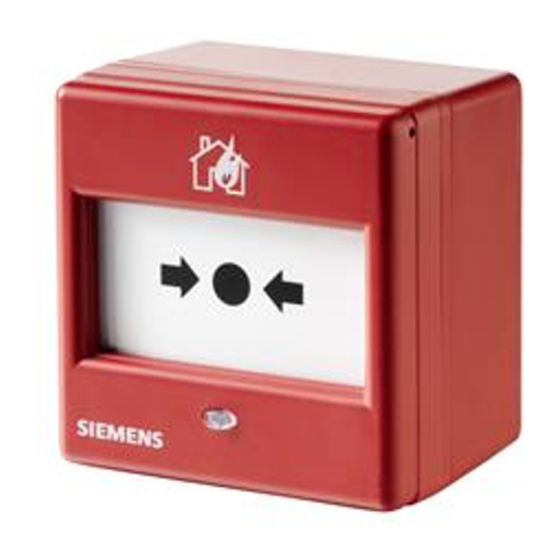
- Page 1 FDM275-O Radio manual call point Mounting Smart Infrastructure A6V10425655_en--_g 2020-03-31...
- Page 2 All rights created by patent grant or registration of a utility model or design patent are reserved. Issued by: Siemens Switzerland Ltd. Smart Infrastructure Global Headquarters Theilerstrasse 1a CH-6300 Zug Tel. +41 58 724-2424 www.siemens.com/buildingtechnologies Edition: 2020-03-31 Document ID: A6V10425655_en--_g © Siemens Switzerland Ltd, 2015 2 | 16 A6V10425655_en--_g...
-
Page 3: Table Of Contents
Table of contents About this document................. Mounting and installation................Mounting radio manual call point FDM275-O ........... Installation ....................Installing the protective cover ..............Replacing the plastic insert with a glass insert ......... Details for ordering ................... Battery pack BAT3.6-10 ................ - Page 4 4 | 16 A6V10425655_en--_g...
-
Page 5: About This Document
1 About this document Overview The FDM275-O radio manual call point is intended for use in areas of a house where a fire can be detected by people who can manually trigger an alarm. The radio manual call point FDM275-O consists of a back box, a switching unit, and a battery pack. -
Page 6: Mounting And Installation
Mounting radio manual call point FDM275-O 2 Mounting and installation 2.1 Mounting radio manual call point FDM275-O Secure the radio manual call point FDM275-O at a height of 0.9…1.6 m on an even surface. Observe the country-specific regulations for the exact mounting height! Figure 1: Opening the housing with the key FDMK295 The position of radio manual call point FDM275-O has been established. -
Page 7: Installation
1. Remove the adhesive label with the serial number from the type plate (3) on the switching unit. Use the adhesive label to mark the position of the radio manual call point FDM275-O on the device location plan. 2. Label the battery pack (2) with the current date. - Page 8 If it flashes red, this indicates the factory setting. – If it flashes green, this indicates that the radio manual call point FDM275-O has already been logged on to a radio gateway. If this does not happen, this means the battery pack is defective and must not be used.
-
Page 9: Installing The Protective Cover
Snap the protective cover FDMC295 (2) into place in the recesses in the housing cover (1) intended for this purpose. See also 'Protective cover FDMC295' chapter. a The protective cover is installed. Figure 3: Installing the protective cover FDMC295 1 Radio manual call point FDM275-O 2 Protective cover A6V10425655_en--_g 9 | 16... -
Page 10: Replacing The Plastic Insert With A Glass Insert
Mounting and installation Replacing the plastic insert with a glass insert 2.4 Replacing the plastic insert with a glass insert Proceed as follows to replace the plastic insert with a glass insert: The detector line to which the manual call point is connected is switched off. 1. -
Page 11: Details For Ordering
● Inscription field for commissioning date ● Compatible with: – Radio manual call point FDM273-O – Radio manual call point FDM275-O – Radio fire detector FDOOT271-O ● Order number: S54370-Z11-A1 3.2 Protective cover FDMC295 ● For protection against unintended alarm activation ●... -
Page 12: Plastic Insert Fdmp295
3.4 Plastic insert FDMP295 ● For alarm activation and protection against soiling ● Compatible with: – Radio manual call point FDM275-O ● Order number: A5Q00013445 3.5 Key FDMK295 ● For testing and resetting manual call points ● For removing the housing cover from the back ●... -
Page 13: Specifications
Specifications Technical data 4 Specifications 4.1 Technical data You will find information on approvals, CE marking, and the relevant EU directives for this device (these devices) in the following document(s); see 'Applicable documents' chapter: ● Document A6V10431682 Device characteristics Detector diagnosis With FXS2061-O Wireless diagnostic tool or connected fire control panel Type of alarm activation... - Page 14 Specifications Technical data Ambient conditions Place of installation Inside buildings/indoors Operating temperature -10…+55 °C Storage temperature -30…+75 °C Air humidity ≤95 % rel. Protection categories (IEC 60529): IP24D Electromagnetic compatibility: ● 10 kHz…100 kHz 160 V/m ● 100 kHz…2.5 GHz 30 V/m Mechanical data Weight: 0.216 kg Housing material Red => Polycarbonate (PC) Black => Acrylonitrile butadiene styrene (ABS) Housing color ~RAL 3000 flame red...
-
Page 15: Dimensions
Specifications Dimensions 4.2 Dimensions 86.8 36.5 4.3 Master gauge for recesses 25.4 25.4 A, B = 5.3 mm 4.4 Environmental compatibility and disposal This equipment is manufactured using materials and procedures which comply with current environmental protection standards as best as possible. - Page 16 © Siemens Switzerland Ltd, 2015 Issued by Siemens Switzerland Ltd Technical specifications and availability subject to change without notice. Smart Infrastructure Global Headquarters Theilerstrasse 1a CH-6300 Zug +41 58 724 2424 www.siemens.com/buildingtechnologies A6V10425655_en--_g...