Table of Contents
Advertisement
Quick Links
Wired Controller
Installation and Operation Manual
ACT17CWA
Table of Contents
Parts and Functions
Interface Display
Icons
. . . . . . . . . . . . . . . . . . . . . . . . . . . . . . . . . . . . . . . . . . . . . 2
Dip Switch
. . . . . . . . . . . . . . . . . . . . . . . . . . . . . . . . . . . . . . . . . 4
Operation
Mode Key
. . . . . . . . . . . . . . . . . . . . . . . . . . . . . . . . . . . . . . . . . 6
Fan Key
. . . . . . . . . . . . . . . . . . . . . . . . . . . . . . . . . . . . . . . . . . . . . . . 6
Temperature Adjustment Keys
Special Function
Special Function Selection
Installer Settings
Adjust ECO Parameters
Child Lock
. . . . . . . . . . . . . . . . . . . . . . . . . . . . . . . . . . . . . . . . 10
Lock Settings
Fahrenheit / Celsius
Temperature Compensation
Forced Defrost/Cooling/Heating
Error Checks
Mode Restriction
Mode Combination Settings
Wiring Instruction
• Please read this manual before use
• Please keep this manual for future reference.
. . . . . . . . . . . . . . . . . . . . . . . . . . . . . . . . . . . . 1
. . . . . . . . . . . . . . . . . . . . . . . . . . . . 8
. . . . . . . . . . . . . . . . . . . . . . . . . . . . . 10
. . . . . . . . . . . . . . . . . . . . . . . . . . . . . . . . . . . . . . 11
. . . . . . . . . . . . . . . . . . . . . . . . . . . . . . . . 11
. . . . . . . . . . . . . . . . . . . . . . . . . . 12
. . . . . . . . . . . . . . . . . . . . . . . . . . . . . . . . . . . . . . 13
. . . . . . . . . . . . . . . . . . . . . . . . . . . . . . . . . . 14
. . . . . . . . . . . . . . . . . . . . . . . . . . 15
. . . . . . . . . . . . . . . . . . . . . . . . . . . . . . . . . . . 15
. . . . . . . . . . . . . . . . . . . . . . . . . 7
. . . . . . . . . . . . . . . . . . . . . . . 12
49-5000395 Rev. 5
GEA 08-21
Advertisement
Table of Contents

Related Manuals for GE ACT17CWA


Summary of Contents for GE ACT17CWA
- Page 1 Wired Controller Installation and Operation Manual ACT17CWA Table of Contents Parts and Functions Interface Display ........1 Icons .
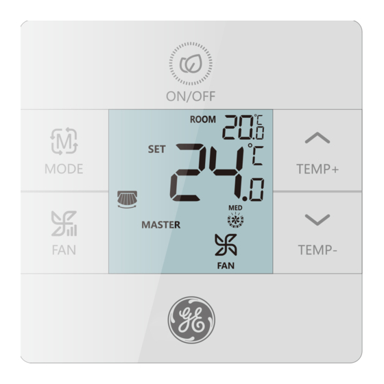
- Page 2 Parts and Functions Interface Display MAIN Full Display...
- Page 3 Parts and Functions Icons Room temperature display (dip switch SW1-2 on). Set temperature display Filter HRV (Heat Reclaim Ventilation), if HRV function is set, it will display this icon Error icon displays detected fault ECO mode on Central/lock when connected to a central controller UP/DOWN louver swing LEFT/RIGHT louver swing...
- Page 4 Parts And Functions MAIN / SUB Main / Subordinate wired controller Quiet Fan Speed (some models) Low Fan Speed Medium Fan Speed High Fan Speed Turbo Fan Speed (some models) Auto Fan speed is indicated by the display automatically stepping from low to high repeatedly. Auto Mode Cooling Mode Heating Mode...
- Page 5 Dip Switch Dip Switch SW1 Default Sw1-1 Subordinate wired Main wired controller controller Room temperature Sw1-2 Room temperature display on Sw1-3 Room temperature Room temperature collected from indoor unit collected from controller Auto restart after power Sw1-4 power loss loss Old protocol (models Sw1-5 New protocol...
- Page 6 Dip Switch Dip Switch SW2 Default Sw2-1 Mode Lock Normal Sw2-2 still sound when command is sent by Tone on wireless remote. Sw2-3 Reserved Reserved Sw2-4 Reserved Reserved Initialization tween the Room Temperature display and the Set Temperature display until communication is established with the indoor unit. Audible Alert Press to power ON or power OFF the control.
- Page 7 Mode Key / Fan Key Mode key: • Each press of the MODE button will change the operating mode from • Each mode has its initial default fan speed. Mode Fan speed Temperature Auto Auto 76°F Cool High 76°F Initial Heat Auto 76°F...
- Page 8 Temperature Temperature Adjustment Keys: • Press the TEMP+ or TEMP- keys to change the temperature by 1°F increments. • The temperature set point range for Auto, Cooling, Heating then temperature range will change per the ECO setting parameters). • The temperature is set independently under Auto, Cooling, Heating and Dehumidify modes.
- Page 9 Function Selection Special Function Selection: With the control powered on, press and hold the TEMP+ for 5 seconds to enter the special function menu. All the special function icons will display. Use the TEMP+ and TEMP- buttons to move between icons. Use FAN button to select function.
- Page 10 Function Selection...
- Page 11 Installer Settings Adjust ECO Parameters: • Cooling: Power on the unit. Adjust set temperature to 86°F. Press and hold FAN and TEMP+ for 5 seconds. The minimum allowable set temperature will be displayed in the top right corner. Use TEMP+/- to change the parameter, then press FAN save.
- Page 12 Lock Settings / Fahrenheit Setting Central/Lock Function: Function is active only when system has a central control, such as the YCZ-A004. This setting is activated only by the central Control. Central Control Central Lock No functions available. Fahrenheit Setting and Display: •...
- Page 13 Temperature Compensation Set Temperature Compensation: The display will then show 0 (default) or current compensation set- ting. Use TEMP+/- buttons to adjust the compensation. Compensa- tion can be set in 1° increments +/- 8°F (0.5°C increments up to +/-4°C). • Temperature compensation changes the ambient temperature reading.
- Page 14 Error Checks How to check error: • If there is an error, will display. • Check error: Press and hold TEMP- button for 5 seconds. The error history will appear in the top right corner. The current error will appear in the middle of the screen. If there is no error, “--”...
- Page 15 Mode Restriction Mode Restriction Function: • When SW2-1 is on, the system mode lock is on. This will lock the mode to Heat, Cool, Dry or Fan. No button press can change mode. All other control functions are available • Mode can still be changed with a wireless control, another wired control, or a central control.
- Page 16 Parameter Inquiry: Display Description Value Indoor sensor - Ambient (Tai) Temperature °F (°C) Indoor sensor - Vapor (Tc1) Temperature °F (°C) Indoor sensor - Liquid (Tc2 Temperature °F (°C) Indoor EEV position Half of actual position Indoor unit address Shown in hexadecimal Indoor unit central address Shown in hexadecimal Mode Combination Setting...
- Page 17 One Controller for up to 16 indoor Indoor N Indoor 15 Indoor 16 Indoor 2 Indoor 1 (main unit) Wired controller Wired controller Wired controller Wired controller Wired controller A B C A B C A B C A B C A B C Control wiring of wired A B C...
- Page 18 Wiring Connections 3. Non-MRV Wall Mount (AW...) High Wall ..Unit 1 Unit 0 Unit 15 WK-B (main unit) A B C A B C A B C W ired controller Dipswitch position Dipswitch position connect with WK-B is considered as Unit # Unit # main unit 0.
- Page 19 Wired Controller Wiring Instruction Communication Wiring Communication wiring length (m/ft) Wire Size 0.3mm x3-core shielded wire < 100m/328ft (22AWG,3wire) 0.5mm x3-core shielded wire (20AWG,3wire) 0.75mm x3-core shielded wire (18AWG,3wire) 1.25mm x3-core shielded wire (16AWG,3wire) x3-core shielded wire (14AWG,3wire) *Ground only one end of the shielded cable Wiring Diagrams yellow white...
- Page 20 Wired Controller Wiring Instruction Installation Diagrams 1. To take the front panel and back panel apart, slide the front panel up and press down on the back panel. 2. Secure the back panel to the wall using screws. 3. Connect the control wires.
- Page 21 CAN ICES3(A)/NMB3(A) MANUFACTURER GE Appliances, a Haier Company Appliance Park Louisville, KY 40225 WEBSITE GEAppliances.com/ductless...
- Page 22 ACT17CWA Table des matières Composants et fonctions ....... 1 ..........2 Commutateur DIP .
- Page 23 MAIN...
- Page 24 Filtre...
- Page 25 PRINCIPALE / SUB subordonné...
- Page 26 Commutateur DIP Commutateur DIP SW1 Sw1-1 Sw1-2 Sw1-3 Sw1-4 Sw1-5 Sw1-6 Sw1-7 Sw1-8...
- Page 27 Dip Switch SW2 Sw2-1 Sw2-2 Sw2-3 Sw2-4 Alerte audible...
- Page 28 Touche Mode: • Auto Auto Auto Auto Touche Ventilateur:...
- Page 29 Touches de réglage de température :...
- Page 32 Réglage des paramètres ECO Verrouillage pour enfants :...
- Page 33 Fonction Centrale/Verrouillage...
- Page 34 Compensation de température réglée: Dégivrage forcé : Climatisation forcée :...
- Page 36 Fonction de restriction de modes :...
- Page 37 Demande de Paramètre: Réglage de la combinaison de modes: • Polar wire...
- Page 38 • • • SW02_1-4 • • • SW03_5-8 • utilise SW02_1-4 • SW01_1-4...
- Page 39 High Wall ..Unit 0 Unit 1 Unit 15 WK-B (main unit) A B C A B C A B C W ired controller Polar wire Polar wire A B C A B C A B C A B C Remarquer: Pour la connexion du contrôleur câblé, veuillez suivre les instructions d’installation correspondantes de l’unité...
- Page 40 0.3mm 0.5mm 0.75mm 1.25mm...
- Page 42 FABRICANT SITE WEB...
-
Page 43: Table Of Contents
Manual de Instalación y Funcionamiento ACT17CWA Índice Piezas y Funciones Pantalla de Interfaz ........1 Íconos... -
Page 44: Piezas Y Funciones
Piezas y Funciones Pantalla de Interfaz MAIN Full Display... -
Page 45: Íconos
Piezas y Funciones Íconos SW1-2 encendido). Filtro ícono El ícono de error muestra que se detectó una falla ECO mode on do a un controlador central. Bloqueo para niños... - Page 46 Piezas y Funciones PRINCIPAL / SUB Controlador cableado principal / subordinado Velocidad de Ventilación Velocidad de Ventilación Baja Velocidad de Ventilación Media Velocidad de Ventilación Alta Velocidad de Ventilación La velocidad de Ventilación Automática es indicada en la pantalla repetida. Modo Automático Modo de Calefacción Modo de Ventilación...
-
Page 47: Interruptor Dip
Interruptor DIP ENCENDIDO APAGADO Omisión Sw1-1 Main wired controller APAGADO controller Pantalla de temperatura Sw1-2 Pantalla de temperatura APAGADO Sw1-3 recolectada de la unidad recolectada del interior controlador Sw1-4 El sistema permanece APAGADO Sw1-5 Nuevo protocolo APAGADO elos desarrollados antes Sw1-6 Luz trasera siempre APAGADO... - Page 48 Dip Switch ENCENDIDO APAGADO Por Omisión Sw2-1 Bloqueo del Modo Normal APAGADO Sw2-2 Tono activado APAGADO do el comando sea enviado de Sw2-3 APAGADO Sw2-4 APAGADO Inicio cación con la unidad interna. Alerta Sonora 3 veces.
-
Page 49: Funcionamiento Tecla De Modo
Tecla de Modo / Tecla del Ventilador modo de funcionamiento desde Automático – Frío – Calor – Venti- • Cada modo cuenta con su velocidad de ventilación inicial. Modo Velocidad del ventilador Temperatura Automático Automático 76°F Estado Frío Alta 76°F Inicial Calor Automático... -
Page 50: Teclas De Ajuste De Temperatura
Temperatura por incrementos de 1°F. -
Page 51: Función Especial Selección De Función Especial
Selección de Funciones especiales. Todos los íconos de funciones especiales para seleccionar la función. - Page 52 Selección de Funciones para seleccionar la posición de la rejilla. Presione la tecla del ventilador para seleccionar la posición de la rejilla. Presione la tecla del ventilador Alerta de Limpieza del Filtro. Presione la tecla del ventilador para reiniciar. futura) 50°F.
-
Page 53: Parámetros De Ajuste Eco
• • Bloqueo para Niños:... -
Page 54: Fahrenheit / Celsius
Esta función está activa sólo cuando el sistema cuenta con un control control central. Control Central Bloqueo Central • •... -
Page 55: Compensación De Temperatura
Compensación de Temperatura funcionamiento para calor o frío. temperatura más alta si ECO está encendido. Presione TEMP + 6 veces... -
Page 56: Controles De Errores
Controles de Errores la esquina superior derecha. El error actual aparecerá en... - Page 57 Desconecte y vuelva a conectar el encendido del sistema. controlar los parámetros. Los parámetros aparecerán en el medio internas conectadas.
- Page 58 Monitor Descripción Valor Posición interior EEV La mitad de la posición actual Dirección de la unidad interior Dirección central de la unidad interior los modos de funcionamiento omisión. Un control en una parte interna LED4/G WK-B Indoor 1 Wired controller LED2/G A B C Polar wire...
- Page 59 B: Un controlador para hasta 16 partes internas Indoor N Indoor 15 Indoor 16 Indoor 2 Indoor 1 Wired controller Wired controller Wired controller Wired controller Wired controller A B C A B C A B C A B C A B C A B C Wired controller...
- Page 60 Montaje de Pared sin MRV (AW…) 3. Non-MRV Wall Mount (AW...) High Wall ..Unit 1 Unit 0 Unit 15 WK-B (main unit) A B C A B C A B C W ired controller (1) La primera unidad interna de pared alta para conectar con el WK-B es considerada la unidad maestra 0.
- Page 61 0.3mm < 100m/328ft 0.5mm 0.75mm 1.25mm el centro yellow white...
- Page 62 Para separar el panel frontal del panel panel trasero. pared usando tornillos. control. Adhiera el control al panel tra-...
- Page 63 CAN ICES3(A)/NMB3(A) Appliance Park GEAppliances.com/ductless...