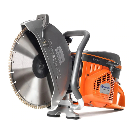
Husqvarna K970 III Workshop Manual
Hide thumbs
Also See for K970 III:
- Operator's manual (96 pages) ,
- Operator's manual (136 pages) ,
- Operator's manual (136 pages)
Table of Contents
Advertisement
Advertisement
Table of Contents

Related Manuals for Husqvarna K970 III


Summary of Contents for Husqvarna K970 III
- Page 1 Workshop manual K970 III English 1444 - 001 - 02.04.2020...
-
Page 2: Table Of Contents
Contents 1 Introduction 1.1 Document description..........3 1.2 Target group............3 1.3 Revisions..............3 1.4 Safety..............3 1.5 Servicing tools............3 2 Safety 2.1 Safety definitions............4 2.2 General safety instructions........4 2.3 Symbols on the product......... 4 3 Servicing data 3.1 Symbols in the diagrams........5 3.2 Tightening torques .......... -
Page 3: Introduction
1.5 Servicing tools The manual gives information about necessary servicing tools. Always use original tools from Husqvarna. 1444 - 001 - 02.04.2020 Introduction - 3... -
Page 4: Safety
2 Safety 2.1 Safety definitions Read the manual carefully and make sure you understand the instructions before Warnings, cautions and notes are used to point out using the product. specially important parts of the manual. WARNING: Used if there is a risk of injury or Always put on personal protective death for the operator or bystanders if the equipment:... -
Page 5: Servicing Data
3 Servicing data 3.1 Symbols in the diagrams Tightening torque, Nm 1444 - 001 - 02.04.2020 Servicing data - 5... -
Page 6: Tightening Torques
3.2 Tightening torques 3,0-4,0 3,0-4,0 17,0-23,0 2,0-3,0 9,0-11,0 10,0-12,0 9,0-11,0 9,0 -11,0 9,0-11,0 3,0-5,0 7,0-9,0 6 - Servicing data 1444 - 001 - 02.04.2020... - Page 7 5,0-7,0 5,0-7,0 5,0-7,0 10,0-18,0 14,0-16,0 16,0-18,0 11,0-13,0 1444 - 001 - 02.04.2020 Servicing data - 7...
- Page 8 25,0-30,0 38,0-42,0 8,0-10,0 5,0-7,0 4,0-5,0 4,0-10,0 8 - Servicing data 1444 - 001 - 02.04.2020...
- Page 9 7,0-10,0 25,0-30,0 35,0-40,0 12,0-14,0 7,0-10,0 6,0-8,0 20,0-25,0 7,0-9,0 14,0 2,0-3,0 3,0-4,0 2,0-3,0 14,0 2,0-3,0 17,0 1444 - 001 - 02.04.2020 Servicing data - 9...
-
Page 10: Servicing Tools
4 Servicing tools 4.1 Servicing tools overview Designation Used for Order No./Source tion Sealing plug To examine the crankcase for leaks. 503 55 22-01 Bearing press To assemble the primary bearing. 506 37 61-02 Press tool To disassemble and assemble the blade shaft bearings and axle. 575 96 20-01 Puller To disassemble the sealing rings of the crankcase in the crank- 504 91 40-01... -
Page 11: Servicing Tools Overview
4.2 Servicing tools overview Designation Used for Order No./Source tion Grip plate To divide the crankcase. 544 06 00-02 Bearing puller Remove the primary bearing from the crankshaft. 531 00 48-67 Bearing press To disassemble the primary bearing and assemble the crankshaft. 544 10 36-02 Combination wrench General. -
Page 12: Servicing Tools Overview
4.3 Servicing tools overview Designation Used for Order No./ Source tion Test spark plug To do servicing on the ignition unit. 502 71 13-01 Air clearance gauge To adjust the air clearance between the ignition module and the fly- 502 51 34-02 wheel. -
Page 13: Product Overview For Repair And Servicing
5 Product overview for repair and servicing 5.1 Product overview 1. Throttle control 14. Front belt guard 2. Air purge bulb 15. Lock screws for belt adjustment 3. Cylinder cover 16. Rear belt guard 4. Starter 17. Belt adjustment screw 5. -
Page 14: Basic Modules Of The Product
5.2 Basic modules of the product This chapter shows how to disassemble the product into basic modules. 5.2.1 To remove the starter 1. Remove the 4 screws on the guard. 2. Remove the starter. 14 - Product overview for repair 1444 - 001 - 02.04.2020 and servicing... - Page 15 5.2.2 To remove the cutting head 4. Remove the belt from the pulley and remove the cutting head. 1. Loosen the hose clip with a screwdriver. 2. Loosen the 3 nuts on the cutting head. Loosen the belt tension with the adjuster screw. 5.
- Page 16 the carburetor inlet. Removal of waste is best 5.2.4 To remove the cylinder cover done with a vacuum cleaner. To remove the air filter 1. Remove the air filter. Refer to on page 15 . 1. Remove the 4 screws and remove the air filter 2.
- Page 17 3. Remove the fuel hoses 6. Loosen the carburetor. 7. Remove the throttle cable. 4. Remove the 2 screws for the inlet hose and carburetor. 8. Remove the guide for the carburetor settings. 5. Remove screw for the inlet hose. 1444 - 001 - 02.04.2020 Product overview for repair and servicing - 17...
- Page 18 5.2.6 To remove the air duct 4. Remove the air duct. To remove the starter 1. Remove the starter. Refer to on page 14 . 2. Remove the cable lug for the stop switch cable. 5.2.7 To remove the muffler 1.
- Page 19 5.2.8 To remove and install the inlet manifold 5. Remove the 2 screws for the inlet manifold. To remove the 1. Remove the carburetor. Refer to carburetor on page 16 . 2. Remove the screw that hold the muffler to the crankcase.
- Page 20 8. Remove the inlet manifold. 5.2.9 To remove the inlet nozzle 1. Remove the screw for the inlet nozzle. 9. Install in the inlet manifold in the opposite sequence. 2. Remove the the inlet nozzle. Note: Make sure that the clamp is put fully together. 3.
- Page 21 8. Remove the 4 screws for the vibration damping units. 1444 - 001 - 02.04.2020 Product overview for repair and servicing - 21...
-
Page 22: Repair And Servicing
6 Repair and servicing 6.1 Starter 3. Remove the starter rope from the starter pulley. 6.1.1 To remove the starter rope 1. To remove the spring force from the return spring, pull out the starter rope approximately 12 in/30 cm. Hold the starter pulley with your thumb and put the starter rope in the notch on the starter pulley. - Page 23 6.1.2 To attach the new starter rope 6.1.3 To apply tension to the return spring 1. Put one end of the new starter rope from the top 1. Put the starter rope in the notch. through the hole in the starter pulley. Then pull it out 2.
- Page 24 6.1.4 To remove the starter pulley 6.1.5 To install the starter pulley 1. Decrease the tension in the return spring. Refer to Note: Make sure that the spacer sleeve does not fall off. To remove the starter rope on page 22 . 2.
- Page 25 6.1.6 To remove the spring assembly the flywheel rotates, the turning force pushes out the center pawls. WARNING: Always use protective glasses when you disassemble the spring unit. Risk for eye injuries, especially if a spring is broken. 1. Remove the 2 screws on the spring assembly. 2.
-
Page 26: Ignition System
6.1.11 To assemble the starter pawls 6.1.12 To install the starter The starter pawls must come into the correct position CAUTION: The spring must not get caught against the starter pulley sleeve. between the starter pawl and the flywheel. 1. Pull out the rope approximately 0.5 m. 1. - Page 27 transformer. The secondary coil increases the voltage to 6.2.4 To examine the ignition spark 20 000V. This causes a spark. 1. Ground the spark plug to the cylinder. 2. Move the stop switch to the operation position. 3. Pull the starter rope handle. If there is no spark, the problem can be a defective spark plug, defective ignition cable or a damaged short circuit cable.
- Page 28 6.2.6 To examine the ignition cable .02 in. 1. Pull up the rubber seal by the ignition unit and remove the ignition cable. 0.5 mm 1. Replace the spark plug with the test spark plug. Servicing tools overview on page 12 . Refer to 2.
- Page 29 6.2.7 To examine the short circuit cable and the 6.2.8 To remove the stop switch stop switch 1. Remove the screw and the cable. To remove the starter 1. Remove the starter. Refer to on page 14 . 2. Remove the short circuit cable on the ignition unit. 3.
-
Page 30: Flywheel
Tighten the screws with a torque of 10–12 6.3 Flywheel 6.3.1 To remove the flywheel Servicing Use a Husqvarna flywheel puller. Refer to tools overview on page 12 . To remove the starter 1. Remove the starter, refer to on page 14 . - Page 31 4. Put a 13 mm socket on the center screw of the 7. Attach the screw press in the center. flywheel. 8. Lock the outer socket with a wrench and tighten the 5. Attach the flywheel puller on the socket with the center screw until the flywheel releases.
-
Page 32: Air Filter
6.3.3 To install the flywheel 6.4.2 To replace the air filter The crankshaft and the center of the flywheel must be The air filter cannot be cleaned. When the power starts free from grease. Tightening torque 18 – 22 lbf·ft / 25 – to decrease, replace the air filter. -
Page 33: Fuel System
If the pressure is constant, the fuel system has no leakage. If the pressure drops, go to the next step. 2. Catch the fuel hose with a Husqvarna fuel filter hook (A). 3. To make sure that the fuel hose does not cause the leakage, remove the carburetor unit. - Page 34 6.5.4 To remove the fuel hose 3. Attach the weight and the fuel filter. 1. Remove the fuel hose from the carburetor. Refer to To remove the carburetor on page 16 . 2. Pull out the fuel hose from the fuel tank. 6.5.6 Function of the tank venting The fuel tank has a check valve that lets air enter the tank, but prevents fuel from leakage.
- Page 35 6.5.8 To remove the filter for the fuel tank venting If the air purge bulb does not fill with fuel when you push it, do this procedure. • Remove the check valve and then the filter for the fuel tank venting with a pair of pliers. 1.
- Page 36 6.5.11 To remove the air purge bulb 1. Remove the return hose and carburetor hose from the air purge bulb. 2. Push the snap lock with pliers and push the air purge bulb out. 36 - Repair and servicing 1444 - 001 - 02.04.2020...
-
Page 37: Carburetor
6.6 Carburetor 6.6.1 Carburetor components 1. Lever for the start throttle 14. Needle valve 2. Connection to the air purge bulb 15. Pump diaphragm measurement chamber 3. Fuel line from the fuel tank 16. Fuel pump valves 4. Impulse channel, from the crankcase to the 17. - Page 38 connection as short as possible, this gives a more If the needle valve does not open at 36 psi/2.5 bar, the accurate test result. needle valve has locked. Blow through the hole for filter compensation (A) to open the needle valve. 6.6.3 Needle valve 6.6.3.1 Indications of a needle valve leak There are many symptoms of a needle valve with a leak.
- Page 39 To examine and clean the the needle valve. Refer to 6.6.3.6 To examine and clean the needle valve needle valve on page 39 . 1. Remove the needle valve. 6.6.3.5 To examine external leakage and the function of the needle valve 2.
- Page 40 6.6.4 Pump unit function measurement chamber diaphragm. The diaphragm controls and keeps a constant level of fuel in the fuel The pump diaphragm (A) receives power by changes of chamber through the mechanically connected needle pressure in the crankcase. The pressure changes are valve.
- Page 41 6.6.8 To examine the fuel strainer 3. Clean the channels with compressed air. The rings in the illustration below show where to blow clean. 1. Examine the fuel strainer with a magnifying glass. 2. Remove loose dirt particles from the needle valve seating with air.
-
Page 42: Decompression Valve
6.6.11 High and low speed jets 3. Adjust the idle screw to an idle speed of approximately 2700 rpm. The low and high speed nozzles on the carburetor are set in the factory. They must not be adjusted. If the cutting blade rotates at this speed, do a check of the clutch. -
Page 43: Cylinder And Piston
6.7.2 To remove the decompression valve 6.7.4 To install the decompression valve • Remove the decompression valve with a long socket 1. Clean and examine the sealing washer. or the combination wrench. 2. Install the decompression valve. 6.7.3 To examine the decompression valve 1. - Page 44 6.8.2 To remove the cylinder contains piston ring compressors, a piston stop, and a support plate for the piston. 1. Remove the 8 screws for the cylinder, inlet manifold, muffler and remove the cylinder. 1. Put the support plate below the piston. 2.
- Page 45 4. Push out the wrist pin by hand. If it is tight, use a hours must be examined carefully. It is important to small hammer and light force. identify the cause of the unusual wear. 6.8.5 To examine cylinder wear 5.
-
Page 46: Piston Wear
6.9 Piston wear 6.8.7 Piston wear tolerances The cause of engine failure can be hard to find if the 6.8.7.1 Piston ring play previous operation and service of the product is not If the piston ring play is more than 0.006 in./0.15 mm, available. -
Page 47: To Assemble The Piston
6.10 To assemble the piston Examine the product to see if it has broken down because of an incorrect oil mixture, or no oil at all. If Lubricate new or cleaned bearings and piston rings with there is oil on a piston that is too hot it can carbonize. If 2-stroke oil before you assemble them. -
Page 48: To Assemble The Cylinder
6.11 To assemble the cylinder 3. Install a snap ring in the piston. 1. Clean and remove remaining bits of the first gasket from the surfaces that connect with the gasket. 2. Put the gasket on the cylinder. 4. Hold the piston in position, push in the wrist pin and install the other snap ring. -
Page 49: Crankcase
5. Push down the cylinder on the piston and let the 6.12.1 To examine the crankcase for leaks piston ring compressor move along the piston. 1. Turn the crankshaft until the exhaust port is fully Tighten the screws crosswise to a torque of 10–11 open. - Page 50 5. At the inlet port, attach the cylinder seal and connect 6.12.2 To remove the crankcase seal the pressure tester. To replace the crankcase seal rings, use a Husqvarna Servicing tools puller and an assembly punch. Refer to overview on page 10 .
- Page 51 6.12.5 To disassemble the crankcase Divide the crankcase with a universal puller and a grip Servicing tools overview plate from Husqvarna. Refer to on page 10 and Servicing tools overview on page 11 . 1. Disassemble the basic modules from the crankcase.
- Page 52 Servicing 4. Do the same with the other side of the crankcase. use 2 Husqvarna bearing press kits, refer to tools overview on page 10 . 1. Put the puller plate behind the bearing. 5. Make sure there is no radial play on the connecting rod by the crankshaft journal.
- Page 53 6.12.8 To assemble the crankcase Servicing tools Use a Husqvarna bearing press, refer to overview on page 11 . 1. Lock the crankcase half. The bottom of the cylinder plane must be down. This makes sure that the connecting rod does not push on the crankcase when you assemble the crankcase.
- Page 54 3. Put the sleeve from the tool kit against the d) Put in the 7 screws before the crankcase halves crankcase half. Use the mandrel with M12V threads. are put together. This helps put the gasket into Tighten it on the crankshaft by hand. position.
-
Page 55: Clutch
6.13.1 To remove the clutch To remove the clutch, use a Husqvarna piston stop, Servicing tools overview on page 10 . refer to 1. Lock the crankshaft with the piston stop. - Page 56 clutch. If it is necessary, replace with a full clutch 3. Remove the spring with a small screwdriver or a pin assembly. punch. 2. Measure the inner diameter of the clutch drum. 6.13.5 To examine the clutch shoes and hub CAUTION: Do not lubricate the clutch.
- Page 57 6.13.7 Belt pulley bearings 3. Put the hex key in a vise. Put the head of the screw on the hex key. Put the socket and cover in position. The clutch drum and the belt pulley are connected units. Install the washer and the nut. The belt pulley has 2 permanently lubricated ball bearings that are adjacent to each other without spacers.
-
Page 58: Cutting Head
6.14 Cutting head 6.13.9 To install the belt pulley bearings 1. Put the support plate of the bearings in a vise. Put 6.14.1 To disassemble the blade guard and the the 2 ball bearings on the support plate. bearing housing 1. - Page 59 4. Remove the pulley. speed, the brake shoes are pushed out from the brake drum. The retarder does not operate. 5. Remove the 4 screws, seals and the screen rings. 6.14.3 To disassemble the friction retarder 1. Remove the 4 screws. 2.
- Page 60 6.14.5 To assemble the retarder unit 6.14.6 To assemble the retarder and belt pulley 1. Put the spring (A) in position in the guide plate (B). 1. Assemble the plate of the retarder unit and the belt Note where the spring ends must be. pulley with the 4 screws.
- Page 61 • If you replace the bearings with a bearing press kit, housing. use the Husqvarna bearing press kit. Refer to Servicing tools overview on page 10 . 1. Turn the support for assemble with its shoulder up and put the bearing housing on top of it.
- Page 62 CAUTION: Do not put force between the inner and outer rings of the blade shaft bearing. The bearings can become damaged. Use a hydraulic press or a Husqvarna bearing press kit Servicing to assemble the blade shaft bearings. Refer to tools overview on page 10 .
-
Page 63: Wet System
5. Use the assembly support to make the bearing 6.15.2 To disassemble the wet system housing level. 1. Remove the screws that hold the spray nozzle. 6. Put the axle with the blade shaft bearing in the bearing housing with the spacer down. 7. -
Page 64: Throttle Trigger And Throttle Trigger Lockout
6.15.3 To assemble the wet system throttle trigger lockout before you apply the pliers to prevent damage to the surface. 1. Put the spray nozzles on to the blade guard. 2. To put the filter in the connector, push it in on a flat surface. - Page 65 3. Lift the lower part of the throttle trigger lockout and 6. Push out the spindle to the right side. Use a rod with pull it out from the pin. a diameter of 0.08–1.0 in./2–2.5 mm and approximately 4 in./10 mm in length and remove the throttle control wheel.
- Page 66 6.16.3 To install the throttle trigger and throttle 4. Install the right handle side. trigger lockout The spindles for the throttle trigger and the throttle control wheel must be installed from the right side. 1. Install the throttle trigger from the carburetor area (A).
-
Page 67: Troubleshooting
7 Troubleshooting 7.1 Engine does not start Remove the spark plug from the cylinder. Hold the cylinder, pull the starter rope and see if there are sparks between the spark plug electrodes. There are no sparks at the spark plug. Examine Cause Solution... -
Page 68: Engine Stops During Operation - No Sparks
7.2 Engine stops during operation - no sparks There are no sparks at the spark plug Problem Cause Solution Engine suddenly The switch is accidentally set to off. Set the switch to the left position. stops. The plug cap is not attached. Attach the plug cap fully. -
Page 69: Weak Output Or Change Of Speed
7.4 Weak output or change of speed There are no sparks at the spark plug Symptom/Category Cause Solution Compression is good Air has gone through the fuel pipe joint. Make sure it is tight. and there is no flame Air has gone into the fuel pipe because of a Replace. - Page 70 70 - Troubleshooting 1444 - 001 - 02.04.2020...
- Page 71 1444 - 001 - 02.04.2020 Troubleshooting - 71...
- Page 72 114237527 2020-04-02...