Nokia Alcatel-Lucent OmniSwitch 6360 Hardware User's Manual
Hide thumbs
Also See for Alcatel-Lucent OmniSwitch 6360:
- User manual (174 pages) ,
- Manual del usuario (173 pages) ,
- User manual (170 pages)

Related Manuals for Nokia Alcatel-Lucent OmniSwitch 6360


Summary of Contents for Nokia Alcatel-Lucent OmniSwitch 6360
- Page 1 Part No. 060711-00, Rev. A April 2020 OmniSwitch 6360 Hardware Users Guide www.al-enterprise.com...
- Page 2 This user guide documents OmniSwitch 6360 hardware, including chassis and associated components. The specifications described in this guide are subject to change without notice. The Alcatel-Lucent name and logo are trademarks of Nokia used under license by ALE. To view other trademarks used by affiliated companies of ALE Holding, visit: www.al-enterprise.com/en/legal/ trademarks-copyright.
-
Page 3: Table Of Contents
Contents About This Guide ......................vii Supported Platforms ......................vii Who Should Read this Manual? ..................vii When Should I Read this Manual? ................... vii What is in this Manual? ....................viii What is Not in this Manual? ....................viii How is the Information Organized? ................viii Documentation Roadmap .................... - Page 4 Contents Changing the Login Password ..................2-8 Setting the System Time Zone .................2-9 Setting the Date and Time ..................2-9 Setting Optional Parameters ..................2-9 Specifying an Administrative Contact ...............2-9 Specifying a System Name ................2-9 Specifying the Switch’s Location ..............2-9 Viewing Your Changes ..................2-10 Saving Your Changes .....................2-10 Chapter 3 Chassis and Power Supplies...
- Page 5 Contents Airflow Recommendations ..................3-22 Blank Cover Panels ....................3-23 Installing Blank Cover Panels .................3-23 Rack-Mounting ......................3-24 Installing Rack Mount Flanges ................3-24 Installing the Chassis In the Rack ................3-26 Standalone (Non-Rack Mounted) Installations ............3-27 Rack-Mounting 1/2 Width Switches ................3-28 Available 1/2 Width Rack-Mounting Kits .............3-28 General Rack-Mounting Guidelines ...............3-28 Installing Available Rack Mounting Kits ..............3-29 Installing the OS6360-RM-L Rack Mount Kit ............3-29...
- Page 6 Contents Appendix A Regulatory Compliance and Safety Information Declaration of Conformity: CE Mark ................A-1 Waste Electrical and Electronic Equipment (WEEE) Statement ........A-1 China RoHS: Hazardous Substance Table ..............A-2 Taiwan RoHS: Hazardous Substance Table ..............A-3 California Proposition 65 Warning ................A-4 Standards Compliance ....................
-
Page 7: About This Guide
About This Guide This OmniSwitch 6360 Hardware Users Guide describes OmniSwitch 6360 switch components and basic switch hardware procedures. Supported Platforms The information in this guide applies only to OmniSwitch 6360 switches. Who Should Read this Manual? The audience for this users guide is network administrators and IT support personnel who need to configure, maintain, and monitor switches and routers in a live network. -
Page 8: What Is In This Manual
What is in this Manual? This users guide includes the following hardware-related information: Descriptions of “Availability” features. • Technical specifications for the chassis, power supplies and modules. • Power supply requirements. • The dynamics of chassis airflow, including detailed illustrations of proper and improper airflow •... -
Page 9: Documentation Roadmap
Documentation Roadmap The OmniSwitch user documentation suite was designed to supply you with information at several critical junctures of the configuration process.The following section outlines a roadmap of the manuals that will help you at each stage of the configuration process. Under each stage, we point you to the manual or manuals that will be most helpful to you. - Page 10 Anytime The OmniSwitch CLI Reference Guide contains comprehensive information on all CLI commands supported by the switch. This guide includes syntax, default, usage, example, related CLI command, and CLI-to-MIB variable mapping information for all CLI commands supported by the switch. This guide can be consulted anytime during the configuration process to find detailed and specific information on each CLI command.
-
Page 11: Related Documentation
Related Documentation The following are the titles and descriptions of all the user manuals: OmniSwitch 6360 Hardware Users Guide • Complete technical specifications and procedures for all OmniSwitch 6360 chassis, power supplies, fans, and Network Interface (NI) modules. CLI Reference Guide •... -
Page 12: Technical Support
Technical Support A service agreement brings your company the assurance of 7x24 no-excuses technical support. You’ll also receive regular software updates to maintain and maximize your product’s features and functionality and on-site hardware replacement through our global network of highly qualified service delivery partners. With 24-hour access to the Service and Support web page, you’ll be able to view and update any case (open or closed) that you have reported to technical support, open a new case or access helpful release notes, technical bulletins, and manuals. -
Page 13: Chapter 1 Omniswitch 6360
1 OmniSwitch 6360 Refer to the information below for OmniSwitch 6360 models and components. Model Number Description OS6360-10 Fixed-configuration chassis in a 1U form factor with: 10 x RJ45 non-PoE ports • 2 x SFP ports • Internal power supply •... - Page 14 OmniSwitch 6360 Model Number Description OS6360-P24X Fixed-configuration chassis in a 1U form factor with: 24 x RJ45 PoE (802.3at) ports: • 2 x RJ45/SFP+ combo ports • 2 x SFP+ software configurable ports: • a) 2 x SFP uplinks b) 2 x SFP+ uplink or VFL ports Internal power supply •...
-
Page 15: Omniswitch 6360 Availability Features
OmniSwitch 6360 OmniSwitch 6360 Availability Features OmniSwitch 6360 Availability Features The switch provides a broad variety of availability features. Availability features are hardware and software-based safeguards that help prevent the loss of data flow in the unlikely event of a subsystem failure. - Page 16 OmniSwitch 6360 Availability Features OmniSwitch 6360 page 1-4 OmniSwitch 6360 Hardware Users Guide April 2021...
-
Page 17: Chapter 2 Getting Started
2 Getting Started Installing the Hardware Note. For information on configuring a Virtual Chassis (VC), refer to the Switch Management Guide. Items Required Grounding wrist strap • Phillips screwdriver • Flat-blade screwdriver • Site Preparation Environmental Requirements The switches have the following environmental and airflow requirements: The installation site must maintain a supported temperature and humidity range as given in the •... -
Page 18: Unpacking And Installing The Switch
Installing the Hardware Getting Started Earth grounding of all devices is fundamental to ensure long term reliability. All electrical equipment must be installed by a qualified, licensed electrician. • Every power supply that is connected to building power should be earth grounded. •... -
Page 19: Weight Considerations
Getting Started Installing the Hardware Blank cover panel • Rack mount brackets • Country-specific power cord(s) • Rubber table-mounting feet • Attachment screws • Assorted instructional cards, anti-static bags and additional packaging • Weight Considerations Weights vary depending on model type. Please refer to the chassis specifications table. OmniSwitch 6360 Hardware Users Guide April 2021 page 2-3... -
Page 20: Airflow Considerations
Mounting the Switch Getting Started Airflow Considerations To ensure proper airflow, be sure that your switch is placed in a clean, well-ventilated area free of dust and debris and provide minimum recommended clearance at the front, back and sides of the switch. Never obstruct chassis air vents. -
Page 21: Connections And Cabling
Getting Started Connections and Cabling Connections and Cabling Once your switch is properly installed, you should connect all network and management cables required for your network applications. Connections may include: Console connector • Cables to NIs or transceivers • Network Cable Installation Warning Never install exposed network cables outdoors. -
Page 22: Booting The Switch
Booting the Switch Getting Started Booting the Switch Now that you have installed the switch components and connected network and management cables, you can boot the switch. To boot the switch, plug all power supply cords into easily-accessible, properly grounded power outlets. -
Page 23: Your First Login Session
Getting Started Your First Login Session Your First Login Session In order to complete the setup process for the switch, you must complete the following steps during your first login session: Log in to the switch • Unlock session types •... -
Page 24: Unlocking Session Types
Your First Login Session Getting Started Unlocking Session Types Security is a key feature on an OmniSwitch switch. As described on page 2-7, when you access the switch for the first time, you must use a direct console port connection. All other session types (Telnet, FTP, WebView, and SNMP) are locked out until they are manually unlocked by the user. -
Page 25: Setting The System Time Zone
Getting Started Your First Login Session New password settings are automatically saved in real time to the local user database; the user is not required to enter an additional command in order to save the password information. Also note that new password information is retained following a reboot. -
Page 26: Viewing Your Changes
Your First Login Session Getting Started Viewing Your Changes To view your current changes, enter show system at the CLI prompt. Saving Your Changes Once you have configured this basic switch information, save your changes by entering write memory at the CLI command prompt. -
Page 27: Chassis And Power Supplies
3 Chassis and Power Supplies This chapter includes detailed information on the chassis types. Topics include: Chassis details and technical specifications: • OS6360-10, page 3-2. OS6360-P10, page 3-4. OS6360-24, page 3-6. OS6360-P24, page 3-8. OS6360-P24X, page 3-10. OS6360-PH24, page 3-12. OS6360-48, page 3-14 OS6360-P48,... -
Page 28: Omniswitch 6360 Chassis Details
OmniSwitch 6360 Chassis Details Chassis and Power Supplies OmniSwitch 6360 Chassis Details OS6360-10 OS6360-10 Front Panel Console / USB Item Description Status LEDs Console and USB port (1-8) 10/100/1000 Base-T ports (9-10) 10/100/1000 Base-T ports (11-12) SFP ports (1G) CLASS 1 M LASER CAUTION. CAUTION - CLASS 1 M LASER RADIATION WHEN OPEN. DO NOT VIEW DIRECTLY WITH OPTICAL INSTRUMENTS OS6360-10 Rear Panel Item... -
Page 29: Os6360-10 Chassis Specifications
Chassis and Power Supplies OmniSwitch 6360 Chassis Details OS6360-10 Chassis Specifications Chassis Height 4.4 cm (1.7 in) Chassis Width 21.7 cm (8.5 in) Chassis Depth 28.1 cm (11.1 in) Chassis Weight 1.8 kg (4.0 lb) Power Consumption (idle) 13 W Nominal Voltage 100V-240V, 50-60Hz Operating Temperature (Tmra) -
Page 30: Os6360-P10
OmniSwitch 6360 Chassis Details Chassis and Power Supplies OS6360-P10 OS6360-P10 Front Panel Console / USB Item Description Status LEDs Console and USB port (1-8) 10/100/1000 Base-T PoE(802.3at) ports (9-10) 10/100/1000 Base-T ports (11-12) SFP ports (1G) CLASS 1 M LASER CAUTION. CAUTION - CLASS 1 M LASER RADIATION WHEN OPEN. DO NOT VIEW DIRECTLY WITH OPTICAL INSTRUMENTS OS6360-P10 Rear Panel Item... -
Page 31: Os6360-P10 Chassis Specifications
Chassis and Power Supplies OmniSwitch 6360 Chassis Details OS6360-P10 Chassis Specifications Chassis Height 4.4 cm (1.7 in) Chassis Width 21.7 cm (8.5 in) Chassis Depth 28.1 cm (11.1 in) Chassis Weight 2.1 kg (4.6 lb) Power Consumption (idle) 13 W Nominal Voltage 100V-240V, 50-60Hz PoE Budget... -
Page 32: Os6360-24 Front Panel
OmniSwitch 6360 Chassis Details Chassis and Power Supplies OS6360-24 OS6360-24 Front Panel Item Description Status LEDs Console and USB port (1-24) 10/100/1000 Base-T ports (25-26) RJ-45 (10/100/1000) / SFP (1G) combo ports (27-28) SFP+ (1G/10G) Uplink or VFL ports CLASS 1 M LASER CAUTION. CAUTION - CLASS 1 M LASER RADIATION WHEN OPEN. DO NOT VIEW DIRECTLY WITH OPTICAL INSTRUMENTS OS6360-24 Rear Panel Item... -
Page 33: Os6360-24 Chassis Specifications
Chassis and Power Supplies OmniSwitch 6360 Chassis Details OS6360-24 Chassis Specifications Chassis Height 4.4 cm (1.7 in) Chassis Width 44 cm (17.3 in) Chassis Depth 22 cm (8.7 in) Chassis Weight 3.1 kg (6.8 lb) Power Consumption (idle) 21 W Nominal Voltage 100V-240V, 50-60Hz Operating Temperature (Tmra) -
Page 34: Os6360-P24
OmniSwitch 6360 Chassis Details Chassis and Power Supplies OS6360-P24 OS6360-P24 Front Panel Item Description Status LEDs Console and USB port (1-24) 10/100/1000 Base-T PoE (802.3at) ports (25-26) RJ-45 (10/100/1000) / SFP (1G) combo ports (27-28) SFP+ (1G/10G) Uplink or VFL ports CLASS 1 M LASER CAUTION. -
Page 35: Os6360-P24 Chassis Specifications
Chassis and Power Supplies OmniSwitch 6360 Chassis Details OS6360-P24 Chassis Specifications Chassis Height 4.4 cm (1.7 in) Chassis Width 44 cm (17.3 in) Chassis Depth 22 cm (8.7 in) Chassis Weight 3.2 kg (7.1 lb) Power Consumption (idle) 21 W Nominal Voltage 100V-240V, 50-60Hz PoE Budget... -
Page 36: Os6360-P24X
OmniSwitch 6360 Chassis Details Chassis and Power Supplies OS6360-P24X OS6360-P24X Front Panel Console / USB Item Description Status LEDs Console and USB port (1-24) 10/100/1000 Base-T PoE (802.3at) ports (25-26) RJ-45 (10/100/1000/10G) / SFP+ (1G/10G) combo ports (27-28) SFP+ (1G/10G) Uplink or VFL ports CLASS 1 M LASER CAUTION. -
Page 37: Os6360-P24X Chassis Specifications
Chassis and Power Supplies OmniSwitch 6360 Chassis Details OS6360-P24X Chassis Specifications Chassis Height 4.4 cm (1.7 in) Chassis Width 44 cm (17.3 in) Chassis Depth 30 cm (11.8 in) Chassis Weight 3.9 kg (8.6 lb) Power Consumption (idle) 34 W Nominal Voltage 100V-240V, 50-60Hz PoE Budget... -
Page 38: Os6360-Ph24
OmniSwitch 6360 Chassis Details Chassis and Power Supplies OS6360-PH24 OS6360-PH24 Front Panel Console / USB Item Description Status LEDs Console and USB port (1-24) 10/100/1000 Base-T PoE (802.3at) ports (25-26) RJ-45 (10/100/1000/10G) / SFP+ (1G/10G) combo ports (Upgradeable to 10G) (27-28) SFP+ (1G/10G) Uplink or VFL ports CLASS 1 M LASER CAUTION CAUTION - CLASS 1 M LASER RADIATION WHEN OPEN. -
Page 39: Os6360-Ph24 Chassis Specifications
Chassis and Power Supplies OmniSwitch 6360 Chassis Details OS6360-PH24 Chassis Specifications Chassis Height 4.4 cm (1.7 in) Chassis Width 44 cm (17.3 in) Chassis Depth 30 cm (11.8 in) Chassis Weight 3.9 kg (8.6 lb) Power Consumption (idle) 34 W Nominal Voltage 100V-240V, 50-60Hz PoE Budget... -
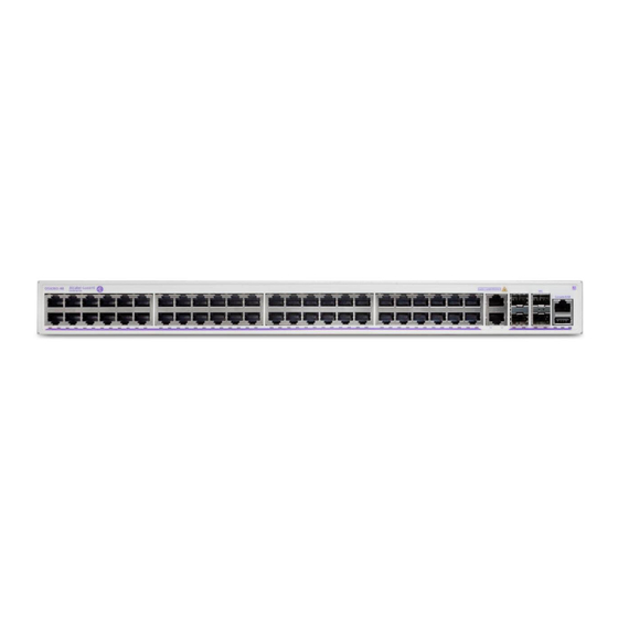
Page 40: Os6360-48 Front Panel
OmniSwitch 6360 Chassis Details Chassis and Power Supplies OS6360-48 OS6360-48 Front Panel Item Description Status LEDs Console and USB port (1-48) 10/100/1000 Base-T ports (49-50) RJ-45 (10/100/1000) / SFP (1G) combo ports (51-52) SFP+ (1G/10G) Uplink or VFL ports CLASS 1 M LASER CAUTION. CAUTION - CLASS 1 M LASER RADIATION WHEN OPEN. DO NOT VIEW DIRECTLY WITH OPTICAL INSTRUMENTS OS6360-48 Rear Panel Item... -
Page 41: Os6360-48 Chassis Specifications
Chassis and Power Supplies OmniSwitch 6360 Chassis Details OS6360-48 Chassis Specifications Chassis Height 4.4 cm (1.7 in) Chassis Width 44 cm (17.3 in) Chassis Depth 33 cm (13.0 in) Chassis Weight 4.6 kg (10.1 lb) Power Consumption (idle) 46 W Nominal Voltage 100V-240V, 50-60Hz Operating Temperature (Tmra) -
Page 42: Os6360-P48
OmniSwitch 6360 Chassis Details Chassis and Power Supplies OS6360-P48 OS6360-P48 Front Panel Item Description Status LEDs Console and USB port (1-48) 10/100/1000 Base-T PoE (802.3at) ports (49-50) RJ-45 (10/100/1000) / SFP (1G) combo ports (51-52) SFP+ (1G/10G) Uplink or VFL ports CLASS 1 M LASER CAUTION. -
Page 43: Os6360-P48 Chassis Specifications
Chassis and Power Supplies OmniSwitch 6360 Chassis Details OS6360-P48 Chassis Specifications Chassis Height 4.4 cm (1.7 in) Chassis Width 44 cm (17.3 in) Chassis Depth 33 cm (13.0 in) Chassis Weight 4.6 kg (10.1 lb) Power Consumption (idle) 47 W Nominal Voltage 100V-240V, 50-60Hz PoE Budget... -
Page 44: Os6360-P48X
OmniSwitch 6360 Chassis Details Chassis and Power Supplies OS6360-P48X OS6360-P48X Front Panel Console / USB Item Description Status LEDs Console and USB port (1-46) 10/100/1000 Base-T PoE (802.3at) ports (47-48) 10/100/1000/2.5G PoE (802.3bt) ports (49-50) RJ-45 (10/100/1000/10G) / SFP+ (1G/10G) combo ports (51-52) SFP+ (1G/10G) Uplink or VFL ports CLASS 1 M LASER CAUTION. -
Page 45: Os6360-P48X Chassis Specifications
Chassis and Power Supplies OmniSwitch 6360 Chassis Details OS6360-P48X Chassis Specifications Chassis Height 4.4 cm (1.7 in) Chassis Width 44 cm (17.3 in) Chassis Depth 30 cm (11.8 in) Chassis Weight 4.4 kg (9.7 lb) Power Consumption (idle) 60 W Nominal Voltage 100V-240V, 50-60Hz PoE Budget... -
Page 46: Chassis Status Leds
OmniSwitch 6360 Chassis Details Chassis and Power Supplies Chassis Status LEDs The chassis provides a series of status LEDs located on the front panel. These LEDs offer basic status information for hardware operation and port link and activity status. State Description Solid Green System Diagnostics and AOS bootup OK. -
Page 47: Mounting The Switch
Chassis and Power Supplies Mounting the Switch Mounting the Switch General Mounting Recommendations Elevated Operating Ambient Temperature. If installed in a closed or multi-rack assembly, the operating ambient temperature of the rack environment may be greater than the room’s ambient temperature. -
Page 48: Airflow Recommendations
Mounting the Switch Chassis and Power Supplies Airflow Recommendations To ensure proper airflow, be sure that your switch is placed in a clean, well-ventilated area free of dust and debris and provide minimum recommended clearance at the front, back and sides of the switch, as shown below. -
Page 49: Blank Cover Panels
Chassis and Power Supplies Mounting the Switch Blank Cover Panels Blank cover panels are provided with your switch and are used to cover empty slots. These cover panels play an important role in chassis airflow and temperature management. If your switch is not fully populated and blank cover panels are not installed over empty slot locations, airflow is adversely affected. -
Page 50: Rack-Mounting
Rack-Mounting Chassis and Power Supplies Rack-Mounting Refer to the following important guidelines before installing the chassis in a rack: Two people are required to rack mount the switch: One person to lift the chassis into position and one • person to secure the chassis to the rack using the rack mount screws. The chassis has rack-mount flanges that support standard 19-inch rack mount installations. - Page 51 Chassis and Power Supplies Rack-Mounting Press the flange and spring clip until the flange clicks into place and the clip is in the in (engaged) position. Clip in “In” (engaged) position “CLICK” Secure the flange to the chassis using the attachment screw (provided). Repeat steps 1 through 4 for the flange on the opposite side of the chassis.
-
Page 52: Installing The Chassis In The Rack
Rack-Mounting Chassis and Power Supplies Installing the Chassis In the Rack Mark the holes on the rack where the chassis is to be installed. One person should lift and position the chassis until the rack-mount flanges are flush with the rack post. -
Page 53: Standalone (Non-Rack Mounted) Installations
Chassis and Power Supplies Rack-Mounting Standalone (Non-Rack Mounted) Installations The chassis can also be placed unmounted on a stable, flat surface as a standalone unit. Be sure that the surface can accommodate the full, populated weight of all switches being installed. (Approximate chassis weights are provided in the technical specifications tables in the “OmniSwitch 6360 Chassis Details”... -
Page 54: Rack-Mounting 1/2 Width Switches
Rack-Mounting 1/2 Width Switches Chassis and Power Supplies Rack-Mounting 1/2 Width Switches The following kits are available for rack mounting 1/2 width switches. Note. Some factory-installed screws may need to be removed prior to mounting, depending on the kit being used. Available 1/2 Width Rack-Mounting Kits Description OS6360-RM-19-L... -
Page 55: Installing Available Rack Mounting Kits
Chassis and Power Supplies Installing Available Rack Mounting Kits Installing Available Rack Mounting Kits Note. Some factory-installed screws may need to be removed prior to mounting, depending on the kit being used. Installing the OS6360-RM-L Rack Mount Kit A single chassis can also be mounted into a standard 19-inch rack using L-brackets, as shown in the figure below. -
Page 56: Grounding The Chassis
Grounding the Chassis Chassis and Power Supplies Grounding the Chassis The switch has a grounding lug located on the rear of the chassis. This lug uses 10-32 screws and is surrounded by a small paint-free area, which provides metal-to-metal contact for a ground connection. Use this connector to supplement the ground provided by the AC power cord. -
Page 57: Monitoring Chassis Components
Chassis and Power Supplies Monitoring Chassis Components Monitoring Chassis Components Viewing Chassis Slot Information To view basic slot information, enter the show module command at the CLI prompt: -> show module To view more detailed information, use the show module long command: ->... -
Page 58: Temperature Errors
Monitoring Chassis Temperature Chassis and Power Supplies Temperature Errors The switch monitors the chassis temperature at all times via an onboard sensor. If an over-temperature condition occurs, there are two different levels of error severity: Warning threshold has been exceeded •... -
Page 59: Managing Power Over Ethernet (Poe)
4 Managing Power over Ethernet (PoE) Power over Ethernet (PoE) provides inline power directly from the switch’s Ethernet ports. Powered Devices (PDs) such as IP phones, wireless LAN stations, Ethernet hubs, and other access points can be plugged directly into the Ethernet. From these RJ-45 the devices receive both electrical power and data flow. -
Page 60: In This Chapter
In This Chapter Managing Power over Ethernet (PoE) In This Chapter This chapter provides specifications and descriptions of hardware and software used to provide PoE for attached devices. The chapter also provides information on configuring PoE settings on the switch through the Command Line Interface (CLI). -
Page 61: Power Over Ethernet Specifications
Managing Power over Ethernet (PoE) Power over Ethernet Specifications Power over Ethernet Specifications The table below lists general specifications for Alcatel-Lucent’s Power over Ethernet support. For more detailed power supply and Power Source Equipment (PSE) specifications, refer to Chapter 3, “Chassis and Power Supplies.”... -
Page 62: Power Over Ethernet Budget
Power over Ethernet Budget Managing Power over Ethernet (PoE) Power over Ethernet Budget The following table lists the Power over Ethernet wattages available based on the number and types of power supplies installed. OmniSwitch PoE Budget 120W OS6360-P10 180W OS6360-P24 380W OS6360-P24X OS6360-PH24... -
Page 63: Viewing Poe Status
Managing Power over Ethernet (PoE) Power over Ethernet Budget Viewing PoE Status To view current PoE status and settings, use the show lanpower slot command: -> show lanpower slot 1/1 Port Maximum(mW) Actual Used(mW) Status Priority On/Off Class Type ----+-----------+---------------+-----------+---------+--------+-------+---------- 60000 Powered Off 60000... -
Page 64: Enabling 802.3Bt
Power over Ethernet Budget Managing Power over Ethernet (PoE) Although class-detection is disabled by default, the switch still provides power to incoming PDs (if avail- able in the power budget). However, to strictly enforce class detection it must be enabled using the lanpower slot class-detection command. -
Page 65: Configuring The Total Power Available To A Port
Managing Power over Ethernet (PoE) Power over Ethernet Budget Fast PoE requires the proper FPGA/CPLD version, refer to the release notes for additional information. • Factory default switches that don't have any PoE configuration must have an initial PoE configuration •... -
Page 66: Setting Port Priority Levels
Power over Ethernet Budget Managing Power over Ethernet (PoE) To increase or decrease the total power available to a slot, use the lanpower slot maxpower command. Since you are setting the power allowance for an individual slot, you must specify a chassis/slot value in the command line. -
Page 67: Understanding Guard Band
Managing Power over Ethernet (PoE) Understanding Guard Band Understanding Guard Band Guard Band functionality is implemented when the switch has to provide power to a newly connected PD. This functionality is more relevant on switches that have a lower amount of total PoE power available for the switch but a higher default maximum PoE power available to some ports. -
Page 68: Understanding Priority Disconnect
Understanding Priority Disconnect Managing Power over Ethernet (PoE) Understanding Priority Disconnect The priority disconnect function differs from the port priority function described on page 4-8 in that it applies only to the addition of powered devices (PDs) in tight power budget conditions. Priority discon- nect is used by the system software in determining whether an incoming PD will be granted or denied power when there are too few watts remaining in the PoE power budget for an additional device. -
Page 69: Priority Disconnect Is Enabled; Same Priority Level On All Pd
Managing Power over Ethernet (PoE) Understanding Priority Disconnect Priority Disconnect is Enabled; Same Priority Level on All PD Reminder. Priority disconnect examples are applicable only when there is inadequate power remaining to power an incoming device. When a PD is being connected to a port with the same priority level as all other in the slot, the physical port number is used to determine whether the incoming PD will be granted or denied power. -
Page 70: Priority Disconnect Is Disabled
Understanding Priority Disconnect Managing Power over Ethernet (PoE) Priority Disconnect is Disabled Reminder. Priority disconnect examples are applicable only when there is inadequate power remaining to power an incoming device. When priority disconnect is disabled, power will be denied to any incoming PD, regardless of its port priority status (i.e., low, high, and critical) or physical port number (i.e., 1–24). -
Page 71: Monitoring Power Over Ethernet Via Cli
Managing Power over Ethernet (PoE) Monitoring Power over Ethernet via CLI Monitoring Power over Ethernet via CLI To monitor current PoE statistics and settings, use the show lanpower slot command. The command output displays a list of all current PoE-capable, along with the following information for each port: Maximum power available to the port, in milliwatts •... - Page 72 Monitoring Power over Ethernet via CLI Managing Power over Ethernet (PoE) page 4-14 OmniSwitch 6360 Hardware Users Guide April 2021...
-
Page 73: Regulatory Compliance And Safety Information
A Regulatory Compliance and Safety Information This appendix provides information on regulatory agency compliance and safety for the OmniSwitch. Declaration of Conformity: CE Mark This equipment is in compliance with the essential requirements and other provisions of Directive 2014/30/EU (EMC), 2014/35/EU (LVD), 2011/65/EU (RoHS-Directive), 91/263/EEC (Telecom Terminal Equipment, if applicable), 2014/53/EU (R&TTE, if applicable). -
Page 74: China Rohs: Hazardous Substance Table
China RoHS: Hazardous Substance Table Regulatory Compliance and Safety Information China RoHS: Hazardous Substance Table page A-2 OmniSwitch 6360 Hardware Users Guide April 2021... -
Page 75: Taiwan Rohs: Hazardous Substance Table
Regulatory Compliance and Safety Information Taiwan RoHS: Hazardous Substance Table Taiwan RoHS: Hazardous Substance Table OmniSwitch 6360 Hardware Users Guide April 2021 page A-3... -
Page 76: California Proposition 65 Warning
California Proposition 65 Warning Regulatory Compliance and Safety Information California Proposition 65 Warning WARNING: This product can expose you to chemicals including Pb and Pb compounds, which is known to the State of California to cause cancer and birth defects or other reproductive harm. For more information go to www.P65Warnings.ca.gov. -
Page 77: Standards Compliance
Regulatory Compliance and Safety Information Standards Compliance Standards Compliance The product bears the CE mark. In addition it is in compliance with the following other safety and EMC standards. Note. All hardware switching modules used in an OmniSwitch switch comply with Class A standards. - Page 78 Standards Compliance Regulatory Compliance and Safety Information EMI/EMC Standards FCC Part 15:2012, Subpart B, Class A • ICES–003:2012 Issue 5, Class A • ANSI C63.4-2009 • FCC CRF Title 47 Subpart B (Class A) • VCCI (Class A) • AS/NZS 3548 (Class A) •...
-
Page 79: Fcc Class A, Part 15
Regulatory Compliance and Safety Information Standards Compliance FCC Class A, Part 15 This equipment has been tested and found to comply with the limits for Class A digital device pursuant to Part 15 of the FCC Rules.These limits are designed to provide reasonable protection against harmful interference when the equipment is operated in a commercial environment.This equipment generates, uses, and can radiate radio frequency energy and, if not installed and used in accordance with the instructions in this guide, may cause interference to radio communications.Operation of this equipment in a residential... -
Page 80: Korea Emissions Statement
Standards Compliance Regulatory Compliance and Safety Information Korea Emissions Statement A 급 기기 ( 업무용 방송통신 기자재 ) Class A Equipment (Business equipment) This equipment is registered for Electromagnetic 이 기기는 업무용 (A 급 ) 전자파적합기기로서 판 Conformity Registration as business equipment 매자... -
Page 81: Translated Safety Warnings
Regulatory Compliance and Safety Information Translated Safety Warnings Translated Safety Warnings Blank Panels Warning Because they regulate airflow and help protect internal chassis components, blank cover plates should remain installed at empty module slots and power supply bays at all times. Français: Les caches blancs remplissent trois fonctions importantes: ils évitent tout risque de choc électrique à... -
Page 82: Invisible Laser Radiation Warning
Translated Safety Warnings Regulatory Compliance and Safety Information Invisible Laser Radiation Warning Lasers emit invisible radiation from the aperture opening when no fiber-optic cable is connected. When removing cables do not stare into the open apertures. In addition, install protective aperture covers to fiber ports with no cable connected. -
Page 83: Proper Earthing Requirement Warning
Regulatory Compliance and Safety Information DC Power Supply Connection Warning Proper Earthing Requirement Warning To avoid shock hazard: The power cord must be connected to a properly wired and earth receptacle. • Any equipment to which this product will attached must also be connected to properly wired •... -
Page 84: Read Important Safety Information Warning
DC Power Supply Connection Warning Regulatory Compliance and Safety Information Read Important Safety Information Warning The Getting Started Guide that accompanied this equipment contains important safety information about which you should be aware when working with hardware components in this system. You should read this guide before installing, using, or servicing this equipment. -
Page 85: Instrucciones De Seguridad En Español
Regulatory Compliance and Safety Information Instrucciones de seguridad en español Instrucciones de seguridad en español Advertencia sobre el levantamiento del chasis Se requieren dos personas para levantar el chasis. Debido a su peso, la elevación del chasis sin ayuda puede causar daños corporales. También es seguro doblar sus rodillas y guardar su espalda derecho al ayudar a levantar el chasis. -
Page 86: Advertencia Sobre Una Apropiada Conexión A Tierra
Instrucciones de seguridad en español Regulatory Compliance and Safety Information Advertencia sobre una apropiada conexión a tierra Para evitar peligro de descargas: El cable de alimentación debe estar conectado a una toma de alimentación adecuadamente cableada • y con toma de tierra. Cualquier equipo al cual se conecte este producto debe estar también conectado a tomas de alimentación adecuadamente cableadas.