Table of Contents
Advertisement
Quick Links
Advertisement
Table of Contents

Related Manuals for Bosch LTC 4600 Series


Summary of Contents for Bosch LTC 4600 Series
- Page 1 LTC 4600 Series Instruction Manual Fiber Optic Transmission System...
-
Page 2: Important Safeguards
EN | 2 LTC 4600 Series | Instruction Manual | Important Safeguards Important Safeguards 1. Read, Follow, and Retain Instructions - All safety 10. Power Sources - Operate the unit only from the type and operating instructions should be read and of power source indicated on the label. - Page 3 EN | 3 LTC 4600 Series | Instruction Manual | Safety Precautions Safety Precautions For Indoor Product 1. Water and Moisture - Do not use this unit near water - for example, in a wet basement, in an unprotected outdoor installation, or in any area classified as a wet location.
-
Page 4: Fcc Information
EN | 4 LTC 4600 Series | Instruction Manual | FCC & ICES Information FCC & ICES INFORMATION Sicherheitshinweise (U.S.A. and Canadian Models Only) This device complies with part 15 of the FCC Rules. Operation is subject to the following two conditions:... - Page 5 EN | 5 LTC 4600 Series | Instruction Manual | Safety Precautions Medidas de Segurança Veiligheidsmaatregelen CUIDADO: PARA REDUZIR O RISCO DE CHOQUE VOORZICHTIG: OPEN DE BEHUIZING OF DE ACHTERKANT ELÉCTRICO, NÃO RETIRE A TAMPA (OU A PARTE VAN HET APPARAAT NIET. ZO VERMINDERT U HET RISICO POSTERIOR).
-
Page 6: Table Of Contents
LTC 4671 Series Modules for System4/Allegiant® Keyboard Transmission ....14 LTC 4651 Series Modules for Bosch Biphase Control Code or RS-232 Transmission ..15 LTC 4681, LTC 4682 Series Modules for Ethernet Data Transmission . -
Page 7: Unpacking
If any items are missing, notify your Bosch Security A list of available models is shown below. Complete Systems, Inc. Sales Representative or Customer specifications can be found on the LTC 4600 Series Service. Data Sheet that can be downloaded from www.boschsecuritysystems.com. -
Page 8: Installation
EN | 8 LTC 4600 Series | Instruction Manual | Installation 4.2 Installing Stand-alone Modules INSTALLATION 1. Choose an appropriate flat surface where the Installing Rack-mount Modules stand-alone module can be conveniently mounted, 1. Install the LTC 4637 Series card cage unit as then mark the locations of the keyhole slots on the described in a later section of this document. -
Page 9: 4.3 Ltc 4641, Ltc 4642 Series Modules For Video Transmission
EN | 9 LTC 4600 Series | Instruction Manual | Installation 4.3 LTC 4641, LTC 4642 Series Modules for Video Transmission 4.3.1 Indicators / Operation 1. The POWER LED illuminates when AC power is applied to the unit. 2. LTC 4642/60 and LTC 4642/50 units: The Video Out / AGC LED illuminates GREEN when a video signal is being received, or RED if a video signal is not present. -
Page 10: Ltc 4744, Ltc 4745 Series Modules For Simultaneous 4-Channel Video Transmission
EN | 10 LTC 4600 Series | Instruction Manual | Installation 3. LTC 4744/60, LTC 4744/50, and LTC 4744/00 4.4 LTC 4744, LTC 4745 Series Modules units: The respective CAMERA ON LED for Simultaneous 4-Channel Video illuminates when a video signal is connected to its Transmission input. -
Page 11: Ltc 4630, Ltc 4631 Series Modules For Bilinx
EN | 11 LTC 4600 Series | Instruction Manual | Installation 4.5.2 Indicators / Operation 4.5 LTC 4630, LTC 4631, Series Modules 1. The POWER LED illuminates when AC power for Bilinx Video/Data Transmissions is applied to the unit. 4.5.1 Important Considerations 2. -
Page 12: Ltc 4628, Ltc 4629 Series Modules For Video + Bosch Biphase Control Code Transmission
EN | 12 LTC 4600 Series | Instruction Manual | Installation 4.6 LTC 4628, LTC 4629 Series Modules for Video + Bosch Biphase Control Code Transmission 4.6.1 Indicators / Operation 1. The POWER LED illuminates when AC power is applied to the unit. - Page 13 EN | 13 LTC 4600 Series | Instruction Manual | Chapter Bosch Security Systems | 10 October 2003...
-
Page 14: Ltc 4671 Series Modules For System4/Allegiant® Keyboard Transmission
EN | 14 LTC 4600 Series | Instruction Manual | Installation A termination resistor is typically NOT required when LTC 4671 Series Modules for a module is connected to the following controller System4 / Allegiant Keyboard devices: Transmission • Allegiant LTC 8500 Series main CPU bays 1. -
Page 15: Ltc 4651 Series Modules For Bosch Biphase Control Code Or Rs-232 Transmission
EN | 15 LTC 4600 Series | Instruction Manual | Installation 4.8 LTC 4651 Series Modules for Bosch Biphase Control Code or RS-232 Transmission 4.8.1 Indicators / Operation 1. The POWER LED will light when AC power is applied to the unit. -
Page 16: Ltc 4681, Ltc 4682 Series Modules For Ethernet Data Transmission
EN | 16 LTC 4600 Series | Instruction Manual | Installation 4.9 LTC 4681, LTC 4682 Series Modules c) Dip Switch 3: DUPLEX – This setting applies for Ethernet Data Transmission only when AUTO NEGOTIATE is disabled. This setting forces the connection type to either... -
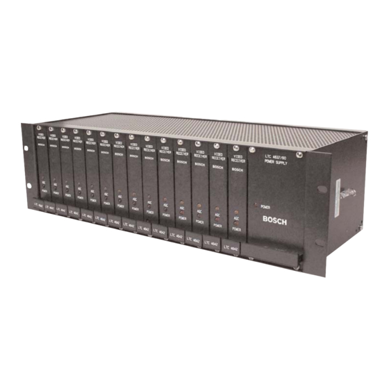
Page 17: Ltc 4637 Series Rack-Mount Card Cage
EN | 17 LTC 4600 Series | Instruction Manual | Replacement Parts 4.10.3 LTC 4637 Maintenance / Service 4.10 LTC 4637 Series Rack-mount Information Card Cage 1. The power supply is fused with a 1A slow blow 4.10.1 Installation fuse. To replace the fuse, remove the AC power line 1. -
Page 18: Troubleshooting
EN | 18 LTC 4600 Series | Instruction Manual | Troubleshooting TROUBLESHOOTING Video Links: Video Problems • Verify that a valid video signal is being applied to the transmitter module • Verify the integrity of the coax connections between devices and fiber modules •... -
Page 19: Dimensional Outlines
EN | 19 LTC 4600 Series | Instruction Manual | Dimensional Outlines DIMENSIONAL OUTLINES LTC 4641 VIDEO TX BOSCH +9-12VDC 25.4 1.19 Figure 13 Stand-alone Modules: LTC 4641/60, LTC 4641/50 BOSCH 3.06 Figure 14 Stand-alone Modules: LTC 4642/50, LTC 4642/60,... - Page 20 EN | 20 LTC 4600 Series | Instruction Manual | Dimensional Outlines BOSCH BOSCH 4.45 LTC 4xxx 1 LTC 4637 Figure 15 Stand-alone Modules: LTC 4744/50, Rack Width LTC 4744/60, LTC 4671/60, LTC 4671/50, Figure 17 Rack-mount Modules: LTC 4600/00,...
- Page 21 EN | 21 LTC 4600 Series | Instruction Manual | Bosch Security Systems | September 20, 2004...
- Page 22 EN | 22 LTC 4600 Series | Instruction Manual | Bosch Security Systems | September 20, 2004...
- Page 23 EN | 23 LTC 4600 Series | Instruction Manual | Bosch Security Systems | September 20, 2004...
- Page 24 The Netherlands Republic of Singapore Fax: 1-717-735-6560 Tele +31 40 27 80000 Tel: 65 (6) 319 3486 www.boschsecuritysystems.com © 2004 Bosch Security Systems GmbH 3935 890 22816 04-38 | Updated September 20 , 2004 | Data subject to change without notice.