
Related Manuals for Toro Pro Force 44554


Summary of Contents for Toro Pro Force 44554
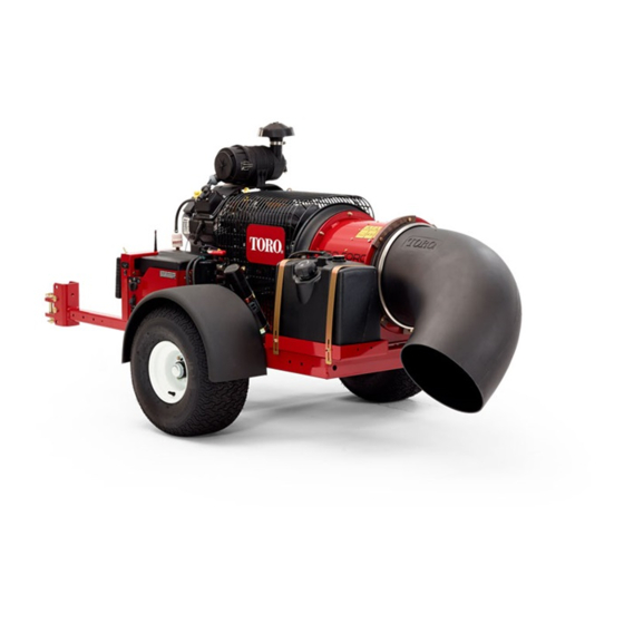
- Page 1 Form No. 3397-613 Rev A Pro Force ® Debris Blower Model No. 44554—Serial No. 315000001 and Up *3397-613* A Register at www.Toro.com. Original Instructions (EN)
- Page 2 This spark ignition system complies with Canadian ICES-002. © 2015—The Toro® Company Contact us at www.Toro.com. 8111 Lyndale Avenue South Printed in the USA...
-
Page 3: Table Of Contents
1 Connecting the Battery .......... 8 2 Mounting the Hitch to the Debris Blower ....9 You may contact Toro directly at www.Toro.com for product 3 Connecting the Debris Blower to the Tow and accessory information, help finding a dealer, or to register Vehicle ............... -
Page 4: Safety
Safe Handling of Fuels Safety • To avoid personal injury or property damage, use extreme care in handling gasoline. Gasoline is extremely Hazard control and accident prevention are dependent flammable and the vapors are explosive. upon the awareness, concern, and proper training of the personnel involved in the operation, transport, •... - Page 5 Use a damp cloth to keep units clean. Remove mud, • concrete, dirt, etc. after use to prevent obstructing or Use only Toro approved attachments. Warranty may be clogging the buttons, levers, wiring, and switches. voided if used with unapproved attachments.
- Page 6 Hauling • Use care when loading or unloading the machine into a trailer or truck. • Use full width ramps for loading machine into trailer or truck. • Tie the machine down securely using straps, chains, cable, or ropes. Both front and rear straps should be directed down and outward from the machine.
-
Page 7: Safety And Instructional Decals
Safety and Instructional Decals Safety decals and instructions are easily visible to the operator and are located near any area of potential danger. Replace any decal that is damaged or lost. 115-5105 1. Warning—read the Operator's Manual. 2. Warning—do not operate this machine unless you are trained. 3. -
Page 8: Setup
Setup Loose Parts Use the chart below to verify that all parts have been shipped. Procedure Description Qty. Petroleum jelly (not supplied) Connect the battery. Debris-blower assembly Hitch Bolt (3/8 x 3 inches) Flange nut (3/8 inch) Mount the hitch to the debris blower. Hitch clevis Bolt (5/8 x 4-1/2 inch) Locknut (5/8 inch) -
Page 9: Mounting The Hitch To The Debris Blower
2. Insert the hitch tube into the frame brackets (Figure DANGER Battery electrolyte contains sulfuric acid which is a deadly poison and causes severe burns. • Do not drink electrolyte and avoid contact with skin, eyes or clothing. Wear safety glasses to shield your eyes and rubber gloves to protect your hands. -
Page 10: Product Overview
Product Overview • Remove the bolts and nuts securing the hitch tube to frame brackets (Figure • Secure the tube to the frame with the bolts and Controls flange nuts. 4. Connect the blower clevis hitch to the tow-vehicle Nozzle-Direction Button hitch with the hitch pin and clevis (Figure Press the button to rotate the nozzle to the desired direction... - Page 11 automatically to the R position. To shut engine off, rotate the key counterclockwise to the O position (Figure Choke Control To start a cold engine, move the choke control lever (Figure 7) to the O position. G030332 Figure 7 1. Choke control 3.
-
Page 12: Operation
Operation DANGER In certain conditions, gasoline is extremely Note: Determine the left and right sides of the machine flammable and highly explosive. A fire or explosion from the normal operating position. from gasoline can burn you and others and can damage property. -
Page 13: Checking The Engine-Oil Level
Note: This space in the tank allows gasoline to WARNING expand. Do not fill the fuel tanks completely full. Gasoline is harmful or fatal if swallowed. Long-term 4. Install fuel tank cap securely. exposure to vapors can cause serious injury and illness. -
Page 14: Starting And Stopping The Engine
Starting and Stopping the Engine Starting the Engine WARNING Rotating parts can cause serious personal injury. • Keep hands and feet away from the machine when it is running. • Keep hands, feet, hair, and clothing away from all moving parts to prevent injury. •... -
Page 15: Adjusting The Nozzle Direction
Adjusting the Nozzle Direction WARNING Discharged air has considerable force and could Press the nozzle direction button to rotate the nozzle to the cause injury or loss of footing. desired direction (Figure 11). • Stay away from nozzle opening when machine is operating. -
Page 16: Maintenance
Maintenance Recommended Maintenance Schedule(s) Maintenance Service Maintenance Procedure Interval • Check the condition and the tension of the belt. After the first 8 hours • Check the torque of the wheel lug nuts. After the first 10 hours • Check the engine oil level. •... -
Page 17: Daily Maintenance Checklist
Daily Maintenance Checklist Duplicate this page for routine use. Maintenance Check Item For the week of: Mon. Tues. Wed. Thurs. Fri. Sat. Sun. Check the instrument operation Check the fuel level. Check the engine oil level. Clean the engine air cooling fins. -
Page 18: Servicing The Air Cleaner
Servicing the Air Cleaner 3. Install the new air filter; refer to Installing the Air Filter (page 18). Service Interval: Every 25 hours—Clean the air filter element for damage (more frequently if Installing the Air Filter conditions are dusty or sandy). Important: To prevent engine damage, always operate Every 100 hours—Replace the air filter element (more frequently if conditions are dusty or sandy). -
Page 19: Servicing The Carbon Canister
Servicing the Carbon Canister Replacing the Carbon-Canister Air Filter Service Interval: Every 200 hours 1. Stop the engine, remove the key, and wait for all moving parts to stop before leaving the operating position. 2. Remove and discard the carbon canister air filter (Figure 13). - Page 20 Checking the Engine Oil Level Note: A hose may be inserted onto the drain valve to direct the oil flow. The hose is not included with the Service Interval: Before each use or daily machine. Note: The best time to check the engine oil is when the 5.
-
Page 21: Servicing The Spark Plugs
Removing the Spark Plugs 3. Apply a thin coat of new oil to the rubber gasket on the replacement filter (Figure 18). 1. Stop the engine, remove the key, and wait for all moving 4. Install the replacement oil filter to the filter adapter, parts to stop before leaving the operating position. -
Page 22: Servicing The Fuel Tank
Cleaning the Engine Screen and the Oil Cooler Service Interval: Before each use or daily Before each use, check and clean the engine screen and oil cooler. Remove any build up of grass, dirt or other debris from the oil cooler and engine screen (Figure 22). -
Page 23: Adjusting The Belt
G017855 Figure 24 1. Nozzle guides Adjusting the Belt Service Interval: After the first 8 hours G015845 Every 50 hours Figure 25 If the belt slips when changing the direction of the nozzle, an 1. Mounting bolts 4. Torque wrench in pulley mounting bracket [22.6 adjustment to the belt is required. -
Page 24: Electrical Maintenance
Electrical Maintenance Important: Before welding on the machine, disconnect the controller and the negative cable from the battery to prevent damage to the electrical system. Fuses Engine A 15 amp in-line fuse is incorporated into the engine wiring harness (Figure 26). -
Page 25: Storage
Storage out of reach of children or other unauthorized users. Cover the machine to protect it and keep it clean. 1. Turn off the engine, remove the spark plug wire, and remove the key from the ignition. Waste Disposal 2. Remove grass clippings, dirt, and grime from the external parts of the entire machine, especially the Engine oil, engine and remote control batteries are pollutants engine. - Page 26 Notes:...
- Page 27 The Way Toro Uses Information Toro may use your personal information to process warranty claims, to contact you in the event of a product recall and for any other purpose which we tell you about. Toro may share your information with Toro's affiliates, dealers or other business partners in connection with any of these activities. We will not sell your personal information to any other company.
- Page 28 Countries Other than the United States or Canada Customers who have purchased Toro products exported from the United States or Canada should contact their Toro Distributor (Dealer) to obtain guarantee policies for your country, province, or state. If for any reason you are dissatisfied with your Distributor's service or have difficulty obtaining guarantee information, contact the Toro importer.