Table of Contents
Advertisement
Quick Links
Advertisement
Chapters
Table of Contents

Related Manuals for Asus Z11PA-U12 series


Summary of Contents for Asus Z11PA-U12 series
- Page 1 Z11PA-U12 Series User Guide...
- Page 2 Product warranty or service will not be extended if: (1) the product is repaired, modified or altered, unless such repair, modification of alteration is authorized in writing by ASUS; or (2) the serial number of the product is defaced or missing.
-
Page 3: Table Of Contents
Operation safety ....................x Australia statement notice ................xi How this guide is organized ................xii Where to find more information ..............xii Z11PA-U12 Series specifications summary............xiv Chapter 1: Product Introduction Welcome! ....................1-2 Package contents ..................1-2 Serial number label ..................1-3 Special features.................. - Page 4 3.2.2 Using the dual function power switch .......... 3-3 Chapter 4: BIOS Setup Managing and updating your BIOS ............4-2 4.1.1 ASUS CrashFree BIOS 3 utility........... 4-2 4.1.2 ASUS EzFlash Utility..............4-3 4.1.3 BUPDATER utility ............... 4-4 BIOS setup program .................. 4-6 4.2.1...
- Page 5 Contents Advanced menu ..................4-10 4.4.1 Trusted Computing..............4-10 4.4.2 ACPI Settings ................4-11 4.4.3 Smart Settings................4-11 4.4.4 Super IO Configuration ............. 4-12 4.4.5 Serial Port Console Redirection ..........4-12 4.4.6 Onboard LAN ................4-15 4.4.7 APM ..................4-17 4.4.8 PCI Subsystem Settings ............
- Page 6 Contents Chapter 5: RAID Configuration RAID configurations .................. 5-2 5.1.1 RAID definitions ................5-2 5.1.2 Installing Serial ATA hard disks ..........5-3 5.1.3 Setting the RAID item in BIOS ............ 5-3 5.1.4 RAID configuration utilities ............5-3 ® Intel Rapid Storage Technology enterprise SATA/SSATA Option ROM Utility ..................
- Page 7 Contents Appendix Z11PA-U12 Series block diagram ................A-2 Z11PA-U12/10G-2S ..................A-2 Z11PA-U12 ....................A-3 Q-Code table ......................A-4 Simplified EU Declaration of Conformity .............. A-6 ASUS contact information ..................A-7...
-
Page 8: Notices
Notices Federal Communications Commission Statement This device complies with Part 15 of the FCC Rules. Operation is subject to the following two conditions: • This device may not cause harmful interference, and • This device must accept any interference received including interference that may cause undesired operation. -
Page 9: Canadian Department Of Communications Statement
Radio Interference Regulations of the Canadian Department of Communications. This class B digital apparatus complies with Canadian ICES-003. REACH Complying with the REACH (Registration, Evaluation, Authorization, and Restriction of Chemicals) regulatory framework, we publish the chemical substances in our products at ASUS REACH website at http://csr.asus.com/english/REACH.htm. -
Page 10: Safety Information
Safety information Electrical safety • To prevent electrical shock hazard, disconnect the power cable from the electrical outlet before relocating the system. • When adding or removing devices to or from the system, ensure that the power cables for the devices are unplugged before the signal cables are connected. If possible, disconnect all power cables from the existing system before you add a device. -
Page 11: Australia Statement Notice
If you require assistance please call ASUS Customer Service 1300 2787 88 or visit us at https://www.asus.com/support. -
Page 12: How This Guide Is Organized
Where to find more information Refer to the following sources for additional information and for product and software updates. ASUS websites The ASUS website provides updated information on ASUS hardware and software products. Refer to the ASUS contact information. Optional documentation Your product package may include optional documentation, such as warranty flyers, that may have been added by your dealer. - Page 13 Conventions used in this guide To ensure that you perform certain tasks properly, take note of the following symbols used throughout this manual. DANGER/WARNING: Information to prevent injury to yourself when trying to complete a task. CAUTION: Information to prevent damage to the components when trying to complete a task.
-
Page 14: Z11Pa-U12 Series Specifications Summary
Capacity DDR4 2666 / 2400 / 2133 RDIMM / LRDIMM / 3DS DIMM Memory Memory Type * Refer to www.asus.com for the latest memory AVL update 4GB, 8GB, 16GB, 32GB (RDIMM) Memory Size 32GB, 64GB (LRDIMM) 64GB, 128GB (LRDIMM 3DS) - Page 15 Z11PA-U12 Series specifications summary Model Name Z11PA-U12/10G-2S Z11PA-U12 Graphic Aspeed AST2500 64MB TPM Header PSU Connector 24-pin SSI power connector + 8-pin SSI 12V Management Onboard ASMB9-iKVM connector 1 x USB 3.0 pin header (up to 2 devices) USB Connectors 1 x USB 2.0 pin header (up to 2 devices)
-
Page 17: Chapter 1: Product Introduction
Chapter 1: Product Introduction Product Introduction This chapter describes the motherboard features and the new technologies it supports. -
Page 18: Welcome
Z11PA-U12 Series motherboard! The motherboard delivers a host of new features and latest technologies, making it another standout in the long line of ASUS quality motherboards! Before you start installing the motherboard and hardware devices on it, check the items in your package with the list below. -
Page 19: Serial Number Label
Serial number label Before requesting support from the ASUS Technical Support team, you must take note of the motherboard's serial number containing 12 characters xxS2xxxxxxxx shown in the figure below. With the correct serial number of the product, ASUS Technical Support team members can then offer a quicker and satisfying solution to your problems. -
Page 20: Innovative Asus Features
1.4.2 Innovative ASUS features ASUS Fan Speed control technology The ASUS Fan Speed control technology smartly adjusts the fan speeds according to the system loading to ensure a quiet, cool, and efficient operation. Chapter 1: Product Introduction... -
Page 21: Chapter 2: Hardware Information
Chapter 2: Hardware Information Hardware Information This chapter lists the hardware setup procedures that you have to perform when installing system components. It includes description of the jumpers and connectors on the motherboard. -
Page 22: Before You Proceed
Before you proceed Take note of the following precautions before you install any motherboard component or change any motherboard settings. • Unplug the power cord from the wall socket before touching any component. • Use a grounded wrist strap or touch a safely grounded object or a metal object, such as the power supply case, before handling components to avoid damaging them due to static electricity. • Hold components by the edges to avoid touching the ICs on them. • Whenever you uninstall any component, place it on a grounded antistatic pad or in the bag that came with the component. • Before you install or remove any component, ensure that the power supply is switched off or the power cord is detached from the power supply. -
Page 23: Motherboard Overview
Screw holes Place nine (9) screws into the holes indicated by circles to secure the motherboard to the chassis. DO NOT overtighten the screws! Doing so can damage the motherboard. Place this side towards the rear of the chassis Z11PA-U12 Series... -
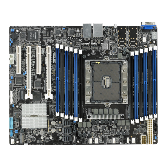
Page 24: Motherboard Layout
2.2.3 Motherboard layout Z11PA-U12/10G-2S Chapter 2: Hardware Information... - Page 25 Z11PA-U12 Z11PA-U12 Series...
-
Page 26: Layout Contents
2.2.4 Layout contents Slots/Sockets Page CPU socket DDR4 sockets 2-10 PCI Express x16 / PCI Express x8 2-12 Onboard LEDs Page Standby Power LED (SBPWR1) 2-16 Baseboard Management Controller LED (BMCLED1) 2-16 CATT LED (CATERR1) 2-17 Hard disk activity LED (HDDLED1) 2-17 Message LED (MESLED1) 2-18 Location LED (LOCLED1) 2-18 Q-Code LEDs (PORT80_LED1) 2-19 Jumpers Page Clear RTC RAM (CLRTC1) 2-19 VGA controller setting (3-pin VGA_SW1) 2-20 LAN controller setting (3-pin LAN_SW1, LAN_SW2) 2-20 ME firmware force recovery setting (3-pin ME_RCVR1) 2-21 DDR4 thermal event setting (3-pin DIMMTRIP1) 2-21 PCH_MFG1 setting (3-pin PCH_MFG1) 2-22 Smart Ride Through (SmaRT) setting (3-pin SMART_PSU1) - Page 27 13. System panel connector (20-1 pin PANEL1) 2-34 14. Auxiliary panel connector (20-2 pin AUX_PANEL1) 2-35 15. VPP_I2C1 connector (10-1 pin VPP_I2C1) 2-36 16. Chassis Intrusion (2-pin INTRUSION) 2-36 17. OCUPCIE connectors (OCUPCIE1-2) 2-37 18. System Management Bus (SMBUS) connectors (5-1 pin SMBUS1; 2-37 6-1 pin SMBUS2) 19. Serial General Purpose Input/Output connector (6-1 pin SSGPIO1) 2-38 20. VGA connector (16-pin VGA_HDR1) 2-38 21. VROC_KEY connector (4-pin VROC_KEY1) 2-39 22. Thermal sensor cable connector (3-pin TR1) 2-39 Z11PA-U12 Series...
-
Page 28: Central Processing Unit (Cpu)
The motherboard comes with a surface mount designed for the Socket P0 (LGA 3647) Intel ® Xeon processor Skylake-SP product family ® • Upon purchase of the motherboard, ensure that the PnP cap is on the socket and the socket contacts are not bent. Contact your retailer immediately if the PnP cap is missing, or if you see any damage to the PnP cap/socket contacts/motherboard components. ASUS will shoulder the cost of repair only if the damage is shipment/ transit-related. • Keep the cap after installing the motherboard. ASUS will process Return Merchandise Authorization (RMA) requests only if the motherboard comes with the cap on the Socket P0 (LGA 3647). • The product warranty does not cover damage to the socket contacts resulting from incorrect CPU installation/removal, or misplacement/loss/incorrect removal of the PnP cap. 2.3.1 Installing the CPU and heatsink To install a CPU: Locate the CPU socket on the motherboard. - Page 29 Twist each of the four screws with a screwdriver just enough to attach the heatsink to the motherboard. When the four screws are attached, tighten them one by one in a diagonal sequence to completely secure the heatsink. The CPU and heatsink assembly fits in only one correct orientation. DO NOT force the CPU and heatsink assembly into the socket to prevent damaging the CPU pins on the socket. The heatsink screws are T30 models. A torque value of 12 inch-lbf is recommended. Z11PA-U12 Series...
-
Page 30: System Memory
System memory 2.4.1 Overview The motherboard comes with twelve (12) Double Data Rate 4 (DDR4) Dual Inline Memory Modules (DIMM) sockets. The figure illustrates the location of the DDR4 DIMM sockets: 2.4.2 Memory Configurations You may install 4 GB, 8 GB, 16 GB, and 32 GB RDIMMs or 32 GB and 64 GB LR-DIMMs into the DIMM sockets using the memory configurations in this section. • Refer to ASUS Server AVL for the updated list of compatible DIMMs. • When installing DIMMs, always start from slot A1. • Always install DIMMs with the same CAS latency. For optimum compatibility, it is recommended that you obtain memory modules from the same vendor. You can refer to the following recommended memory population: Recommended Memory configuration DIMM 1 DIMM 2 DIMMs 4 DIMMs 6 DIMMs... -
Page 31: Installing A Dimm On A Single Clip Dimm Socket
Locked Retaining Clip Always insert the DIMM into the socket VERTICALLY to prevent DIMM notch damage. • To install two or more DIMMs, refer to the user guide bundled with the motherboard package. • Refer to the user guide for qualified vendor lists of the memory modules. Removing a DIMM from a single clip DIMM socket Press the retaining clip outward to unlock the DIMM. Remove the DIMM from the socket. Support the DIMM lightly with your fingers when pressing the retaining clips. The DIMM might get damaged when it flips out with extra force. Z11PA-U12 Series 2-11... -
Page 32: Expansion Slots
Expansion slots In the future, you may need to install expansion cards. The following subsections describe the slots and the expansion cards that they support. Ensure to unplug the power cord before adding or removing expansion cards. Failure to do so may cause you physical injury and damage motherboard components. 2.5.1 Installing an expansion card To install an expansion card: Before installing the expansion card, read the documentation that came with it and make the necessary hardware settings for the card. -
Page 33: Interrupt Assignments
2.5.5 PCI Express x8 slot (x8 link) The onboard PCIE3 slot provides one x8 Gen3 link to CPU1. This slot supports VGA cards and various server class high performance add-on cards. 2.5.6 PCI Express x8 slot (x4 link) The onboard PCIE1 slot provides one x4 Gen3 link to CPU1 This slot supports various server class high performance add-on cards. Z11PA-U12 Series 2-13... - Page 34 No. (Slot location) Short description PCI-E x16 (x16 Gen3 Link) PCIE4 (Auto switch to x8 Gen3 Link if slot 3 is occupied) (support riser) PCIE3 PCI-E x8 (x8 Gen3 Link) PCIE2 PCI-E x16 (x16 Gen3 Link) PCIE1 PCI-E x8 (x4 Gen3 Link) Chapter 2: Hardware Information 2-14...
-
Page 35: Onboard Leds
The illustration below shows the location of the onboard LED. Baseboard Management Controller LED (BMCLED1) The green heartbeat LED blinks per second to indicate that the ASMB9 is working normally. Z11PA-U12 Series 2-15... -
Page 36: Catt Led (Caterr1)
CATT LED (CATERR1) The CATT LED indicates that the system has experienced a fatal or catastrophic error and cannot continue to operate. Hard disk activity LED (HDDLED1) This LED is for the storage devices connected to the onboard SATA, or SATA/SAS add-on card. The read or write activities of any device connected to the onboard SATA, or SATA/SAS add-on card causes the rear panel LED to light up. Chapter 2: Hardware Information 2-16... -
Page 37: Message Led (Mesled1)
Message LED (MESLED1) This onboard LED lights up to red when there is a BMC event log is generated. Location LED (LOCLED1) This onboard LED lights up when the Location button on the server is pressed or when triggered by a system management software. The Location LED helps visually locate and quickly identify the server in error on a server rack. Z11PA-U12 Series 2-17... -
Page 38: Q-Code Leds (Port80_Led1)
Q-Code LEDs (PORT80_LED1) The Q-Code LED provides a 2-digit display that shows the status of your system. • The Q-Code LEDs provide the most probable cause of an error code as a starting point for troubleshooting. The actual cause may vary from case to case. • Please refer to the Q-Code table in the Appendix section for more details. Chapter 2: Hardware Information 2-18... -
Page 39: Jumpers
Turn OFF the computer and unplug the power cord. Move the jumper cap from the default pins 1–2 to pins 2–3. Keep the cap on pins 2–3 for about 5 to 10 seconds, then move the cap back to pins 1–2. Plug the power cord and turn ON the computer. Hold down the <Del> key during the boot process and enter BIOS setup to re- enter data. DO NOT remove the cap on CLRTC1 jumper default position except when clearing the RTC RAM. Removing the cap will cause system boot failure! If the steps above do not help, remove the onboard battery and move the jumper again to clear the CMOS RTC RAM data. After the CMOS clearance, reinstall the battery. Z11PA-U12 Series 2-19... -
Page 40: Vga Controller Setting (3-Pin Vga_Sw1)
VGA controller setting (3-pin VGA_SW1) This jumper allows you to enable or disable the onboard VGA controller. Set to pins 1–2 to activate the VGA feature. LAN controller setting (3-pin LAN_SW1, LAN_SW2) These jumpers allow you to enable or disable the onboard LAN_SW1 or LAN_SW2. Set to pins 1–2 to activate the Gigabit LAN feature. Chapter 2: Hardware Information 2-20... -
Page 41: Me Firmware Force Recovery Setting (3-Pin Me_Rcvr1)
ME firmware force recovery setting (3-pin ME_RCVR1) ® This jumper allows you to force Intel Management Engine (ME) boot from recovery mode when ME becomes corrupted. DDR4 thermal event setting (3-pin DIMMTRIP1) This jumper allows you to enable or disable DDR4 DIMM thermal sensing event pin. Z11PA-U12 Series 2-21... -
Page 42: Pch_Mfg1 Setting (3-Pin Pch_Mfg1)
PCH_MFG1 setting (3-pin PCH_MFG1) This jumper allows you to update the BIOS ME block. Smart Ride Through (SmaRT) setting (3-pin SMART_PSU1) This jumper allows you to enable or disable the Smart Ride Through (SmaRT) function. This feature is disabled by default. Set to pins 1-2 to enable it. When enabled, SmaRT allows uninterrupted operation of the system during an AC loss event. Chapter 2: Hardware Information 2-22... -
Page 43: Dmlan Setting (3-Pin Dm_Ip_Sel1)
DMLAN setting (3-pin DM_IP_SEL1) This jumper allows you to select the DMLAN setting. Set to pins 2-3 to force the DMLAN IP to static mode (IP=10.10.10.10, submask=255.255.255.0). IPMI SW setting (3-pin IPMI_SW1) This jumper allows you to select which protocol in the GPU sensor to function. Z11PA-U12 Series 2-23... -
Page 44: Baseboard Management Controller Setting (3-Pin Bmc_En1)
Baseboard Management Controller setting (3-pin BMC_EN1) This jumper allows you to enable (default) or disable on-board BMC. Ensure to set this BMC jumper to enabled to avoid system fan control and hardware monitor error. 10GbE LAN setting (3-pin SU1NCSI_EN1) (for Z11PA-U12/10G-2S only) This jumper allows you to enable 10GbE share LAN on BMC. Chapter 2: Hardware Information 2-24... -
Page 45: Lanncsi Setting (3-Pin Lan1_Ncsi_En; Lan2_Ncsi_En)
LANNCSI setting (3-pin LAN1_NCSI_EN; LAN2_NCSI_EN) This jumper allows you to select which LAN NCSI to function. For Z11PA-U12/10G-2S For Z11PA-U12 Z11PA-U12 Series 2-25... -
Page 46: Connectors
Connectors 2.8.1 Rear panel connectors Video Graphics Adapter (VGA) port: This port is for a VGA monitor or other VGA- compatible devices.. SFP+ LEDs (only available for Z11PA U12/10G-2S): These LEDs indicate the link status and the link speed of the SFP+ ports. Refer to the table below for the SFP+ LED indications. - Page 47 1 Gbps connection SFP+_LED indications (only available for Z11PA U12/10G-2S) Activity LED Speed LED Activity LED Status Description Status Description Speed LED No activity SFP+ LED BLINKING Data activity AMBER 1 Gbps connection GREEN 10 Gbps connection Z11PA-U12 Series 2-27...
-
Page 48: Internal Connectors
2.8.2 Internal connectors Serial ATA connectors (7-pin SSATA1) ® This connector, controlled by Intel C620 chipset, is for the Serial ATA signal cable for Serial ATA hard disk drives. Mini-SAS HD connector (ISATA1-2; ISSATA1) This motherboard comes with mini Serial Attached SCSI (SAS) HD connectors, the storage technology that supports Serial ATA. Each connector supports up to four devices. Chapter 2: Hardware Information 2-28... -
Page 49: Ngff) Connector (Ngff1)
M.2 (NGFF) connector (NGFF1) This connector allows you to install an M.2 device. This connector supports type 2242 / 2260 / 2280 devices on both PCI-E (2 lanes only) and SATA interface. The M.2 (NGFF) device is purchased separately. Trusted Platform Module connector (14-1 pin TPM1) This connector supports a Trusted Platform Module (TPM) system, which can securely store keys, digital certificates, passwords, and data. A TPM system also helps enhance network security, protects digital identities, and ensures platform integrity. Z11PA-U12 Series 2-29... -
Page 50: Usb 2.0 Connector (10-1 Pin Usb56)
USB 2.0 connector (10-1 pin USB56) This connector is for USB 2.0 ports. Connect the USB module cable to the connector, and then install the module to a slot opening at the back of the system chassis. The USB connectors comply with USB 2.0 specification that supports up to 480 Mbps connection speed. The USB port module is purchased separately. USB 3.0 connector (20-1 pin USB3_34) This connector allows you to connect a USB 3.0 module for additional USB 3.0 front or rear panel ports. With an installed USB 3.0 module, you can enjoy all the benefits of USB 3.0 including faster data transfer speeds of up to 5Gbps, faster charging time for USB-chargeable devices, optimized power efficiency, and backward compatibility with USB 2.0. The USB port module is purchased separately. Chapter 2: Hardware Information 2-30... -
Page 51: Power Supply Smbus Connector (5-Pin Psusmb1)
Power Supply SMBus connector (5-pin PSUSMB1) This connector allows you to connect SMBus (System Management Bus) to the PSU (power supply unit) to read PSU information. Devices communicate with an SMBus host and/or other SMBus devices using the SMBus interface. Power supply is required to meet PMBus specification and customized BMC FW may be needed. Please contact ASUS if your need further support. Serial port connector (10-1 pin COM1) This connector is for the serial COM port. Connect the serial port module cable to one of these connectors, then install the module to a slot opening at the back of the system chassis. The COM module is purchased separately. Z11PA-U12 Series 2-31... -
Page 52: Cpu, Front, And Rear Fan Connectors
• These are not jumpers! DO NOT place jumper caps on the fan connectors! • All fans feature the ASUS Smart Fan technology. Hard disk activity LED connector (4-pin HDLED1) This LED connector is for the storage add-on card cable connected to the SATA or SAS add-on card. The read or write activities of any device connected to the SATA or SAS add-on card causes the front panel LED to light up. -
Page 53: Eatx Power Connectors (24-Pin Eatxpwr, 8-Pin Eatx12V1)
• DO NOT forget to connect the 24+8-pin power plugs when using 85W or below CPU; otherwise, the system will not boot up. • Use of a PSU with a higher power output is recommended when configuring a system with more power-consuming devices. The system may become unstable or may not boot up if the power is inadequate. • Ensure that your power supply unit (PSU) can provide at least the minimum power required by your system. LAN34_LED connector (5-1 pin LAN34_LED1) These LEDs are for Gigabit LAN activity LEDs on the front panel. Connect the LAN LED cable to the backplane for LAN activity indication. Z11PA-U12 Series 2-33... -
Page 54: System Panel Connector (20-1 Pin Panel1)
System panel connector (20-1 pin PANEL1) This connector supports several chassis-mounted functions. System power LED (3-pin PLED) This 3-pin connector is for the system power LED. Connect the chassis power LED cable to this connector. The system power LED lights up when you turn on the system power, and blinks when the system is in sleep mode. Message LED (2-pin MLED) This 2-pin connector is for the message LED cable that connects to the front message LED. The message LED is controlled by Hardware monitor to indicate an abnormal event occurance. -
Page 55: Auxiliary Panel Connector (20-2 Pin Aux_Panel1)
These connectors are for Gigabit LAN activity LEDs on the front panel. Locator LED (2-pin LOCATORLED1, LOCATORLED2) These connectors are for the locator LED1 and LED2 on the front panel. Connect the Locator LED cables to these 2-pin connector. The LEDs will light up when the Locator button is pressed. Locator Button/Switch (2-pin LOCATORBTN) These connectors are for the locator button on the front panel. This button queries the state of the system locator. Z11PA-U12 Series 2-35... -
Page 56: Vpp_I2C1 Connector (10-1 Pin Vpp_I2C1)
VPP_I2C1 connector (10-1 pin VPP_I2C1) This connector is used for the Intel VMD function and sensor readings. Chassis Intrusion (2-pin INTRUSION1) These leads are for the intrusion detection feature for chassis with intrusion sensor or microswitch. When you remove any chassis component, the sensor triggers and sends a high level signal to these leads to record a chassis intrusion event. The default setting is short CHASSIS# and GND pin by jumper cap to disable the function. -
Page 57: Ocupcie Connectors (Ocupcie1-2)
Connects the PCIE signal to the front riser card or NVME port on the backplane. System Management Bus (SMBUS) connectors (5-1 pin SMBUS1; 6-1 pin SMBUS2) These connectors control the system and power management-related tasks. These connectors process the messages to and from devices rather than tripping the individual control lines. Z11PA-U12 Series 2-37... -
Page 58: Serial General Purpose Input/Output Connector (6-1 Pin Ssgpio1)
Serial General Purpose Input/Output connector (6-1 pin SSGPIO1) The SSGPIO 1 connector is used for the Intel Rapid Storage Technology Enterprise SGPIO interface that controls the LED pattern generation, device information, and general purpose data. VGA connector (16-pin VGA_HDR1) This connector supports the VGA High Dynamic-Range interface. Chapter 2: Hardware Information 2-38... -
Page 59: Vroc_Key Connector (4-Pin Vroc_Key1)
VROC_KEY connector (4-pin VROC_KEY1) This connector allows you to connect a KEY module to support Intel VMD RAID function. Thermal sensor cable connector (3-pin TR1) This connector allows you to connect a Thermal sensor cable that is used for temperature monitoring. Connect the Thermal sensor cable to the connector and place its probe to the device that you want to check the temperature. Z11PA-U12 Series 2-39... - Page 60 Chapter 2: Hardware Information 2-40...
-
Page 61: Chapter 3: Powering Up
Chapter 3: Powering Up Powering Up This chapter describes the power up sequence, and ways of shutting down the system. -
Page 62: Starting Up For The First Time
Starting up for the first time After making all the connections, replace the system case cover. Be sure that all switches are off. Connect the power cord to the power connector at the back of the system chassis. Connect the power cord to a power outlet that is equipped with a surge protector. Turn on the devices in the following order: Monitor External storage devices (starting with the last device on the chain) -
Page 63: Powering Off The Computer
While the system is ON, press the power switch for less than four seconds to put the system to sleep mode or to soft-off mode, depending on the BIOS setting. Pressing the power switch for more than four seconds lets the system enter the soft-off mode regardless of the BIOS setting. Z11PA-U12 Series... - Page 64 Chapter 3: Powering Up...
-
Page 65: Chapter 4: Bios Setup
Chapter 4: BIOS Setup BIOS Setup This chapter tells how to change the system settings through the BIOS Setup menus. Detailed descriptions of the BIOS parameters are also provided. -
Page 66: Managing And Updating Your Bios
BIOS in the future. Copy the original motherboard BIOS using the BUPDATER utility. 4.1.1 ASUS CrashFree BIOS 3 utility The ASUS CrashFree BIOS 3 is an auto recovery tool that allows you to restore the BIOS file when it fails or gets corrupted during the updating process. You can update a corrupted BIOS file using a USB flash drive that contains the updated BIOS file. -
Page 67: Asus Ezflash Utility
ASUS EzFlash Utility The ASUS EzFlash Utility feature allows you to update the BIOS using a USB flash disk without having to use a DOS-based utility. Download the latest BIOS from the ASUS website at www.asus.com before using this utility. The succeeding BIOS screens are for reference only. The actual BIOS screen displays may not be the same as shown. -
Page 68: Bupdater Utility
The BUPDATER utility allows you to update the BIOS file in DOS environment using a bootable USB flash disk drive with the updated BIOS file. Updating the BIOS file To update the BIOS file using the BUPDATER utility: Visit the ASUS website at www.asus.com and download the latest BIOS file for the motherboard. Save the BIOS file to a bootable USB flash disk drive. Download the BUPDATER utility (BUPDATER.exe) from the ASUS support website at support.asus.com to the bootable USB flash disk drive you created earlier. Boot the system in DOS mode, then at the prompt, type: BUPDATER /i[filename].CAP where [filename] is the latest or the original BIOS file on the bootable USB flash disk drive, then press <Enter>. A:\>BUPDATER /i[file name]CAP... - Page 69 The utility verifies the file, then starts updating the BIOS file. ASUS Tek. EzFlash Utility Current Platform New Platform Platform : Z11PA-U12 Platform : Z11PA-U12 Version : 0106 Version : 0204 Build date: 06/21/2017 Build date: 07/24/2017 Start Programming Flash. DO NOT SHUTDOWN THE SYSTEM!!! Write DO NOT shut down or reset the system while updating the BIOS to prevent system boot failure! The utility returns to the DOS prompt after the BIOS update process is completed.
-
Page 70: Bios Setup Program
Press <F5> and select Yes to load the BIOS default settings. • The BIOS setup screens shown in this section are for reference purposes only, and may not exactly match what you see on your screen. • Visit the ASUS website (www.asus.com) to download the latest BIOS file for this motherboard. Chapter 4: BIOS Setup... -
Page 71: Bios Menu Screen
For changing the event log settings For changing the server mgmt settings Server Mgmt Security For changing the security settings Boot For changing the system boot configuration Tool For configuring options for special functions Save & Exit For selecting the save & exit options To select an item on the menu bar, press the right or left arrow key on the keyboard until the desired item is highlighted. Z11PA-U12 Series... -
Page 72: Menu Items
4.2.3 Menu items The highlighted item on the menu bar displays the specific items for that menu. For example, selecting Main shows the Main menu items. The other items (Advanced, Platform Configuration, Socket Configuration, Event Logs, Server Mgmt, Security, Boot, Tool, and Save & Exit) on the menu bar have their respective menu items. 4.2.4 Submenu items A solid triangle before each item on any menu screen means that the item has a submenu. To display the submenu, select the item then press <Enter>. -
Page 73: Main Menu
4.3.1 System Date [Day xx/xx/xxxx] Allows you to set the system date. 4.3.2 System Time [xx:xx:xx] Allows you to set the system time. Z11PA-U12 Series... -
Page 74: Advanced Menu
Advanced menu The Advanced menu items allow you to change the settings for the CPU and other system devices. Take caution when changing the settings of the Advanced menu items. Incorrect field values can cause the system to malfunction. 4.4.1 Trusted Computing Configuration Security Device Support [Enabled] Allows you to enable or disable the BIOS support for security device. Configuration options: [Disabled] [Enabled] Chapter 4: BIOS Setup 4-10... -
Page 75: Acpi Settings
Allows you to select the highest ACPI sleep state the system will enter when the SUSPEND button is pressed. Configuration options: [Suspend Disabled] [S3 (Suspend to RAM)] 4.4.3 Smart Settings SMART Self Test [Enabled] Allows you to run SMART Self Test on all HDDs during POST. Configuration options: [Disabled] [Enabled] Z11PA-U12 Series 4-11... -
Page 76: Super Io Configuration
4.4.4 Super IO Configuration Serial Port 1 Configuration Allows you to set the parameters of Serial Port 1. Serial Port [Enabled] Allows you to enable or disable Serial Port. Configuration options: [Disabled] [Enabled] The following item appears only when you set Serial Port to [Enabled]. Change Settings [Auto] Allows you to choose the setting for Super IO device. - Page 77 Parity [None] A parity bit can be sent with the data bits to detect some transmission errors. [Mark] and [Space] parity do not allow for error detection. [None] None. [Even] parity bit is 0 if the num of 1’s in the data bits is even. [Odd] parity bit is 0 if num of 1’s in the data bits is odd. [Mark] parity bit is always 1. [Space] parity bit is always 0. Stop Bits [1] Stop bits indicate the end of a serial data packet. (A start bit indicates the beginning.) The standard setting is 1 stop bit. Communication with slow devices may require more than 1 stop bit. Configuration options: [1] [2] Z11PA-U12 Series 4-13...
- Page 78 Flow Control [Hardware RTS/CTS] Flow control can prevent data loss from buffer overflow. When sending data, if the receiving buffers are full, a “stop” signal can be sent to stop the data flow. Once the buffers are empty, a “start” signal can be sent to re-start the flow. Hardware flow control uses two wires to send start/stop signals. Configuration options: [None] [Hardware RTS/CTS] VT-UTF8 Combo Key Support [Enabled] Allows you to enable the VT-UTF8 Combo Key Support for ANSI/VT100 terminals. Configuration options: [Disabled] [Enabled] Recorder Mode [Disabled] With this mode enabled only text will be sent. This is to capture Terminal data. Configuration options: [Disabled] [Enabled] Legacy OS Redirection Resolution [80x24] This allows you to set the number of rows and columns supported on the Legacy OS.
-
Page 79: Onboard Lan
Allows you to set the terminal type for out-of-band management. Configuration options: [VT100] [VT100+] [VT-UTF8] [ANSI] Bits per second [115200] Allows you to set the serial port transmission speed. Configuration options: [9600] [19200] [57600] [115200] Flow Control [None] Allows you to set the flow control to prevent data loss from buffer overflow. Configuration options: [None] [Hardware RTS/CTS] [Software Xon/Xoff] 4.4.6 Onboard LAN Onboard I210 LAN Configuration Z11PA-U12 Series 4-15... - Page 80 Intel LAN1 Enable [Enabled] Allows you to enable or disable the Intel LAN. Configuration options: [Disabled] [Enabled] The following item appears only when you set Intel LAN1 Enable to [Enabled]. Intel LAN ROM Type [PXE] Allows you to select the Intel LAN ROM type. Configuration options: [Disabled] [PXE] [iSCSI] ® Due to Intel limitations, both Intel LAN ROM Type options should be the same when [PXE] or [iSCSI] is selected. Intel LAN2 Enable [Enabled] Allows you to enable or disable the Intel LAN. Configuration options: [Disabled] [Enabled] The following item appears only when you set Intel LAN2 Enable to [Enabled].
-
Page 81: Apm
AC power loss. Configuration options: [Power Off] [Power On] [Last State] Power On By PCIE [Disabled] [Disabled] Disables the PCIE devices to generate a wake event. [Enabled] Enables the PCIE devices to generate a wake event. Power On By RTC [Disabled] [Disabled] Disables RTC to generate a wake event. [Enabled] W hen set to [Enabled], the items RTC Alarm Date (Days) and Hour/Minute/Second will become user-configurable with set values. Z11PA-U12 Series 4-17... -
Page 82: Pci Subsystem Settings
4.4.8 PCI Subsystem Settings Allows you to configure PCI, PCI-X, and PCI Express Settings. Load RT32 Image [Disabled] Allows you to enable or disable RT32 Image Loading. Configuration options: [Disabled] [Enabled] Above 4G Decoding [Disabled] Allows you to enable or disable 64-bit capable devices to be decoded in above 4G address space. It only works if the system supports 64-bit PCI decoding. Configuration options: [Disabled] [Enabled] SR-IOV Support [Enabled] This option enables or disables SIngle Root IO Virtualization Support if the system has SRIOV capable PCIe devices. - Page 83 PCI Express Gen 2 Settings PCI Express GEN2 Device Register Settings Completion Timeout [Default] This option allows system software to modify the Completion Timeout value for device Functions which support Completion Timeout programmability. [Default] 50us to 50ms. [Shorter] Shorter timeout ranges supported by hardware will be used. [Longer] Longer timeout ranges supported by hardware will be used. [Disabled] Disable Completion Timeout. Z11PA-U12 Series 4-19...
- Page 84 ARI Forwarding [Disabled] If supported by hardware and set to Enabled, the Downstream Port disables its traditional Device Number filed being 0 enforcement when turning a Type1 Configuration Request into a Type0 Configuration Request, permitting access to Extended Functions in an ARI Device immediately below the Port. Configuration options: [Disabled] [Enabled] Atomic0p Request Enable [Disabled] If supported by hardware and set to Enabled, this function initiates Atomic0p Requests only if Bus Master Enable bit is in the Command Register Set.
- Page 85 Hardware Autonomous Speed [Enabled] If supported by hardware and set to Disabled, this will disable the hardware’s ability to change link speed except for speed rate reduction for the purpose of correcting unstable link operation. Configuration options: [Disabled] [Enabled] PCIE OPROM Slot Options PCIE1-6 Slot OPROM [Enabled] This option allows you to enable or disable the OPROM of the PCIe slots. Configuration options: [Disabled] [Enabled] Z11PA-U12 Series 4-21...
-
Page 86: Network Stack Configuration
4.4.9 Network Stack Configuration Allows you to configure the netword stack configuration. Network Stack [Disabled] Allows you to enable or disable UEFI Network Stack. Configuration options: [Disabled] [Enabled] The following items appear only when you set the Network Stack to [Enabled]. Ipv4 PXE Support [Disabled] Enables or disables the Ipv4 PXE Boot Support. If disabled, Ipv4 PXE boot option will not be created. Configuration options: [Disable] [Enable] Ipv4 HTTP Support [Disabled] Enables or disables the Ipv4 HTTP Boot Support. If disabled, Ipv4 PXE boot option will not be created. Configuration options: [Disable] [Enable] Ipv6 PXE Support [Disabled] Enables or disables the Ipv6 PXE Boot Support. If disabled, Ipv6 PXE boot option will... -
Page 87: Csm Configuration
This option allows you to control the BIOS reaction on INT19 trapping by Option ROM. [Immediate] Execute the trap right away. [Legacy only] Execute the trap during legacy boot. Boot Option filter [Legacy only] This option allows you to control the Legacy/UEFI ROMs priority. Configuration options: [UEFI and Legacy] [Legacy only] [UEFI only] Network / Storage / Video [Legacy] This option allows you to control the execution of UEFI and Legacy PXE/ Storage/ Video OpROM. Configuration options: [UEFI ] [Legacy] Other PCI devices [Legacy] This item determines the OpROM execution policy for devices other than Network, Storage, or Video. Configuration options: [UEFI ] [Legacy] Z11PA-U12 Series 4-23... -
Page 88: Nvme Configuration
4.4.11 NVMe Configuration You may view the NVMe controller and Drive information if an NVMe device is connected. 4.4.12 USB Configuration Legacy USB Support [Enabled] [Disabled] The USB devices can be used only for the BIOS setup program. It cannot be recognized in boot devices list. [Enabled] Enables the support for USB devices on legacy operating systems (OS). [Auto] Allows the system to detect the presence of USB devices at startup. If detected, the USB controller legacy mode is enabled. If no USB device is detected, the legacy USB support is disabled. -
Page 89: Iscsi Configuration
4.4.13 iSCSI Configuration Allows you to configure the iSCSi parameters. 4.4.14 Intel(R) Virtual RAID on CPU Allows you to configure the view the RAID volumes and VMD controllers on the system. Z11PA-U12 Series 4-25... -
Page 90: Platform Configuration Menu
Platform Configuration menu The IntelRCSetup menu items allow you to change the platform settings. Take caution when changing the settings of the Platform Configuration menu items. Incorrect field values can cause the system to malfunction. 4.5.1 PCH Configuration PCH Devices Board Capability [DeepSx] [SUS_PWR_DN_ACK] Send. [DeepSx] Show DeepSx Policies. DeepSx Power Policies [Disabled] Allows you to configure the DeepSx Mode configuration. Configuration options: [Disabled] [Enabled in S5] [Enabled in S4 and S5] GP27 Wake From DeepSx [Disabled] Allows you to enable or disable GP27 Wake From DeepSx. Configuration options: [Disabled] [Enabled] PCI Express Configuration PCI-E ASPM Support (Global) [L1 Only]... - Page 91 Allows you to identify the SATA port connected to Solid State Drive or Hard Disk Drive. Configuration options: [AHCI] [RAID] Support Aggressive Link Power Management [Enabled] Allows you to enable or disable the Support Aggressive Link Power (SALP) Management. Configuration options: [Disabled] [Enabled] sSATA Port 0-5 Port 0-5 Allows you to enable or disable the SATA port. Configuration options: [Disabled] [Enabled] USB Configuration USB Precondition [Disabled] Allows you to enable or disable precondition work on USB host controller and root ports for faster enumeration. Configuration options: [Disabled] [Enabled] Z11PA-U12 Series 4-27...
- Page 92 XHCI Manual Mode [Disabled] This option is used by validation. Configuration options: [Disabled] [Enabled] The following items appear only when the XHCI Manual Mode is set to [Enabled]. Trunk Clock Gating (BTCG) [Enabled] Allows you to enable or disable BTCG. Configuration options: [Disabled] [Enabled] Enable USB 3.0 pins [Disable all pins] Allows you to enable or disable USB 3.0 pins or on a per pin basis.
-
Page 93: Miscellaneous Configuration
Displays the Server ME Technology parameters on your system. Navigate to the second page of the screen to see the rest of items in this menu by pressing the Up or Down arrow keys. To quickly go to the last item of the second page, press the Page Down button. Press the Page Up button to go back to the first item in the first page. Z11PA-U12 Series 4-29... -
Page 94: Runtime Error Logging
4.5.4 Runtime Error Logging Displays the Server ME Technology parameters on your system. System Errors [Enabled] This item allows you to enable or disable System Errors. Configuration options: [Disabled] [Enabled] Whea Settings Whea Support [Enabled] This item allows you to enable or disable the WHEA support. Configuration options: [Disabled] [Enabled] Chapter 4: BIOS Setup 4-30... -
Page 95: Socket Configuration Menu
Navigate to the second page of the screen to see the rest of items in this menu by pressing the Up or Down arrow keys. To quickly go to the last item of the second page, press the Page Down button. Press the Page Up button to go back to the first item in the first page. Hyper-threading [ALL] [Enabled] This item allows a hyper-threading processor to appear as two logical processors, allowing the operating system to schedule two threads or processors simultaneously. Configuration options: [Disabled] [Enabled] Z11PA-U12 Series 4-31... - Page 96 Execute Disable Bit [Enabled] XD can prevent certain classes of malicious buffer overflow attacks when combined with a supporting OS (Windows Server 2003 SP1, Windows XP SP2, SuSE Linux 9.2, Redhat Enterprise 3 Update 3). Configuration options: [Disabled] [Enabled] Enable Intel(R) TXT [Disabled] Forces the XD feature log to always return 0 when disabled. Configuration options: [Disabled] [Enabled] VMX [Enabled] Enables the Vanderpool Technology. Takes effect after reboot. Configuration options: [Disabled] [Enabled] Enable SMX [Disabled] Enables the Safer Mode Extensions. Configuration options: [Disabled] [Enabled] Hardware Prefetcher [Enabled] This Item allows you to turn on/off the mid level cache(L2) streamer prefetcher. Configuration options: [Disabled] [Enabled] Adjacent Cache Prefetch [Enabled] This Item allows you to turn on/off prefetching of adjacent cache lines. Configuration options: [Disabled] [Enabled] DCU Streamer Prefetcher [Enabled] This Item allows you to enable or disable prefetcher of next L1 data line.
-
Page 97: Common Refcode Configuration
This item displays information about the UPI status. Link Speed Mode [Fast] This item allows you to select the UPI link speed as either the fast mode or slow mode. Configuration options: [Slow] [Fast] Link Frequency Select [Auto] This item allows for selecting the UPI link frequency. Configuration options: [Auto] [9.6 GB/s] [10.4 GB/s] [Use Per Link Setting] Link0p Enable [Auto] Configuration options: [Disabled] [Enabled] [Auto] Link1 Enable [Auto] Configuration options: [Disabled] [Enabled] [Auto] Stale AtoS [Disabled] Configuration options: [Disabled] [Enabled] [Auto] LLC dead line alloc [Enabled] Configuration options: [Disabled] [Enabled] [Auto] Z11PA-U12 Series 4-33... -
Page 98: Memory Configuration
4.6.4 Memory Configuration Enforce POR [Auto] Allows you to enforce POR restrictions for DDR4 frequency and voltage programming. Configuration options: [Auto] [POR] [Disabled] Memory Frequency [Auto] Allows you to select the memory frequency setting. Configuration options: [Auto] [2133] [2400] [2666] Data Scrambling for DDR4 [Auto] Allows you to enable or disable data scrambling. Configuration options: [Auto] [Disabled] [Enabled] Memory Topology Displays memory topology with DIMM population information. -
Page 99: Iio Configuration
Memory Rank Sparing [Disabled] Allows you to enable or disable Memory Rank Sparing Configuration options: [Disabled] [Enabled] Patrol Scrub [Enabled] Allows you to enable or disable Patrol Scrub. Configuration options: [Disabled] [Enabled] 4.6.5 IIO Configuration Socket1 Configuration This option allows you to change the settings related to the PCI Express Ports. Z11PA-U12 Series 4-35... -
Page 100: Advanced Power Management Configuration
Intel® VT for Directed I/O (VT-d) Intel® VT for Directed I/O (VT-d) [Enabled] Allows you to enable or disable the Intel Virtualization Technology for Directed I/O. Configuration options: [Disabled] [Enabled] IIO-PCIE Express Global Options PCIE relaxed Ordering [Enabled] Allows you to enable or disable PCIE relaxed Ordering. Configuration options: [Disabled] [Enabled] 4.6.6 Advanced Power Management Configuration... - Page 101 This option controls whether PECI has control over EPB. Configuration options: [OS Controls EPB] [PECI Controls EPB using PCS] The following item appears only when you set Power Performance Tuning to [BIOS Controls EPB]. ENERGY_PERF_BIAS_CFG Mode Configuration options: [Performance] [Balanced Performance] [Balanced Power] [Power] Dynamic Loadline Switch Configuration options: [Disabled] [Enabled] Workload Configuration This option allows optimization for the workload characterization. Configuration options: [UMA] [NUMA] Z11PA-U12 Series 4-37...
- Page 102 Averaging Time Window This option is used to control the effective window of the average C0 an P0 time. Configuration options: [0] - [99] P0 TotalTimeThreshold Low The HW switching mechanism DISABLES the performance setting (0) when the total P0 time is less than the threshold set. Configuration options: [0] - [99] P0 TotalTimeThreshold High The HW switching mechanism Enables the performance setting (0) when the total P0 time is greater than the threshold set. Configuration options: [0] - [99] Chapter 4: BIOS Setup 4-38...
-
Page 103: Event Logs Menu
Change Smbios Event Log Settings Press <Enter> to change the Smbios Event Log configuration. All values changed here do not take effect until computer is restarted. Enabling/Disabling Options Smbios Event Log [Enabled] Change this to enable or disable all features of Smbios Event Logging during boot. Configuration options: [Disabled] [Enabled] Erasing Settings Erase Event Log [No] Choose options for erasing Smbios Event Log. Erasing is done prior to any logging activation during reset. Configuration options: [No] [Yes, Next reset] [Yes, Every reset] 4.7.2 View Smbios Event Log Press <Enter> to view all smbios event logs. Z11PA-U12 Series 4-39... -
Page 104: Server Mgmt Menu
Server Mgmt menu OS Watchdog Timer [Disabled] This item allows you to start a BIOS timer which can only be shut off by Intel Management Software after the OS loads. Configuration options: [Disabled] [Enabled] The following items are configurable only when the OS Watchdog Timer is set to [Enabled]. OS Wtd Timer Timeout [10 minutes] Allows you to configure the length for the OS Boot Watchdog Timer. -
Page 105: Bmc Network Configuration
Navigate to the second page of the screen to see the rest of items in this menu by pressing the Up or Down arrow keys. To quickly go to the last item of the second page, press the Page Down button. Press the Page Up button to go back to the first item in the first page. IPV4 DM_LAN1/ Shared LAN Config Address source [Previous State] This item allows you to configure LAN channel parameters statistically or dynamically (by BIOS or BMC). Unspecified option will not modify any BMC network parameters during BIOS phase. Configuration options: [Previous State] [Static] [DynamicBmcDhcp] [DynamicBmcNonDhcp] IPV6 DM_LAN1/ Shared LAN IPV6 Support [Enabled] Allows you to enable or disable LAN1 IPV6 Support. Configuration options: [Disabled] [Enabled] Z11PA-U12 Series 4-41... -
Page 106: View System Event Log
Config Address source [Previous State] This item allows you to configure LAN channel parameters statistically or dynamically (by BIOS or BMC). Unspecified option will not modify any BMC network parameters during BIOS phase. Configuration options: [Previous State] [Static] [DynamicBmcDhcp] [DynamicBmcNonDhcp] 4.8.3 View System Event Log This item allows you to view the system event log records. Chapter 4: BIOS Setup 4-42... -
Page 107: Security Menu
1. Select the Administrator Password item and press <Enter>. 2. From the Create New Password box, key in a password, then press <Enter>. 3. Confirm the password when prompted. To change an administrator password: 1. Select the Administrator Password item and press <Enter>. 2. From the Enter Current Password box, key in the current password, then press <Enter>. 3. From the Create New Password box, key in a new password, then press <Enter>. 4. Confirm the password when prompted. To clear the administrator password, follow the same steps as in changing an administrator password, but press <Enter> when prompted to create/confirm the password. Z11PA-U12 Series 4-43... - Page 108 User Password To set a user password: 1. Select the User Password item and press <Enter>. 2. From the Create New Password box, key in a password, then press <Enter>. 3. Confirm the password when prompted. To change a user password: 1. Select the User Password item and press <Enter>. 2. From the Enter Current Password box, key in the current password, then press <Enter>. 3. From the Create New Password box, key in a new password, then press <Enter>. 4. Confirm the password when prompted. To clear a user password: 1.
- Page 109 This item will allow the image to run in Secure Boot mode. Save All Secure Boot Variables This item will ask you if you want to save all secure boot variables. Select Yes if you want to save all secure boot variables, otherwise select No. Platform Key (PK) Configuration options: [Save to File] [Set New] [Erase] Key Exchange Keys / Authorized Signatures / Forbidden Signatures Configuration options: [Save to File] [Set New] [Append] [Erase] Authorized TimeStamps Configuration options: [Set New] [Append] OsRecovery Signatures Configuration options: [Set New] [Append] Z11PA-U12 Series 4-45...
-
Page 110: Boot Menu
These items specify the boot device priority sequence from the available devices. The number of device items that appears on the screen depends on the number of devices installed in the system. • To select the boot device during system startup, press <F8> when ASUS Logo appears. • To access Windows OS in Safe Mode, please press <F8> after POST. Network Device BBS Priorities This item allows you to set the booting from network. -
Page 111: Tool Menu
<Enter> to display the submenu. IPMI HWM Allows you to run the IPMI hardware monitor. Start EzFlash Allows you to run ASUS EzFlash BIOS ROM Utility when you press <Enter>. Refer to the ASUS EzFlash Utility section for details. 4.12 Save & Exit menu The Exit menu items allow you to save or discard your changes to the BIOS items. - Page 112 Boot Override These items displays the available devices. The device items that appears on the screen depends on the number of devices installed in the system. Click an item to start booting from the selected device. Launch EFI Shell from filesystem device This item allows you to attempt to launch the EFI Shell application (shellx64.efi) from one of the available filesystem devices. Chapter 4: BIOS Setup 4-48...
-
Page 113: Chapter 5: Raid Configuration
Chapter 5: RAID Configuration RAID Configuration This chapter provides instructions for setting up, creating, and configuring RAID sets using the available utilities. -
Page 114: Raid Configurations
RAID configurations The motherboard supports Intel Rapid Storage Technology enterprise Option ROM Utility ® with RAID 0, RAID 1, RAID 10, and RAID 5 support. If you want to install a Windows operating system to a hard disk drive included in a RAID ®... -
Page 115: Installing Serial Ata Hard Disks
Rapid Storage Technology ® if you installed Serial ATA hard disk drives on the Serial ATA connectors supported by the Intel C620 chipset. ® Refer to the succeeding section for details on how to use the RAID configuration utility. Z11PA-U12 Series... -
Page 116: Intel
® Intel Rapid Storage Technology enterprise SATA/SSATA Option ROM Utility The Intel Rapid Storage Technology enterprise SATA/SSATA Option ROM utility allows you ® to create RAID 0, RAID 1, RAID 10 (RAID 1+0), and RAID 5 set from Serial ATA hard disk drives that are connected to the Serial ATA connectors supported by the Southbridge. -
Page 117: Creating A Raid Set
]-Prev/Next [TAB]-(M)aster [SPACE]-(R)ecovery [ENTER]-Done Use the up/down arrow keys to move the selection bar then press <Space> to select a disk. A small triangle before the Port number marks the selected drive. Press <Enter> when you are done. Z11PA-U12 Series... - Page 118 Use the up/down arrow keys to select the stripe size for the RAID array (for RAID 0, 10 and 5 only) then press <Enter>. The available stripe size values range from 4 KB to 128 KB. The following are typical values: RAID 0: 128KB RAID 10:...
-
Page 119: Deleting A Raid Set
<N> to return to the DELETE VOLUME menu. DELETE VOLUME VERIFICATION ALL DATA IN THE VOLUME WILL BE LOST! (This does not apply to Recovery volumes) Are you sure you want to delete volume “Volume0”? (Y/N): Z11PA-U12 Series... -
Page 120: Resetting Disks To Non-Raid
5.2.3 Resetting disks to Non-RAID Take caution before you reset a RAID volume hard disk drive to non-RAID. Resetting a RAID volume hard disk drive deletes all internal RAID structure on the drive. To reset a RAID set: From the utility main menu, select 3. Reset Disks to Non-RAID and press <Enter>. Press the up/down arrow keys to select the drive(s) or disks of the RAID set you want to reset, then press <Space>. -
Page 121: Exiting The Intel ® Rapid Storage Technology Enterprise
Rebuild completes in the operating system. Select the port of destination disk for rebuilding (ESC to exit): Port Drive Model Serial # Size XXXXXXXXXXX XXXXXXXX XXX.GB ]-Previous/Next [ENTER]-Select [ESC]-Exit Select a destination disk with the same size as the original hard disk. Z11PA-U12 Series... - Page 122 The utility immediately starts rebuilding after the disk is selected. When done, the status of the degraded RAID volume is changed to “Rebuild”. Intel(R) Rapid Storage Technology enterprise - SATA Option ROM - 3.6.0.1023 Copyright(C) 2003-12 Intel Corporation. All Rights Reserved. MAIN MENU 1.
-
Page 123: Setting The Boot Array In The Bios Setup Utility
Use up/down arrow keys to select the boot priority and press <Enter>. See the Boot menu section of Chapter 4 for more details. From the Exit menu, select Save Changes & Exit, then press <Enter>. When the confirmation window appears, select Yes, then press <Enter>. Z11PA-U12 Series 5-11... -
Page 124: Intel ® Rapid Storage Technology Enterprise (Windows)
® Intel Rapid Storage Technology enterprise (Windows) The Intel Rapid Storage Technology enterprise allows you to create RAID 0, RAID 1, RAID ® 10 (RAID 1+0), and RAID 5 set(s) from Serial ATA hard disk drives that are connected to the Serial ATA connectors supported by the Southbridge. -
Page 125: Creating A Raid Set
Select Volume Size tab, you can drag the bar to decide the volume size. Click Next. • If you do not want to keep the data on one of the selected disks, select NO when prompted. • If you want to Enable volume write-back cache or Initialize volume, click Advanced. Z11PA-U12 Series 5-13... - Page 126 Confirm the volume creation, than click Create Volume to continue. This process could take a while depending on the number and size of the disks. You can continue using other applications during this time. Wait until the process is completed, then click OK when prompted. You still need to partition your new volume using Windows Disk Management before adding any data.
-
Page 127: Changing A Volume Type
OK. The available stripe size values range from 4 KB to 128 KB. The following are typical values: RAID 0: 128KB RAID 10: 64KB RAID 5: 64KB We recommend a lower stripe size for server systems, and a higher stripe size for multimedia computer systems used mainly for audio and video editing. Z11PA-U12 Series 5-15... -
Page 128: Deleting A Volume
5.3.3 Deleting a volume Be cautious when deleting a volume. You will lose all data on the hard disk drives.Before you proceed, ensure that you back up all your important data from your hard drives. To delete a volume: From the utility main menu, select the volume (exp. Volume_0000) in Volumes field you want to delete. -
Page 129: Preferences
Allow you to set to show the notification area icon and show system information, warning, or errors here. E-Mail Preferences Allow you to set to sent e-mail of the following events: • Storage system information • Storage system warnings • Storage system errors Z11PA-U12 Series 5-17... -
Page 130: Intel ® Virtual Raid On Cpu In Bios
Intel Virtual Raid on CPU in BIOS ® This feature requires a KEY module to enable CPU RAID functions with Intel CPU RSTe. ® • The KEY module is purchased separately. • Refer to section 2.8.2 Internal connectors for the location of the VROC_HW_KEY connector. -
Page 131: Creating A Raid Set
RAID 0: 128 KB RAID 10: 64 KB RAID 5: 64 KB We recommend a lower strip size for server systems, and a higher strip size for multimedia computer systems used mainly for audio and video editing. Z11PA-U12 Series 5-19... - Page 132 When the Capacity (MB) item is selected, enter the RAID volume capacity that you want and press <Enter>. The default value indicates the maximum allowed capacity. When the Create Volume item is selected, press <Enter> to create the RAID volume and return to the Intel Rapid Storage Technology menu.
-
Page 133: Deleting A Raid Set
<Enter>. The following screen appears: When the Delete item is selected, press <Enter>, then select Yes to delete the RAID volume and return to the Intel Virtual Raid on CPU menu, or select No to cancel. ® Z11PA-U12 Series 5-21... -
Page 134: Installing The Raid Controller Driver During Windows
5.4.3 Installing the RAID controller driver during Windows ® 10 OS installation This part provides the instructions on how to install the RAID controller drivers during OS installation. To install the RAID controller driver when installing Windows 10 OS: ® Boot the computer using the Windows 10 OS installation disc. - Page 135 When the system finishes loading the RAID driver, replace the motherboard Support DVD with the Windows Server installation disc. Select the drive to install Windows and click Next. Setup then proceeds with the OS installation. Follow screen instructions to continue. Z11PA-U12 Series 5-23...
- Page 136 Chapter 5: RAID Configuration 5-24...
-
Page 137: Chapter 6: Driver Installation
Chapter 6: Driver Installation Driver Installation This chapter provides the instructions for installing the necessary drivers for different system components in the ® Windows Operating Systems. -
Page 138: Raid Driver Installation
RAID driver installation After creating the RAID sets for your server system, you are now ready to install an operating system to the independent hard disk drive or bootable array. This part provides the instructions on how to install the RAID controller drivers during OS installation. 6.1.1 Creating a USB flash drive with RAID drive ®... - Page 139 Click Browse to continue. Locate the driver in the corresponding folder of the Support DVD or USB flash drive and then click OK to continue. Select the RAID controller driver you need from the list and click Next. Z11PA-U12 Series...
- Page 140 When the system finishes loading the RAID driver, Replace the motherboard Support DVD with the Windows Server installation disc. • Remove the USB flash drive. • Select the drive to install Windows and click Next. Setup then proceeds with the OS installation. Follow screen instructions to continue. Chapter 6: Driver Installation...
-
Page 141: Management Applications And Utilities Installation
• The contents of the support DVD are subject to change at any time without notice. Visit the ASUS website (www.asus.com) for the latest updates on software and utilities. ®... - Page 142 6.3.1 Drivers menu tab The Drivers Menu shows the available device drivers if the system detects installed devices. Install the necessary drivers to activate the devices. 6.3.2 Utilities menu tab The Utilities menu displays the software applications and utilities that the motherboard supports. Chapter 6: Driver Installation...
- Page 143 You need an internet browser installed in your OS to view the User Guide. 6.3.4 Contact information menu The Contact menu displays the ASUS contact information, e-mail addresses, and useful links if you need more information or technical support for your motherboard. Z11PA-U12 Series...
-
Page 144: Intel ® Chipset Device Software Installation
Intel chipset device software installation ® This section provides the instructions on how to install the Intel chipset device software on ® the system. You need to manually install the Intel chipset device software on a Windows operating ® system. To install the Intel chipset device software: ®... - Page 145 Read the License Agreement and click Accept to continue the process. Read the Readme File Information and click Install to start the installation process. Click Restart Now to complete the setup process. Z11PA-U12 Series...
-
Page 146: Installing The Intel ® I210 Gigabit Adapters Driver
® Installing the Intel I210 Gigabit Adapters driver This section provides the instructions on how to install the Intel I210 Gigabits Adapter ® Driver on the system. To install the Intel I210 Gigabit Adapters Driver on the Windows operating system: ®... - Page 147 Tick I accept the terms in the license agreement and click Next to continue. From the Setup Options window, click Next to start the installation. By default, Intel(R) PROSet for Windows Device Manager and Windows PowerShell Module are ticked. Z11PA-U12 Series 6-11...
- Page 148 Click Install to start the installation. When the installation is done, press Finish to complete the installation. 6-12 Chapter 6: Driver Installation...
-
Page 149: Intel ® Rapid Storage Technology Enterprise 5.0 Installation
Insert the motherboard/system support DVD into the optical drive, and navigate to the Utilities menu. ® Click the Intel Rapid Storage Technology enterprise to begin installation. ® The Intel Rapid Storage Technology enterprise window appears. Click Next to start the installation. Z11PA-U12 Series 6-13... - Page 150 Read the Warning message and click Next to continue. Read the License Agreement and click Accept to continue the process. Select the destination folder and click Next to continue. 6-14 Chapter 6: Driver Installation...
- Page 151 Tick the features that you would like to install and click Next to continue. Click Install to start the installation process. Click Restart Now to complete the setup process. Z11PA-U12 Series 6-15...
- Page 152 6-16 Chapter 6: Driver Installation...
-
Page 153: Appendix
Appendix Appendix This appendix includes additional information that you may refer to when configuring the motherboard. -
Page 154: Z11Pa-U12 Series Block Diagram
Z11PA-U12 Series block diagram Z11PA-U12/10G-2S Appendix... -
Page 155: Z11Pa-U12
Z11PA-U12 Z11PA-U12 Series... -
Page 156: Q-Code Table
Q-Code table Action PHASE POST CODE TYPE DESCRIPTION Progress First post code(POWER_ON_POST_CODE) Progress Load BSP microcode(MICROCODE_POST_CODE) Progress Set cache as ram for PEI phase(CACHE_ENABLED_POST_CODE) Security Phase Progress CPU Early init.(CPU_EARLY_INIT_POST_CODE) Progress initializes South bridge for PEI preparation Progress PEI Core Entry Progress NB initialize before installed memory Progress... - Page 157 IDE, AHCI Init. Progress BIOS Setup Utility password verify Progress BIOS Setup Utility start Progress BIOS Setup Utility input wait Progress Ready to boot event Progress Legacy boot event Progress APIC mode Operating system phase Progress PIC mode Z11PA-U12 Series...
-
Page 158: Simplified Eu Declaration Of Conformity
доступний на: www.asus.com/support Cijeli tekst EU izjave o sukladnosti dostupan je na: www.asus.com/support Türkçe AsusTek Computer Inc., bu aygıtın temel gereksinimlerle ve ilişkili Čeština Společnost ASUSTeK Computer Inc. tímto prohlašuje, že toto Yönergelerin diğer ilgili koşullarıyla uyumlu olduğunu beyan eder. -
Page 159: Asus Contact Information
ASUS contact information ASUSTeK COMPUTER INC. Address 4F, No. 150, Li-Te Rd., Peitou, Taipei 112, Taiwan Telephone +886-2-2894-3447 +886-2-2890-7798 Web site http://www.asus.com Technical Support Telephone +86-21-38429911 +86-21-58668722 ext: 9101 Online Support http://support.asus.com/techserv/techserv.aspx ASUSTeK COMPUTER INC. (Taiwan) Address 4F, No. 150, Li-Te Rd., Peitou, Taipei 112, Taiwan... - Page 160 800 Corporate Way, Fremont, CA 94539, USA +1-510-608-4555 Web site http://usa.asus.com Technical Support Support fax +1-812-284-0883 General support +1-812-282-2787 Online support http://support.asus.com/techserv/techserv.aspx ASUS COMPUTER GmbH (Germany and Austria) Address Harkort Str. 21-23, 40880 Ratingen, Germany +49-2102-959911 Web site http://www.asus.de Online contact http://www.asus.de/sales Technical Support Telephone +49-1805-010923...
- Page 161 Web site http://www.asus.com Technical Support Telephone +31-(0)591-5-70292 +31-(0)591-666853 E-mail advance.rma.eu@asus.com Online Support http://support.asus.com/techserv/techserv.aspx ASUS Polska Sp. z o.o. (Poland) Address Ul. Postępu 6, 02-676 Warszawa, Poland Web site http://pl.asus.com Technical Support Telephone +48-225718033 Online Support http://support.asus.com/techserv/techserv.aspx ASK-Service (Russia and CIS) Address г.Москва, ул.
- Page 162 DECLARATION OF CONFORMITY Per FCC Part 2 Section 2. 1077(a) Asus Computer International Responsible Party Name: Address: 800 Corporate Way, Fremont CA 94539. Phone/Fax No: (510)739-3777/(510)608-4555 hereby declares that the product Product Name : Motherboard Model Number : Z11PA-U12/10G-2S Conforms to the following specifications:...
- Page 163 DECLARATION OF CONFORMITY Per FCC Part 2 Section 2. 1077(a) Asus Computer International Responsible Party Name: Address: 800 Corporate Way, Fremont CA 94539. Phone/Fax No: (510)739-3777/(510)608-4555 hereby declares that the product Product Name : Motherboard Model Number : Z11PA-U12 Conforms to the following specifications:...
- Page 164 A-12 Appendix...