Table of Contents
Advertisement
Quick Links
Advertisement
Table of Contents

Related Manuals for Mitsubishi Electric CITY MULTI PAC-AH001-1


Summary of Contents for Mitsubishi Electric CITY MULTI PAC-AH001-1
- Page 1 AHU Controller PAC-AH001-1 SERVICE MANUAL...
-
Page 3: Table Of Contents
7.5. Auto Operation [Automatic cool / heat change over operation] ........28 7.5.1. How to operate ....................28 7.5.2. Initial operation mode ..................29 7.5.3. Mode change ....................29 7.5.4. COOL mode ..................... 29 7.5.5. HEAT mode ..................... 29 7.6. Heater Control ......................30 © 2018 Mitsubishi Electric US, Inc. - Page 4 PAC-AH001-1 7.6.1. Control specifications and DIP S/W setting ............30 7.7. Humidifier Control ....................... 32 Sequence of operation: ....................32 Humidistat: ........................ 32 8. Troubleshooting ........................34 8.1. Check Methods ......................34 8.2. Address switch setting ....................38 8.3. Voltage test points ....................... 40 8.4.
-
Page 5: Safety Precautions
: Indicates that caution should be taken with rotating parts. (This symbol is displayed on the main unit label.) <Color: yellow> : Beware of electric shock (This symbol is displayed on the main unit label.) <Color: yellow> WARNING Carefully read the labels affixed to the main unit. © 2018 Mitsubishi Electric US, Inc. - Page 6 This symbol indicates that failure to follow the instructions exactly as stated poses the risk of serious injury or dam- MITSUBISHI ELECTRIC CORPORATION cannot be held responsible for malfunctions or accidents resulting from the use of the wrong type of refrigerant.
-
Page 7: Precautions For Handling Units For Use With R410A
Only use accessories (i.e., air cleaners, humidifiers, electric • Exercise special care when handling tools for use with R410A. MITSUBISHI ELECTRIC CORPORATION cannot be held heaters) recommended by Mitsubishi Electric. – Infiltration of dust, dirt, or water into the refrigerant system may cause the refrigerator oil to deteriorate. -
Page 8: Features
PAC-AH001-1 2. Features PAC-AH001-1 PAC-LV24AC-1 PAC-LV48AC-1, PAC-LV60AC-1 PAC-LV96AC-1, PAC-LV120AC-1 LEV Assembly LEV Assembly Design Capacity Range Capacity Code Model [Btu/h] [kW] Setting [Ton] PAC-LV24AC-1 4,800 - 24,000 1.8 - 7.0 0.5, 0.7, 1, 1.25, 1.5, 2 PAC-LV48AC-1 24,000 - 48,000 7.0 - 14.1 2.25, 2.5, 3, 4 PAC-LV60AC-1... -
Page 9: Part Names And Functions
Ⓚ Thermistor (suction air) Contro Ⓛ Thermistor (discharge air) 3.2. Installation Detail for Single LEV Assembly [Fig. 6.2.2] Ⓐ AHU Heat exchanger (field supplied) Ⓑ LEV Assembly Ⓒ Brazing Ⓓ LEV Ⓔ To Outdoor Unit © 2018 Mitsubishi Electric US, Inc. -
Page 10: Installation Detail For 2 Lev Assemblies In Parallel
PAC-AH001-1 3.3. Installation Detail for 2 LEV Assemblies in Parallel Ⓐ To AHU Heat exchanger (field Piping configuration with Y-Distributors supply) Ⓑ LEV Assembly Ⓒ Brazing Ⓓ LEV Ⓔ To Outdoor unit Ⓕ Refrigerant pipe size ø1/2” (field supply) Ⓖ Distributor (field supply) Ⓗ... -
Page 11: Remote Controller
• The thermistor at the lower right-hand section of the remote controller must be free from obstructions to ensure accurate measurement of room temperature. • To set the functions that are not available on this controller (PAC-YT53CRAU), use MA remote controller or the centralized controller. © 2018 Mitsubishi Electric US, Inc. - Page 12 PAC-AH001-1 2. City Multi Remote Controller Display * All icons are displayed for explanation. CENTRAL icon *1 CHECK icon *2 Preset temperature *3 icon appears while the unit is operated in the energy-save mode icon appears when Operation lock setting is effective.
-
Page 13: 3Rd Party Controller
Minimum applicable load DC5 V, 1 mA Maximum 10 m Relay power SW1: Operation command source (field supply) • Wiring for temperature set point (Analog Input) Connection circuit Analog input Wiring: AWG22~26 +DC0~10V -DC0~10V © 2018 Mitsubishi Electric US, Inc. -
Page 14: Specifications
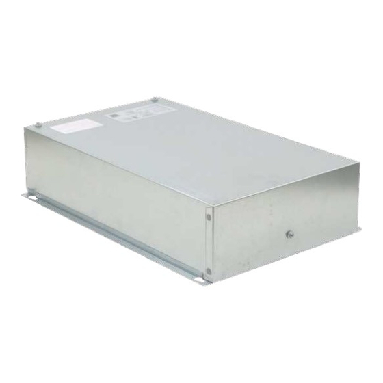
PAC-AH001-1 4. Specifications 4.1. AHU Controller Specifications Model PAC-AH001-1 Power Supply 208/230 VAC, 60 Hz, 1-Phase External Finish Galvanized Steel Plate Power Input 0.012 Current 0.055 Height 19.5 (496) Dimension Width in (mm) 12.8 (326) Depth 4.7 (119) Control Box Net Weight (without packaging) lbs (kg) 11.5 (5.2) IP class... -
Page 15: Outlines And Dimensions
PAC-AH001-1 5. Outlines and Dimensions 5.1. AHU Controller PAC-AH001-1 19.5 [496] 17.3 [119] [440] 19.5 [496] [114] © 2018 Mitsubishi Electric US, Inc. -
Page 16: Single Valve Lev Assembly
PAC-AH001-1 5.2. Single Valve LEV Assembly PAC-LEV24AC-1 16.4 [416] PAC-LEV48AC-1, PAC-LEV60AC-1 16.5 [419] Specifications are subject to change without notice. -
Page 17: Double Valve Lev Assembly
PAC-AH001-1 5.3. Double Valve LEV Assembly PAC-LEV96AC-1, PAC-LEV120AC-1 23.2 [590] [142] © 2018 Mitsubishi Electric US, Inc. -
Page 18: Wiring Diagram
PAC-AH001-1 6. Wiring Diagram F1 10A F2 10A ZNR02 ZNR01 DC280-340V RECTIFIER CIRCUIT Specifications are subject to change without notice. -
Page 19: Microprocessor Control
(COOL) Note: COOL operation mode must be set using City Multi controller © 2018 Mitsubishi Electric US, Inc. 2.) Thermo-regulating function (1) Thermo-regulating function (Function to prevent restarting for 3 minutes) When indoor units are connected to the PUHY/PURY/PQHY/PQRY series of outdoor units. - Page 20 PAC-AH001-1 Control Type Type 1 (For Temperature Control) Type 2 (For Capacity Control) (SWA-2) (SWA-3) Set point temperature = 5.625 X Ain Set point temperature = -5.625 X Ain + 40.775 [°F] + 100.4 [°F] [Ain = Input Temperature] [Ain = Input Temperature] Setting Temperature Setting Temperature Control...
-
Page 21: Thermo-Regulating Function
3) The operation mode is changed to mode other than COOL. 4) The operation is stopped. 7.1.3. Fan (1) Set the fan speed using the remote controller Type Fan speed notch 3 speeds [Low], [Med], [High] • [Auto] fan speed control is not available. © 2018 Mitsubishi Electric US, Inc. -
Page 22: Float Switch Control
PAC-AH001-1 VII Microprocessor Control ] 7.1.4. Float switch control In the air : Detected that the float switch is OFF for 15 seconds. Float SW 15sec. 15sec. 15sec. 1min.30sec. 1min.30sec. Drain pump In the water In the air In the water Error postponement abnormal... -
Page 23: Fan
[Low] 7.3. Fan Operation Control Mode Fan Operation (Available Control Modes) Return Air Control Discharge Air Control City Multi Controller ● ● Controller Type Type 1 ● ● Party Controls Type 2 ● ● © 2018 Mitsubishi Electric US, Inc. -
Page 24: How To Operate
PAC-AH001-1 7.3.1. How to operate 1. Press POWER ON/OFF button. 2. Press the operation MODE button to display FAN. 7.3.2. Fan (1) Set by remote controller Type Fan speed notch 3 speeds [Low], [Med], [High] • [Auto] fan speed control is not available. VII Microprocessor Control ] 7.3.3. -
Page 25: Heat Operation
Discharge Air Control: 46.4~82.4 °F [8~28 °C] Input Voltage 2.) Thermo-regulating function (1) Thermo-regulating function (Function to prevent restarting for 3 minutes) © 2018 Mitsubishi Electric US, Inc. When indoor units are connected to the PUHY/PURY/PQHY/PQRY series of outdoor units. -
Page 26: Thermo-Regulating Function
PAC-AH001-1 NOTE HEAT operation mode must be set using City Multi controller Heating Set-point Range with 3rd Party Controller • Discharge Air Control: 46.4~82.4 °F [8~28 °C] 7.4.2. Thermo-regulating function (1) Thermo-regulating function (Function to prevent restarting for 3 minutes) When indoor units are connected to the PUHY/PURY/PQHY/PQRY series of outdoor units. -
Page 27: Fan
When the thermo regulating function changes to OFF, the indoor fan operates according to SW1-8 and SW1-7. 2. Discharge Air Control When the thermo regulating function changes to OFF, the indoor fan speed does not change. (5) Heat defrosting mode The indoor fan stops. © 2018 Mitsubishi Electric US, Inc. -
Page 28: Float Switch Control
PAC-AH001-1 VII Microprocessor Control ] 7.4.4. Float switch control In the air : Detected that the float switch is OFF for 15 seconds. Float SW 15sec. 15sec. 15sec. 1min.30sec. 1min.30sec. In the water In the air In the water Error Drain pump abnormal postponement... -
Page 29: Initial Operation Mode
(2) COOL Mode -> HEAT Mode: Room temperature < Desired temperature - 3°F (continued over 3 min) 7.5.4. COOL mode (1) Same control as cool operation 7.5.5. HEAT mode (1) Same control as heat operation The value "3°F" is modifiable from 1.8°F to 9°F by maintenance tool. © 2018 Mitsubishi Electric US, Inc. -
Page 30: Heater Control
PAC-AH001-1 7.6. Heater Control 7.6. Heater Control Control Mode Heater Operation (Available Control Modes) Return Air Control Discharge Air Control ● 8.5 Electric Heater Control City Multi Controller Controller Type 1 Party Type Controls Type 2 *1 Heater operation only available when operating in Return Air Control using a City Multi Controller NOTE •... - Page 31 EH2 ON X min X min X min ① ① EH1 OFF (To -T ) < 0.9 °F [0.5°C] ⑥ X min ④ EH2 OFF ⑤ X min X min X min ④ ⑤ © 2018 Mitsubishi Electric US, Inc.
-
Page 32: Humidifier Control
PAC-AH001-1 7.7. Humidifier Control 13.5. Humidiier max 30 ft. Sequence of operation: Humidiier Control The humidistat closes CNF The fan starts on high 1. The humidistat closes CNF CN25 provides 12VDC to turn on the Humidifier (do not exceed 1 Watt draw per relay) 3. - Page 33 Heat operation & Thermo OFF High Heat operation & Thermo ON ─ ─ Except for heat operation RC Setting Factory Setting RC: Remote controller The fan continues to run for 30 seconds after the humidifier stops. © 2018 Mitsubishi Electric US, Inc.
-
Page 34: Troubleshooting
PAC-AH001-1 8. Troubleshooting 8.1. Check Methods 1. Component and check points (1) Thermistor • Return air thermistor (TH21) • Liquid pipe thermistor (TH22) • Gas pipe thermistor (TH23) • Discharge air thermistor (TH24) Rt: Thermistor Resistance [kΩ] t: Thermistor Measurement Temperature [°C] Disconnect the connector and measure the resistance between terminals with a tester. - Page 35 • The LEV is operated by a stepping motor, which operates by receiving a pulse signal from the indoor control board. • The LEV position changes in response to the pulse signal. Indoor control board and LEV connection © 2018 Mitsubishi Electric US, Inc.
- Page 36 PAC-AH001-1 (A) Brown (F) White (B) Red (G) Control board (C) Black (H) Connection (CN60, CN7V) (D) Green (I) Drive circuit (E) Yellow (J) Linear expansion valve Pulse signal output and valve operation Output pulse Phase number Φ1 Φ2 Φ3 Φ4 The output pulse changes in the following order: When the valve closes 1 ->...
- Page 37 Perform a visual check for disconnected connectors. Disconnect the connectors or con- Perform a visual check of lead wire color. connectors on tact failure the control board and perform a continuity test. © 2018 Mitsubishi Electric US, Inc. (4) Drain-up mechanism...
-
Page 38: Address Switch Setting
PAC-AH001-1 Symptom Checking Criteria Remedy Normally, the LEV is fully closed while the unit is in the FAN mode. If the valve is leaky, liquid pipe thermistor reading will be lower than normal. If it is significantly lower than the inlet temperature on the remote controller, valve closure failure is suspected. - Page 39 2. Address is set with a combination of SW12 (10's digit) and SW11 (1's digit). To set the address to "3," set SW12 to "0" and SW11 to "3." To set the address to "25," set SW 12 to "2" and SW 11 to "5." © 2018 Mitsubishi Electric US, Inc.
-
Page 40: Voltage Test Points
PAC-AH001-1 8.3. Voltage test points CN2A Fuse (AC 250V 6.3A) Power supply voltage (220 - 240VAC) CN2M CN2M For M-NET transmission cable connection (24 - 30VDC) CNXB2 Fan Forced ON Mode selection CN41 CN3A Capacity setting CN51 CN52 Mode selection Mode selection CN20 CN27 (CN24-2) -
Page 41: Dipswitch Setting
57 °F [14 °C] 59 °F [15 °C] Not Available Factory Setting in Gray Dip switch settings must be made while the unit is stopped. There is no need to power cycle the unit. © 2018 Mitsubishi Electric US, Inc. -
Page 42: Return Air Control (Factory Setting)
PAC-AH001-1 (3) SW4 - Function Setting Switch Switch Setting Function Position Position Model Code Model Code (Not Available) (Not Available) Not Available Not Available Control Method Control Method Discharge Air Control Return Air Control Discharge Air Control Return Air Control Selection Selection Not Available... - Page 43 Discharge Air Control Return Air Control Selection Not Available Not Available Factory Setting in Gray Dip switch settings must be made while the unit is stopped. There is no need to power cycle the unit. © 2018 Mitsubishi Electric US, Inc.
-
Page 44: Sw2 - Capacity Code Setting
PAC-AH001-1 8.4.3. SW2 – Capacity Code Setting Dip switch settings must be made while the unit is stopped. There is no need to power cycle the unit. Capacity Code Design Capacity Setting LEV Assembly Setting Range Cooling switches Model [Ton] [Btu/h] SW3-6 4,800-6,000... -
Page 45: Sw5 - Power Voltage Setting (Factory Setting)
SWC has no use. 7. SW11, SW12, SW14 - Address Setting (Factory Setting) (1) SW11, SW12 (Rotary switch) Factory Setting Address switch settings must be made while the unit is stopped and the remote controller is stopped. © 2018 Mitsubishi Electric US, Inc. -
Page 46: Sw11, Sw12, Sw14 - Address Setting (Factory Setting)
PAC-AH001-1 8.4.7. SW11, SW12, SW14 - Address Setting (Factory Setting) SW11, SW12 (Rotary switch) Factory Setting Address switch settings must be made while the unit is stopped and the remote controller is stopped. SW14 (Rotary switch) This switch is used when the unit connected to an R2 series of outdoor unit. Factory Setting Address switch settings must be made while the unit is stopped and the remote controller is stopped. - Page 47 Specifications are subject to change without notice.
- Page 48 Please be sure to put the contact address/telephone number on this manual before handing it to the customer. MITSUBISHI ELECTRIC US, INC. www.mitsubishielectric-usa.com Toll Free: 800-433-4822 MEUS DOC#MD-1624-K002 Ver02 February 2018 Specifications are subject to change without notice. © 2018 Mitsubishi Electric US, Inc.