Table of Contents
Advertisement
SIMATIC
C7-635 Control System
Manual
The following supplement is part of this documentation:
No.
Designation
1
Product information
This manual is part of the documentation
package with the order number:
6ES7635-1EA00-8BA0
This manual has the order number:
6ES7635-1AA00-8BA0
Edition 03/2004
A5E00155581-04
Siemens Controls
Drawing number
Edition
A5E00861679-01
07/2006
Preface, Contents
Document Guide
Product Overview
Installing and Wiring the C7-635
Special Features of the C7-635
Maintenance
Appendices
Technical Specifications
Index
1
2
3
4
5
A
Advertisement
Table of Contents

Related Manuals for Siemens SIMATIC C7-635


Summary of Contents for Siemens SIMATIC C7-635
- Page 1 The following supplement is part of this documentation: Designation Drawing number Edition Product information A5E00861679-01 07/2006 This manual is part of the documentation package with the order number: 6ES7635-1EA00-8BA0 This manual has the order number: 6ES7635-1AA00-8BA0 Edition 03/2004 A5E00155581-04 Siemens Controls...
- Page 2 Trademarks SIMATIC®, SIMATIC HMI® and SIMATIC NET® are registered trademarks of SIEMENS AG. Third parties using for their own purposes any other names in this document which refer to trademarks might infringe upon the rights of the trademark owners.
- Page 3 • SIMATIC Touch Panel TP170 B (C7-635 Touch) and Operator Panel OP170 B (C7-635 Key) Manuals providing detailed information on these individual components are included in this documentation package. These manuals are essential when working with the C7-635. Siemens Controls C7-635 Control System A5E00155581-04...
- Page 4 Preface The documentation package consists of seven manuals and an instruction list: Description of: C7-635 Control System • Installation and wiring • Operator input Manual • Technical Specifications of the C7-635 Touch Panel “TP170 A”, “TP170 B”, Provides information about: Operator Panel “OP170 B”...
- Page 5 Function block diagram (FBD) for S7-300/400 PLCs Reference manual Approbation For detailed information on approvals and standards, refer to Appendix A, Technical data. Standards The C7-635 meets the requirements and criteria of IEC 61131-2. Siemens Controls C7-635 Control System A5E00155581-04...
- Page 6 Additional Support If you have questions regarding the use of the products described in the manual and are unable to find an answer here, please contact your nearest Siemens representative. http://www.ad.siemens.com/automation/partner You will find a guide to the technical documentation offered for the individual SIMATIC Products and Systems here at: http://www.siemens.com/simatic–tech–doku–portal...
- Page 7 +86 10 64 74 74 74 Fax: +49 (180) 5050-223 mailto:simatic.hotline@sea.siemens.com mailto:adsupport.asia@siemens.com mailto:adsupport@siemens.com GMT: +8:00 GMT: –5:00 GMT: +1:00 The languages of the SIMATIC Hotlines and the authorization hotline are generally German and English. Siemens Controls C7-635 Control System A5E00155581-04...
- Page 8 Preface Service & Support on the Internet In addition to our documentation, we offer our Know-how online on the internet at: http://www.siemens.com/automation/service&support where you will find the following: • The newsletter, which constantly provides you with up-to-date information on your products.
-
Page 9: Table Of Contents
............. Index-1 Siemens Controls C7-635 Control System... - Page 10 Contents Figure C7-635 Touch ........... C7-635 Key .
-
Page 11: Document Guide
System Settings Touch Panel TP170 A, TP170 B, Operator Panel OP170 B, Chapter 9 Maintenance Chapter 5 Technological Functions S7-300 Automation System CPU 31xC Technological Functions Technical Specifications Appendix A Scope of Functions Appendix A Siemens Controls C7-635 Control System A5E00155581-04... - Page 12 Document Guide C7-635 Control System A5E00155581-04...
-
Page 13: Product Overview
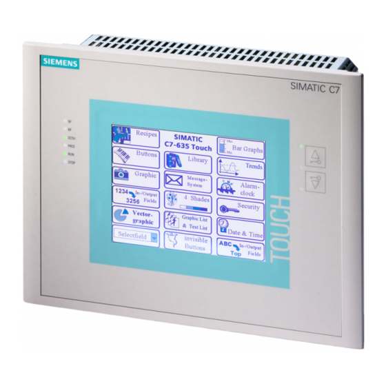
Product Overview Configuration and Structure Figure 2-1 C7-635 Touch Siemens Controls C7-635 Control System A5E00155581-04... -
Page 14: C7-635 Key
Product Overview Figure 2-2 C7-635 Key C7-635 Control System A5E00155581-04... - Page 15 Product Overview Components The SIMATIC C7-635 consists of the following components: • SIMATIC S7 314C-2 DP CPU • SIMATIC touch panel TP170 B or operator panel OP170 B Interfaces SIMATIC C7-635 interfaces: • An interface for connecting up to four S7-300 modules via the S7-300 I/O bus •...
-
Page 16: Components And Interfaces Of The C7-635
Product Overview C7-635 C7-PLC C7-TP/OP Card CPU memory TP/OP memory C7-CPU C7-TP/OP Integrated RS232 interface interface interface S7-300 I/O bus expansion STEP 7 ProTool Figure 2-3 Components and interfaces of the C7-635 Plug-In Modules on the S7-300 I/O Bus Note I/O expansions can be interconnected via the S7 300 I/O bus without IM interface module using the following accessories: •... - Page 17 Product Overview Interplay of CPU and TP/OP The individual components integrated in the SIMATIC C7-635 correspond to the components that can also be used for modular configurations consisting of CPU-314C-2DP, TP170 B, and OP170 B. The basic mode of operation is also similar to operation of a configuration with standard modules from the programmable controller and TP/OP family;...
- Page 18 Product Overview The user program controlling the process runs on the C7-635. The following functional units determine the mode of operation of the C7-635: • Loading memory The loading memory is located on the Micro Memory Card (MMC) and contains the user program.
- Page 19 • Curves • Interrupt timer • Recipe management • Backup of recipe data and configurations on optional memory card (CF card) You will find a complete overview of the scope of functions in Appendix A. Siemens Controls C7-635 Control System A5E00155581-04...
-
Page 20: C7-635 Components And Accessories
Product Overview C7-635 Components and Accessories Components The following components are supplied with the C7-635: • 1 C7-635 Touch (6ES7635-2EB01-0AE3) with sealing or 1 C7-635 Key (6ES7635-2EC01-0AE3) with sealing • 1 grounding busbar, including two mounting screws and six shielding terminals •... - Page 21 6ES7635-0AA00-6EA0 • Protective film for the C7-635 display 6AV6574-1AD00-4AX0 • Paper documentation C7-635 control system Consisting of: – C7-635 manual in the following languages: German: 6ES7635-1AA00-8AA0 English: 6ES7635-1AA00-8BA0 French: 6ES7635-1AA00-8CA0 Spanish: 6ES7635-1AA00-8DA0 Italian: 6ES7635-1AA00-8EA0 Siemens Controls C7-635 Control System A5E00155581-04...
- Page 22 Product Overview • Paper documentation C7-635 control systemdocumentation package Consisting of: – C7-635 manual – Manuals for CPU 314C-2 DP – Touch Panel TP170 A TP170 B, Operator Panel OP170 Bmanual – Communication for Windows-Based Systems manual) in the following languages: German: 6ES7635-1EA00-8AA0 English:...
-
Page 23: Installing And Wiring The C7-635
Pack 2, directory Utilities) or can be obtained from the Internet. With it, you can design and print out system-specific labeling strips easily. Internet address: www.siemens.com/automation/service&support The file “SLIDE635.DOC” with the labeling strips can be obtained by selecting Product Support > Automation Systems > SIMATIC Industrial Automation Systems >... -
Page 24: Inserting Labeling Strips For C7-635 Key
Installing and Wiring the C7-635 The strip is inserted as follows: Step Action Place the device with the front plate facing downward. Remove any labeling strips that have been previously inserted. With the labeling pointing downward, insert the new labeled strips into the slits on the front panel (use tweezers, if necessary). -
Page 25: Mechanical Installation
C7-635 Touch, 8 mounting supports; for the C7-635 Key, 10 mounting supports) into the intended recesses in the C7 635 housing. Figure 3-2 provides an example of the mechanical fastening of the C7-635 Touch. Siemens Controls C7-635 Control System A5E00155581-04... -
Page 26: Mechanically Fastening The C7-635 Touch
Installing and Wiring the C7-635 Table 3-1 Mechanical Installation, continued Step Action Using a screwdriver, tighten the C7 635 evenly and crosswise from behind in the control cabinet door until the front panel of the C7-635 rests on the Á control cabinet door . -
Page 27: Dimension Drawings For The C7-635 Key (Measurements In Mm)
Installing and Wiring the C7-635 273,8 +1.0 Cutout in control cabinet door +1.0 Figure 3-4 Dimension Drawings for the C7-635 Key (Measurements in mm) Siemens Controls C7-635 Control System A5E00155581-04... -
Page 28: Dimension Drawings For The C7-635 Touch (Measurements In Mm)
Installing and Wiring the C7-635 Figure 3-5 Dimension Drawings for the C7-635 Touch (Measurements in mm) C7-635 Control System A5E00155581-04... - Page 29 Installing and Wiring the C7-635 Figure 3-6 Dimension Drawings for the C7-635 Touch (Measurements in mm) Siemens Controls C7-635 Control System A5E00155581-04...
-
Page 30: Dimension Drawings For The C7-635 Key (Measurements In Mm)
Installing and Wiring the C7-635 Siemens Figure 3-7 Dimension Drawings for the C7-635 Key (Measurements in mm) C7-635 Control System A5E00155581-04... -
Page 31: Dimension Drawings For The C7-635 Key (Measurements In Mm)
Installing and Wiring the C7-635 Figure 3-8 Dimension Drawings for the C7-635 Key (Measurements in mm) Siemens Controls C7-635 Control System A5E00155581-04... -
Page 32: Locating The C7-635 In A Mechanical Environment
Installing and Wiring the C7-635 Locating the C7-635 in a Mechanical Environment Locating the C7-635 When installing a C7-635, pay attention to the following: • The sheet thickness of a control cabinet door can be 2 to 4 mm. You must ensure that the gasket seals tightly around the entire device. -
Page 33: Setting Up The Electrical Configuration And Connector Pin Assignment
X 10 in front DI 16 X 11 in front AI4 + 1 PT100 X 13 in back DO 16 X 12 in back Figure 3-11 C7-635 Touch with Connectors and Sockets, Front View Siemens Controls C7-635 Control System 3-11 A5E00155581-04... -
Page 34: C7-635 With Connectors And Sockets, Back View
Installing and Wiring the C7-635 Compact Micro SIMATIC C7 Flash Memory Card Card of of the CPU the TP 5 VDC Programming FRCE device Backplane connection STOP bus (I/O (MPI) bus) X 5 in X 2 in front front PROFIBUS/ RS 232 X 3 in back X 4 in... -
Page 35: C7-635 Layout Of Connector Pin Assignment
Figure 3-13 C7-635 Layout of Connector Pin Assignment Micro Memory Card (MMC) of the CPU X 7 Programming device PROFIBUS/DP connection (MPI) Supply Connector Figure 3-14 C7-635 with Connectors and Sockets, Side View Siemens Controls C7-635 Control System 3-13 A5E00155581-04... - Page 36 Installing and Wiring the C7-635 Supply connector X1 Table 3-2 Supply Connector X1 Signal Description Name Authorization input (for example, for external switch) Authorization input (for example, for external switch) Ground 24 V Supply voltage 24 VDC Programming Device Connection (MPI) 2 Table 3-3 Programming Device Connection (MPI) 2 Pin Name...
-
Page 37: C7-635 With Connectors And Sockets, Bottom View
Clear to send Not connected DO 16 X 12 AI4 + 1 PT100 X 13 Supply I/O DI 8 X 10 DI 16 X 11 Figure 3-15 C7-635 with Connectors and Sockets, Bottom View Siemens Controls C7-635 Control System 3-15 A5E00155581-04... - Page 38 Installing and Wiring the C7-635 I/O connector X10 Table 3-6 Connector Pin Assignment I/O Connector X10 Pin Name Signal Description DI+2.0 Digital input 16 DI+2.1 Digital input 17 DI+2.2 Digital input 18 DI+2.3 Digital input 19 DI+2.4 Digital input 20 DI+2.5 Digital input 21 DI+2.6...
- Page 39 Digital input 12 Channel – – 0: Latch DI+1.5 Digital input 13 Channel – – 1: Latch DI+1.6 Digital input 14 Channel – – 2: Latch DI+1.7 Digital input 15 Channel – 3: Latch Siemens Controls C7-635 Control System 3-17 A5E00155581-04...
- Page 40 Installing and Wiring the C7-635 I/O Connector X 12 For the technological functions, the meaning of the outputs is described in the columns “Counting”, “Frequency Measuring”, “Pulse Width Modulation”, “Analog Positioning”, and Digital Positioning”. Table 3-8 Connector Pin Assignments I/O Connector X12 Signal Description Counting...
- Page 41 Analog reference potential channel 3 Analog ground Analog ground PT100_OUT PT100_IN Compact Flash Card of the TP RS 232 Backplane bus (I/O bus) X 5 Analog output AO2 Figure 3-16 C7-635 with Connectors and Sockets, Side View Siemens Controls C7-635 Control System 3-19 A5E00155581-04...
- Page 42 Installing and Wiring the C7-635 Analog output X14 For the technological functions, the meaning of the outputs is described in the column “Analog Positioning”. Table 3-10 Connector Pin Assignments Analog Output X 14 Pin Name Signal Description Analog Positioning AO0_U Analog voltage output Voltage output channel 0...
- Page 43 C7 ⎯ printer ST80.1 IM361 IM361 cable C7 ⎯ Additional I/O (S7-300) C7-635 I/O connections Connectors for C7-635 I/O 16-pin C7 ⎯ External sensing elements/ 6-pin actuators 4-pin Cable cross section 0.2 to 2.5 Siemens Controls C7-635 Control System 3-21 A5E00155581-04...
-
Page 44: Guidelines For Fail-Safe Construction
– Bus cables – I/O device cables • Standard cables from Siemens comply with these requirements. • All plug connections must be screwed or clamped into place. • Signal lines must not be laid parallel to heavy current lines. A separate cable channel must be used that is separated from heavy current lines by at least 50 cm. - Page 45 (surface grounding with building construction, sheathing). Functional Ground Connect the functional ground (see Figure 3-17) to the cabinet ground with a cable lug and a cable with a minimum cross section of 4 mm Siemens Controls C7-635 Control System 3-23 A5E00155581-04...
-
Page 46: Connecting Shielded Cables
Installing and Wiring the C7-635 Connecting Shielded Cables Overview This section describes how to connect the shield of shielded signal lines to the ground. A grounding terminal is used to connect the shield directly to the ground of the C7-635. Procedure Proceed as follows to install the grounding terminal supplied with the C7-635 and the shield terminals:... -
Page 47: Coding Connector Parts To Prevent Incorrect Usage
If a coding profile and coding carrier do not face one another, the connector part can be inserted without difficulty. ❷ ❶ ➁ ➀ Figure 3-18 Preventing Incorrect Usage of Connectors Siemens Controls C7-635 Control System 3-25 A5E00155581-04... - Page 48 Installing and Wiring the C7-635 C7-635 Control System 3-26 A5E00155581-04...
-
Page 49: Special Features Of The C7-635
• All integrated I/O inputs have a common reference ground Deviations from TP170 /OP170 B • RS 485 interface (MPI) can not be switched to RS 422 interface • No second RS 232 interface • No DP interface to TP/OP Siemens Controls C7-635 Control System A5E00155581-04... -
Page 50: Operating Mode Selection
Special Features of the C7-635 Operating Mode Selection Status and error LEDs Operating mode keys with touch LEDs Figure 4-1 C7-635 Touch Changing the C7-CPU Operating Mode The figure above uses the C7-635 Touch as an example. The function and position of the operating mode keys and the status and error LEDs are the same for the C7-635 Key. - Page 51 Can be transmitted to the C7-CPU and changed there (programming device/PC → C7). Note: STOP mode is only valid for the C7-CPU. It does not apply to the C7-TP/OP. It is always possible to continue working with the C7-TP/OP. Siemens Controls C7-635 Control System A5E00155581-04...
- Page 52 Special Features of the C7-635 Table 4-1 Operating Mode Keys, continued Operating Description/Procedure Mode MRES General reset Performing a general reset of the C7-CPU (clearing the memory and reloading the user program from the MMC) requires a special operating mode key procedure: 1.
-
Page 53: Status And Error Displays Of The C7-635
If you insertan IM-360 interface module, you can use it to connect additional modules. You will find a description of how to install S7-300 modules in the S7-300, CPU 31xC and CPU 31x: Hardware and Installation manual. Siemens Controls C7-635 Control System A5E00155581-04... - Page 54 Special Features of the C7-635 Connecting Additional S7-300 Modules Directly on the Device In the figures below, the C7-635 Touch is used as an example. The installation steps are the same for the C7-635 Key. 2-Module I/O set As a prerequisite, you must have the “2-module I/O set” accessory specifically for the C7-635.
- Page 55 4. Mount the modules on the S7 DIN rail (190 mm). C7-635 S7 DIN rail S7-300 modules Figure 4-3 Connecting Additional S7-300 Modules Directly on the Device Using the 2-Module I/O Set Siemens Controls C7-635 Control System A5E00155581-04...
- Page 56 Special Features of the C7-635 Connecting Additional S7-300 Modules at a Distance of Up to 1.5 m As a prerequisite, you must have the “1.5 m cable” accessory specifically for the C7-635 and a standard DIN rail. Use the following procedure to connect the additional modules: 1.
-
Page 57: Status Display Of The Digital Onboard I/O
• 0 DI/DO reset Á Pin Name DI/DO Note The values of the DI/DO are read in and displayed in the time configured with ProTool. Changes made between these two occurrences are not displayed. Siemens Controls C7-635 Control System A5E00155581-04... - Page 58 Special Features of the C7-635 C7-635 Control System 4-10 A5E00155581-04...
-
Page 59: Maintenance
Spray the cleaning solution onto the cloth, rather than directly onto the monitor. Note If you use a harsh solvent or scouring solution, the keyboard can rub off or the touch screen can be damaged. Siemens Controls C7-635 Control System A5E00155581-04... -
Page 60: Replacing The C7-635
Maintenance Replacing the C7-635 Introduction A C7-635 is not designed for onsite repair. Therefore, a defective C7-635 must be replaced. To save the configuration of the TP/OP, you should have a Compact Flash Card (CF Card). You should make a backup of the configuration on the CF card as soon as you have finished commissioning the device, so that you can restore the configuration if the device becomes defective. - Page 61 Switch off the power supply. Loosen the cables from the shielding terminals and remove all connectors. Remove the MMC. Loosen the mounting supports with a screwdriver and remove the device from the control cabinet. Siemens Controls C7-635 Control System A5E00155581-04...
- Page 62 Maintenance Installation Step Action Complete the mechanical installation as described in Section 3.2. Be sure to observe the relevant notes. Insert the MMC. Insert the cables and press the bare cables into the shielding terminals, as described in Section 3.6. Switch on the power supply.
-
Page 63: Technical Specifications
2 A for 70 ms 2 A for 70 ms Power losses 14 W 14 W Ungrounded configuration Not possible Software C7-635 Touch C7-635 Key TP/OP operating system platform MS Windows CE MS Windows CE Siemens Controls C7-635 Control System A5E00155581-04... - Page 64 Technical Specifications Safety C7-635 Touch C7-635 Key Standard references DIN EN 61131-2 corresponds to IEC 61131-2 Protection against ingress of solid foreign bodies and water IP 65 in accordance with IEC IP 65 in accordance with IEC • Front panel 60529, NEMA 4X 60529, NEMA 4X •...
-
Page 65: Technical Specifications For Tp/Op
Operational Number messages Display Message line, message window/ message page, message display View all pending messages Message page/message display Length of message text per 70 characters line Process values in message text Edit message Siemens Controls C7-635 Control System A5E00155581-04... - Page 66 Technical Specifications Table A-2 Functional Scope of TP/OP, continued Function C7-635 Touch (TP) C7-635 Key (OP) Error messages Number Display Message line/ Message Message window/ window/message Message page/ page/ Message display message display Display type First/last, selectable Display all pending messages inmessage page/message display Length of message text per 70 characters...
- Page 67 Recipe display Operator prompting • Dynamic attributes • Show/hide objects • Help text • TAB sequence • Pictograms for softkeys • LEDs in function keys Permanent window Limit-value Inputs/outputs monitoring Conversion Inputs/outputs functions Variables Number Siemens Controls C7-635 Control System A5E00155581-04...
- Page 68 Technical Specifications Table A-2 Functional Scope of TP/OP, continued Function C7-635 Touch (TP) C7-635 Key (OP) Help text Lines/characters 7/35 For messages For screens For screen objects • Input field • Select field • Button • Status button • Switch •...
-
Page 69: Technical Specifications For Cpu
Unlimited (limited only by user memory) S7 timers • Retentivity Adjustable • Default No retentivity • Timing range 10 ms to 9,990 s IEC timers • Type • Number Unlimited (limited only by user memory) Siemens Controls C7-635 Control System A5E00155581-04... - Page 70 Technical Specifications Data Areas and their Retentive Characteristics Total retentive data area (including memory bits; timers; counters) Bit memories 256 bytes • Retentivity Adjustable • Retentivity preset MB 0 to MB 15 Clock memories 8 (1 memory byte) Data blocks Maximum 511 •...
- Page 71 Number of stations that can log in Maximum 12 for message functions (depends on the number of connections configured for PG/OP and (for example, OS) S7 basic communication) Process diagnostic messages • Simultaneously active alarm Maximum 40 S-blocks Siemens Controls C7-635 Control System A5E00155581-04...
- Page 72 Technical Specifications Testing and Commissioning Functions Status/control variable • Variable Inputs, outputs, flags, DBs, timers, counters • Number of variables Maximum 30 Of total, number of status Maximum 30 variables Of total, number of control Maximum 14 variables Force • Variables Inputs, outputs •...
- Page 73 • Programming device/OP communication • Routing • Global data communication • S7 standard communication • S7 communication • Equidistance • SYNC/FREEZE • Activate/deactivate DP slaves Yes • Transmission rates Up to 12 Mbaud Siemens Controls C7-635 Control System A-11 A5E00155581-04...
- Page 74 Technical Specifications PROFIBUS-DP • Number of DP slaves per Maximum 32; station • Address area Maximum 1 Kbyte I / 1 Kbyte O • Useful data per DP slave Maximum 244 bytes I / 244 bytes O DP slave Number of connections Services •...
- Page 75 4 channels in total, Frequency meters, Frequency meter up to 60 kHz, maximum, Pulse outputs (pulse width Pulse outputs up to 2.5 kHz, maximum modulation) Controlled positioning 1 channel Integrated SFB ”controlling” PID controller Siemens Controls C7-635 Control System A-13 A5E00155581-04...
-
Page 76: Technical Specifications For Integrated I/O
Technical Specifications Technical Specifications for Integrated I/O igital inputs Number Number of inputs • inputs usable for technological functions Cable Length (for Standard DI /Technological Functions) • Unshielded Maximum 600 m / No • Shielded Maximum 1000 m / Maximum 50 m Voltage, Currents, Potentials Rated load current L+ 24V DC... - Page 77 Minimum pulse width / 8 μs minimum pulse interval at maximum count frequency Input characteristic According to IEC 1131, Type 1 Connection of 2-wire BEROs Possible • Permissible quiescent current Maximum 1.5 mA Siemens Controls C7-635 Control System A-15 A5E00155581-04...
- Page 78 Technical Specifications Digital outputs Note Technological functions utilize fast digital outputs. These outputs must only be connected to resistive loads. Number Number of outputs • Of total, number of fast outputs Cable length • Unshielded Maximum 600 m • Shielded Maximum 1,000 m (109 yd.) Voltage, Currents, Potentials Rated load current L+...
- Page 79 Maximum 100 Hz • Fast outputs with resistive Maximum 2.5 kHz load Inductive breaking voltage limited (L+) – 48 V, typically internally to Short-circuit protected output Yes, electronic • Response threshold 1 A, typically Siemens Controls C7-635 Control System A-17 A5E00155581-04...
- Page 80 Technical Specifications Analog inputs Number Number of inputs • Current / voltage input 4 channels • Resistance input 1 channel Cable length • Shielded Maximum 100 m (109 yd.) Voltage, Currents, Potentials Resistance input • No-load voltage 2.5 V, typically •...
- Page 81 When using the technological functions, see CPU 31xC Technological Functions manual • Diagnostic functions No diagnostics when operated as standard I/O • When using the technological functions, see CPU 31x Technological Functions manual Siemens Controls C7-635 Control System A-19 A5E00155581-04...
- Page 82 Technical Specifications Encoder Selection Data Input ranges (rated value)/input resistance • Voltage +/– 10 V/100 k Ω 0 V to 10 V/100 kΩ • Current +/– 20 mA/50 Ω 0 mA to 20 mA/50 Ω 4 mA to 20 mA/50 Ω •...
- Page 83 +/– 1% Basic error limits (operational limit at 25°C, relative to output range ) • Voltage/current +/– 0.7% Temperature error (relative to +/–0.01 %/K output range) Linearity error (relative to output +/–0.15% range) Siemens Controls C7-635 Control System A-21 A5E00155581-04...
- Page 84 Technical Specifications Status, Interrupts, Diagnostics • Interrupts No interrupts when operated as standard I/O • When using the technological functions, see CPU 31xC Technological Functions manual • Diagnostic functions No diagnostics when operated as standard I/O • When using the technological functions, see CPU 31xC Technological Functions manual Actuator Selection Data Output range (rated values)
-
Page 85: Notes On Power Supply
• UL 508 (Industrial Control Equipment) CSA approval Canadian Standards Association to • C22.2 No. 142 (Process Control Equipment) Underwriters Laboratories Inc. to S UL 508 (Industrial Control Equipment) S CSA C22.2 No. 142 (Process Control Equipment) Siemens Controls C7-635 Control System A-23 A5E00155581-04... - Page 86 Technical Specifications Underwriters Laboratories Inc. to S UL 508 (Industrial Control Equipment) S CSA C22.2 No. 142 (Process Control Equipment) HAZ. LOC. S UL 1604 (Hazardous Location) S CSA-213 (Hazardous Location) APPROVED for use in Class I, Division 2, Group A, B, C, D Tx; Class I, Zone 2, Group IIC Tx FM Approval FM standards 3611, 3600, and 3810 APPROVED for use in Class I,...
-
Page 87: Notes On Ce Marking
The EC declarations of conformity and their associated documentation are available to the proper authorities in accordance with the above-mentioned EC Guideline, Article 10 (1) at the following address: Siemens AG Automation and Drives Division A&D AS RD 42 P.O. Box 1963... -
Page 88: Notes For Machine Manufacturers
Technical Specifications Notes for Machine Manufacturers Introduction The SIMATIC automation system is not a machine in the sense of the EC guideline “Machinery”. Consequently, no declaration of conformity exists with regard to the EC guideline 89/392/EEC “Machinery”. EC Guideline 89/392/EEC ”Machinery” EC guideline 89/392/EEC “Machinery”... -
Page 89: Index
CSA, approval, A-23 Key-LEDs, 4-2 Keyboard, C7-635, 3-11, 3-12, 3-13, 3-15, 3-19 Degree of protection IP65, 3-3 Deviations from CPU314C-2 DP, 4-1 Deviations from TP 170 B, 4-1 Dewing, 3-3 Labeling strips, 3-1 Siemens Controls C7-635 Control System Index-1 A5E00155581-04... - Page 90 Index Machinery, with SIMATIC, A-26 Replacing the C7-635, 5-2 Maintenance, 5-1 Restore, 5-3 Manufacturers of machines, A-26 RUN, 4-3, 4-5 Marine, approval, A-24 Mechanical installation, 3-3 Minimum distance, C7, 3-10 Mounting depth, A-1 S7-300 modules, 4-5 2-module I/O set, A-1 SF, 4-5 4-module I/O set, A-1 Shielded cables, 3-24...
- Page 91 Non--retentive data blocks and code blocks can be loaded to the maximum limit of the working memory. Retentive data blocks can be loaded to the maximum retentive limit of the working memory (see the following table). Copyright Siemens AG 2006 Siemens Aktiengesellschaft A5E00861679-01 Siemens Controls...
- Page 92 Product Information A5E00861679-01...