Table of Contents
Advertisement
Quick Links
Advertisement
Table of Contents

Related Manuals for Fujitsu MB91F465XA


Summary of Contents for Fujitsu MB91F465XA
- Page 1 The following document contains information on Cypress products.
- Page 2 Colophon The products described in this document are designed, developed and manufactured as contemplated for general use, including without limitation, ordinary industrial use, general office use, personal use, and household use, but are not designed, developed and manufactured as contemplated (1) for any use that includes fatal risks or dangers that, unless extremely high safety is secured, could have a serious effect to the public, and could lead directly to death, personal injury, severe physical damage or other loss (i.e., nuclear reaction control in nuclear facility, aircraft flight control, air traffic control, mass transport control, medical life support system, missile launch control in weapon system), or (2) for any use where...
- Page 3 Fujitsu Microelectronics Europe MCU-AN-300015-E-V11 Application Note FR FAMILY 32-BIT MICROCONTROLLER MB91F465XA MB91F465XA EMULATION APPLICATION NOTE...
-
Page 4: Revision History
MB91F465XA EMULATION Revision History Revision History Date Issue V1.0 MSt 2007-04-24 Initial Version V1.1 MSt 2007-06-26 Further description added, typos corrected Figure 2-5 added This document contains 40 pages. MCU-AN-300015-E-V11 - 2 - © Fujitsu Microelectronics Europe GmbH... -
Page 5: Warranty And Disclaimer
Product or parts thereof, if the Product is returned to Fujitsu Microelectronics Europe GmbH in original packing and without further defects resulting from the customer´s use or the transport. -
Page 6: Table Of Contents
CONTENTS .......................... 4 1 INTRODUCTION......................6 2 HARDWARE SETUP ....................... 7 Required parts......................7 Installation ....................... 8 3 DIFFERENCES BETWEEN MB91F465XA AND EMULATION SYSTEM ...... 12 Overview about differences ................... 12 Details of differences..................... 13 3.2.1 Maximum operating frequency..............13 3.2.2... - Page 7 MB91F465XA EMULATION Contents 5.2.2 Vectors.c file .................... 37 Related Documentation ..................39 Figures ........................40 Tables ........................40 © Fujitsu Microelectronics Europe GmbH - 5 - MCU-AN-300015-E-V11...
-
Page 8: Introduction
Chapter 1 Introduction 1 Introduction This application note describes the emulation system for MB91F465XA series. The current emulation system is based on EVA device MB91V460A, which does not include a FlexRay interface. For that reason the FlexRay interface is emulated by MB88121B series stand alone FlexRay communication controller. -
Page 9: Hardware Setup
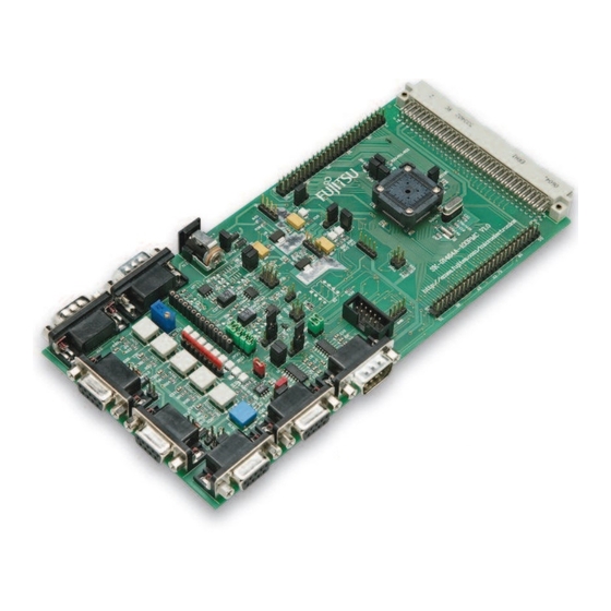
Socket adapter board 6. NQPack100SD-ND: Socket for package FPT-100P-M20 (Tokyo Eletech Corp. www.tetc.co.jp/e_tet.htm) On the target system a NQPack100SD-ND socket is required enabling connection to EMA- MB91F465X-NLS-100M20 board. Figure 2-1: Hardware Parts © Fujitsu Microelectronics Europe GmbH - 7 - MCU-AN-300015-E-V11... -
Page 10: Installation
Fasten the four screws using the screw driver delivered in the package. Pin 1 Figure 2-2: EMA-MB91F465X-NLS-100M20 at target system Note: Remove the Flash chip from the socket before connecting the socket adapter board to the socket! MCU-AN-300015-E-V11 - 8 - © Fujitsu Microelectronics Europe GmbH... - Page 11 MB91F465XA EMULATION Chapter 2 Hardware Setup 2. Plug the EMA-MB91V460A-00x board onto the EMA-MB91F465XA-NLS-100M20 board. The placement of the four connectors allows one position, only. Figure 2-3: EMA-MB91V460-00x on top of EMA-MB91F465X-NLS-100M20 3. The EMA-MB91V460A-100 extension board must be plugged into the two connectors at top of the EMA-MB91V460A-00x board.
- Page 12 4. Connect the MB2198-01 DSU cable to the MB2198-01 Emulator and to the EMA- 91V460A-00x board. Figure 2-6: MB2198-10 connected to MB2198-01 and EMA-MB91V460A-00x 5. Plug in the power supply of MB2198-01, EMA-MB91V460A-00x and the target system into the according plugs. MCU-AN-300015-E-V11 - 10 - © Fujitsu Microelectronics Europe GmbH...
- Page 13 To power down the system use the inverse order: 1. Target system 2. Adapter board EMA-MB91V460A-00x 3. Emulator MB2198-01 Note: When using the Fujitsu SK-91465X-100PMC evaluation board, the polarity of power supply is contrary to that of the EMA- MB91V460A-00x! © Fujitsu Microelectronics Europe GmbH - 11 -...
-
Page 14: Differences Between Mb91F465Xa And Emulation System
MB91F465XA EMULATION Chapter 3 Differences between MB91F465XA and Emulation System 3 Differences between MB91F465XA and Emulation System The chapter describes the differences between the emulation system and MB91F465XA series. 3.1 Overview about differences Emulation system Feature MB91F465XA series (MB91V460A + MB88121B) -
Page 15: Details Of Differences
3.2.1 Maximum operating frequency The maximum operating frequency of the emulation device MB91V460A is 80MHz. Do not set higher PLL frequencies! The MB91F465XA series has a maximum operating frequency of 100MHz. By using the Emulator take care that the PLL frequency should not exceed 80MHz. The PLL options can be set in the file start91460.asm (See Chapter 4.7.1 Clock Selection in... -
Page 16: E-Ray Register Start Address
Fujitsu provides two different header files for them. 1. mb91465x.h: for MB91F465XA series 2. mb91465x_emulation.h: for emulation system (MB91V460A + MB88121B) For further details refer to MB91460A series Hardware Manual and MB91F465XA series Datasheet. 3.2.4 E-Ray IP version The MB91F465XA is using E-Ray IP version 1.0 The MB88121B is using E-Ray IP version 1.0RC1... -
Page 17: E-Ray Interrupts
The FlexRay communication controller can be configured to request interrupts to MCU for different occurrence (See E-Ray User’s Manual). MB91F465XA: In MB91F465XA series four E-Ray interrupt sources are assigned to four interrupt vector numbers: • E-Ray interrupt line0: number 84 •... -
Page 18: Dma
E-Ray interrupt line1 is connected to external interrupt 13 (number 29) • E-Ray interrupt timer 0 and timer 1 are connected to external interrupt 11 (number The template project of MB91F465XA series contains the file vector.c, where the interrupt vector table can be specified. 3.2.10 DMA To speed-up the data transfer from output buffer or to input buffer, it is possible to launch a DMA transfer. -
Page 19: Softune Workbench
4.2 Template Workspace for MB91F465XA series In order to allow a quick and smooth project start-up Fujitsu Microelectronics Europe supplies a template project as a reference. The easiest way to start a new project is to make a copy of the template project and use this copy as a start-up. The template includes the latest start91460.asm file, MCU header file (mb91465x.h and mb91465x_emulator.h), IRQ... -
Page 20: A Muster Of The Macro Switch Is
The interrupt vector table and ICR registers in file vector.c are set according to the switch selection. The ICR registers define the interrupt level for the corresponding entry of the interrupt vector table (See file vector.c in Appendix). MCU-AN-300015-E-V11 - 18 - © Fujitsu Microelectronics Europe GmbH... -
Page 21: Use Configuration Emulator
Always check the memory map of the linker settings and ensure that this memory map is suitable for the application and target system in use. Additionally the *.mp1 file should be checked to ensure correct settings. © Fujitsu Microelectronics Europe GmbH - 19 - MCU-AN-300015-E-V11... - Page 22 Chapter 4 Softune Workbench Figure 4-2: Open Softune Workbench Linker mapping file Check linker mapping list in the*.mp1 file by right-click on “91460_template_91f465X.abs”, Open List File, *.mp1. Figure 4-3: Softune Workbench Linker Mapping MCU-AN-300015-E-V11 - 20 - © Fujitsu Microelectronics Europe GmbH...
- Page 23 Start Softune Emulator Debugger via the “Debug” Command Figure 4-4: Start Softune Workbench Emulator Debugger There are three possible connections between MB2198-01 Emulator and PC: COM1: MB2198-01-COM1.sup LAN: MB2198-01-LAN.sup USB: MB2198-01-USB.sup Select the suitable interface. © Fujitsu Microelectronics Europe GmbH - 21 - MCU-AN-300015-E-V11...
- Page 24 If the customize buttons are not visible, activate them via “View -> Customise bar -> View” Figure 4-6: View customize bar After the project is built and debugged successfully switch to the active configuration STANDALONE MCU-AN-300015-E-V11 - 22 - © Fujitsu Microelectronics Europe GmbH...
-
Page 25: Use Configuration Standalone
4.2.2 Use configuration STANDALONE Remove the emulation system and restore the Flash chip into the socket. The macro switch “Emulator” is set to “0”. The header-file and interrupt vector table for MB91F465XA series are included. Recompile the project. With the Flash programming utility (e.g. Fujitsu Flashprogrammer) program the generated mhx file (Motorola S-Record, located in sub-folder \STANDALONE\ABS\*.mhx) into the... -
Page 26: Appendix
Interrupt Line Enable 0x0000.0000 0x0044 Timer 0 Configuration 0x0000.0000 0x0048 Timer 1 Configuration 0x0000.0000 0x004C STPW1 Stop Watch Register 1 0x0000.0000 0x0050 STPW2 Stop Watch Register 2 0x0000.0000 0x0054 – Reserved 0x0000.0000 0x007C MCU-AN-300015-E-V11 - 24 - © Fujitsu Microelectronics Europe GmbH... - Page 27 0x0118 Rate Correction Value 0x0000.0000 0x011C Offset Correction Value 0x0000.0000 0x0120 Sync Frame Status 0x0000.0000 0x0124 SWNIT Symbol Window and NIT Status 0x0000.0000 0x0128 Aggregated Channel Status 0x0000.0000 0x012C Reserved 0x0000.0000 © Fujitsu Microelectronics Europe GmbH - 25 - MCU-AN-300015-E-V11...
- Page 28 New Data 4 0x0000.0000 Message Buffer Status Changed 0x0340 MBSC1 0x0000.0000 Message Buffer Status Changed 0x0344 MBSC2 0x0000.0000 Message Buffer Status Changed 0x0348 MBSC3 0x0000.0000 Message Buffer Status Changed 0x034C MBSC4 0x0000.0000 MCU-AN-300015-E-V11 - 26 - © Fujitsu Microelectronics Europe GmbH...
- Page 29 Read Header Section 3 0x0000.0000 0x071C Message Buffer Status 0x0000.0000 Output Buffer Command 0x0710 OBCM 0x0000.0000 Register Output Buffer Command 0x0714 OBCR 0x0000.0000 Request 0x0718 – Reserved 0x0000.0000 0x07FC Table 5-1: MB88121 Register Map © Fujitsu Microelectronics Europe GmbH - 27 - MCU-AN-300015-E-V11...
-
Page 30: Cif1 (Ccnt) Register / Clock Control Register
System clock is divided by 2 System clock is divided by 4 System clock is divided by 8 bit31 - bit9 Reserved Read only These bits are reserved. Always write “0”. “0” is read. R/W: Read/Write MCU-AN-300015-E-V11 - 28 - © Fujitsu Microelectronics Europe GmbH... - Page 31 4) Enable to receive and transmit data for FlexRay controller. - PLL Off 1) Set “0” to STOP bit. <<Note>> When FlexRay controller can receive or transmit data, these bits must not be changed. © Fujitsu Microelectronics Europe GmbH - 29 - MCU-AN-300015-E-V11...
- Page 32 If the oscillator of PLL is stopped, PON bit is set to "0" after this bit is changed to "0". • When FlexRay controller can receive or transmit data, these bits must not be changed. MCU-AN-300015-E-V11 - 30 - © Fujitsu Microelectronics Europe GmbH...
- Page 33 This bit controls PLL oscillator. "0": Stop PLL oscillator PON: "1": PLL oscillator enable Bit0 PLL Oscillator Enable <<Note>> This bit must be changed when SSEL bit is "0". Table 5-2: CCNT Register Bit description © Fujitsu Microelectronics Europe GmbH - 31 - MCU-AN-300015-E-V11...
-
Page 34: Cif2 (Cus2) Register
Output start of Macrotick bit30 CYCSE Cycle start enable Output “L“ Output start of cycle bit31 MBUSE Message buffer status enable Output “L“ Output Message buffer status updated Read only R/W: Read/Write MCU-AN-300015-E-V11 - 32 - © Fujitsu Microelectronics Europe GmbH... - Page 35 One RAM clock cycle If “0“ is set outputs “L” at pin. Bit 26 – RSV: Reserved These bits are reserved. "0" is read. Write "0". Bit 16 Table 5-3: DBGS Bit description © Fujitsu Microelectronics Europe GmbH - 33 - MCU-AN-300015-E-V11...
- Page 36 This bit controls output enable for DMA request pin. Bit 0 DMA Request Pin "0": High-Z at DMA_REQ pin Output Enable "1": Output DMA request at DMA_REQ pin Table 5-4: DMAS Register bit description MCU-AN-300015-E-V11 - 34 - © Fujitsu Microelectronics Europe GmbH...
-
Page 37: Software Part
Chapter 5 Appendix 5.2 Software part 5.2.1 Activating FlexRay PLL /* THIS SAMPLE CODE IS PROVIDED AS IS AND IS SUBJECT TO ALTERATIONS. FUJITSU */ /* MICROELECTRONICS ACCEPTS NO RESPONSIBILITY OR LIABILITY FOR ANY ERRORS OR */ /* ELIGIBILITY FOR ANY PURPOSES. - Page 38 MB91F465XA EMULATION Chapter 5 Appendix /* THIS SAMPLE CODE IS PROVIDED AS IS AND IS SUBJECT TO ALTERATIONS. FUJITSU */ /* MICROELECTRONICS ACCEPTS NO RESPONSIBILITY OR LIABILITY FOR ANY ERRORS OR */ /* ELIGIBILITY FOR ANY PURPOSES. (C) Fujitsu Microelectronics Europe GmbH …...
-
Page 39: Vectors.c File
MB91F465XA EMULATION Chapter 5 Appendix 5.2.2 Vectors.c file /* THIS SAMPLE CODE IS PROVIDED AS IS AND IS SUBJECT TO ALTERATIONS. FUJITSU */ /* MICROELECTRONICS ACCEPTS NO RESPONSIBILITY OR LIABILITY FOR ANY ERRORS OR */ /* ELIGIBILITY FOR ANY PURPOSES. - Page 40 Figure 5-3: Vector.c file macro switch settings The above code part of Vectors.c file shows the settings using the macro switch EMULATOR. Note: Always check the Internet / CD for latest versions. MCU-AN-300015-E-V11 - 38 - © Fujitsu Microelectronics Europe GmbH...
-
Page 41: Related Documentation
GETTING STARTED: mcu-an-300005-e-vxx-mb91v460_getting_started.pdf Documentation: MB91460A series Hardware Manual MB91F465XA series Datasheet MB88121 series Datasheet E-Ray User’s Manual EMA-MB91V460A-00x User Guide EMA-MB91V460A-100 (FlexRay extension board) User Guide EMA-MB91F465X-NLS-100M20 (socket adapter board) User Guide © Fujitsu Microelectronics Europe GmbH - 39 - MCU-AN-300015-E-V11... -
Page 42: Figures
Figure 5-2: Reload Timer functions ..................36 Figure 5-3: Vector.c file macro switch settings ..............38 5.5 Tables Table 3-1: Overview of the differences between MB91F465XA and emulation system ..12 Table 5-1: MB88121 Register Map..................27 Table 5-2: CCNT Register Bit description................31 Table 5-3: DBGS Bit description ..................