
Related Manuals for Siemens PROFIBUS


Summary of Contents for Siemens PROFIBUS
- Page 1 Introduction Safety instructions Device description Technical specifications PROFIBUS bus connector Safety-related symbols Equipment Manual 02/2021 A5E50543113-AA...
- Page 2 Note the following: WARNING Siemens products may only be used for the applications described in the catalog and in the relevant technical documentation. If products and components from other manufacturers are used, these must be recommended or approved by Siemens. Proper transport, storage, installation, assembly, commissioning, operation and maintenance are required to ensure that the products operate safely and without any problems.
-
Page 3: Table Of Contents
Table of contents Introduction ............................4 Preface ..........................4 Siemens Industry Online Support ..................5 Industry Mall........................5 Safety instructions ..........................6 Device description ..........................7 6ES7972-0Bx12-0XA0 ......................7 6ES7972-0BA30-0XA0 ....................... 12 6ES7972-0Bx42-0XA0 ......................14 6ES7972-0Bx52-0XA0 ......................18 6ES7972-0Bx61-0XA0 ......................22 6ES7972-0Bx70-0XA0 ...................... -
Page 4: Introduction
This equipment manual contains a compact description of the module-specific information on the following devices: Article number Device PROFIBUS bus connector plug with/without PG socket up to 12 Mbaud 6ES7972-0BA12-0XA0 6ES7972-0BB12-0XA0 PROFIBUS bus connector plug up to 1.5 MBaud 6ES7972-0BA30-0XA0... -
Page 5: Siemens Industry Online Support
This information is provided by the Siemens Industry Online Support in the Internet (http://www.siemens.com/automation/service&support). Industry Mall The Industry Mall is the catalog and order system of Siemens AG for automation and drive solutions on the basis of Totally Integrated Automation (TIA) and Totally Integrated Power (TIP). -
Page 6: Safety Instructions
Siemens' products and solutions undergo continuous development to make them more secure. Siemens strongly recommends that product updates are applied as soon as they are available and that the latest product versions are used. Use of product versions that are no longer supported, and failure to apply the latest updates may increase customers' exposure to cyber threats. -
Page 7: Device Description
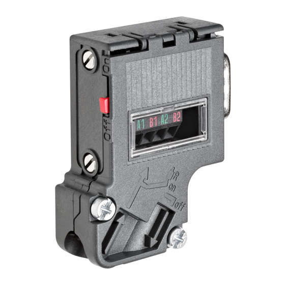
Internet at the following link (http://support.automation.siemens.com/WW/view/en/35222591). Maintenance The PROFIBUS bus connector requires no maintenance. In the event of a fault, contact your Siemens representative responsible for spare parts/repairs: Services (https://support.industry.siemens.com/cs/ww/en/sc/2154) PROFIBUS bus connector... - Page 8 Close the enclosure cover and screw it tight. PG socket (only for 6ES7972-0BB12-0XA0) Note If the switch is set to ON, the PROFIBUS to the other stations is disconnected at this point (e.g. for service purposes). Bus connection for the first and last station on the PROFIBUS Cable must always be connected on the left (see marking A1, B1), switch position must be "ON"...
- Page 9 Cable feed must always be connected on the left (see marking A1, B1). Cable continuation must always be connected on the right (see label A2, B2). Switch position must be "OFF" for all other stations on the PROFIBUS. (terminating resistor switched off). PROFIBUS bus connector...
- Page 10 Device description 3.1 6ES7972-0Bx12-0XA0 Connection PROFIBUS bus connector Equipment Manual, 02/2021, A5E50543113-AA...
- Page 11 Device description 3.1 6ES7972-0Bx12-0XA0 Approvals You can find information on the approvals under Standards, approvals and safety notes (Page 31). Module-specific data You can find information under Module-specific data (Page 38). PROFIBUS bus connector Equipment Manual, 02/2021, A5E50543113-AA...
-
Page 12: 6Es7972-0Ba30-0Xa0
6ES7 972-0BA30-0XA0: Description Cable shield Bus cable, 6XV1 830-0AH10 Bus connection for the stations on the PROFIBUS where no terminating resistor is connected. Description 9-pin D-sub connector for connection at the station (pin 3 and 8 allocated) Housing screws Screws for fastening to the station... - Page 13 Approvals You can find information on the approvals under Standards, approvals and safety notes (Page 31). Module-specific data You can find information under Module-specific data (Page 38). PROFIBUS bus connector Equipment Manual, 02/2021, A5E50543113-AA...
-
Page 14: 6Es7972-0Bx42-0Xa0
Internet at the following link (http://support.automation.siemens.com/WW/view/en/35222591). Maintenance The PROFIBUS bus connector requires no maintenance. In the event of a fault, contact your Siemens representative responsible for spare parts/repairs: Services (https://support.industry.siemens.com/cs/ww/en/sc/2154) PROFIBUS bus connector... - Page 15 Close the enclosure cover and screw it tight. PG socket (only for 6ES7972-0BB42-0XA0) Note If the switch is set to ON, the PROFIBUS to the other stations is disconnected at this point (e.g. for service purposes). PROFIBUS bus connector Equipment Manual, 02/2021, A5E50543113-AA...
- Page 16 Bus connection for the first and last station on the PROFIBUS Cable must always be connected on the left (see marking A1, B1), switch position must be "ON" for the first and last station on the PROFIBUS. (terminating resistor switched on). Bus connection for all other stations on the PROFIBUS Cable feed must always be connected on the left (see marking A1, B1).
- Page 17 Device description 3.3 6ES7972-0Bx42-0XA0 Approvals You can find information on the approvals under Standards, approvals and safety notes (Page 31). PROFIBUS bus connector Equipment Manual, 02/2021, A5E50543113-AA...
-
Page 18: 6Es7972-0Bx52-0Xa0
Internet at the following link (http://support.automation.siemens.com/WW/view/en/35222591). Maintenance The PROFIBUS bus connector requires no maintenance. In the event of a fault, contact your Siemens representative responsible for spare parts/repairs: Services (https://support.industry.siemens.com/cs/ww/en/sc/2154) PROFIBUS bus connector... - Page 19 Note If the switch is set to ON, the PROFIBUS to the other stations is disconnected at this point (e.g. for service purposes). PROFIBUS bus connector...
- Page 20 Bus connection for the first and last station on the PROFIBUS Cable must always be connected on the left (see marking A1, B1), switch position must be "ON" for the first and last station on the PROFIBUS. (terminating resistor switched on). Bus connection for all other stations on the PROFIBUS Cable feed must always be connected on the left (see marking A1, B1).
- Page 21 Device description 3.4 6ES7972-0Bx52-0XA0 Approvals Standards, approvals and safety notes (Page 31) PROFIBUS bus connector Equipment Manual, 02/2021, A5E50543113-AA...
-
Page 22: 6Es7972-0Bx61-0Xa0
Internet at the following link (http://support.automation.siemens.com/WW/view/en/35222591). Maintenance The PROFIBUS bus connector requires no maintenance. In the event of a fault, contact your Siemens representative responsible for spare parts/repairs: Services (https://support.industry.siemens.com/cs/ww/en/sc/2154) PROFIBUS bus connector... - Page 23 Press cable into recess (cable sheath must not rest on the shield plate) Close the enclosure cover and screw it tight. PG socket (only for 6ES7972-0BB61-0XA0) Note The tightening torque of the locking screws (marked in the figure) must not exceed 0.3Nm. PROFIBUS bus connector Equipment Manual, 02/2021, A5E50543113-AA...
- Page 24 Note If the switch is set to ON, the PROFIBUS to the other stations is disconnected at this point (e.g. for service purposes). Bus connection for the first and last station on the PROFIBUS Cable must always be connected on the left (see marking A1, B1), switch position must be "ON"...
- Page 25 Cable feed must always be connected on the left (see marking A1, B1). Cable continuation must always be connected on the right (see label A2, B2). Switch position must be "OFF" for all other stations on the PROFIBUS. (terminating resistor switched off). Approvals...
-
Page 26: 6Es7972-0Bx70-0Xa0
Internet at the following link (http://support.automation.siemens.com/WW/view/en/35222591). Maintenance The PROFIBUS bus connector requires no maintenance. In the event of a fault, contact your Siemens representative responsible for spare parts/repairs: Services (https://support.industry.siemens.com/cs/ww/en/sc/2154) PROFIBUS bus connector... - Page 27 Cable shield must be bare on the metal guide Close strain relief and screw down PG socket (only for 6ES7972-0BB70-0XA0) Note Do not pull the mounted bus cable to open the contact cover! PROFIBUS bus connector Equipment Manual, 02/2021, A5E50543113-AA...
- Page 28 "ON" for the first and last station on the PROFIBUS. (terminating resistor switched on). Note If the switch is set to ON, the PROFIBUS to the other stations is disconnected at this point (e.g. for service purposes). Bus connection for all other stations on the PROFIBUS Cable feed must always be connected on the left (see marking A1, B1).
- Page 29 Device description 3.6 6ES7972-0Bx70-0XA0 Approvals You can find information on the approvals under Standards, approvals and safety notes (Page 31). PROFIBUS bus connector Equipment Manual, 02/2021, A5E50543113-AA...
- Page 30 Device description 3.6 6ES7972-0Bx70-0XA0 Module-specific data You can find information under Module-specific data (Page 38). PROFIBUS bus connector Equipment Manual, 02/2021, A5E50543113-AA...
-
Page 31: Technical Specifications
Always switch off the power before disconnecting plug-in connections in hazardous areas. WARNING Explosion hazard If you replace components, compliance with Class I, Div. 2 or zone 2 may become invalid. PROFIBUS bus connector Equipment Manual, 02/2021, A5E50543113-AA... - Page 32 These five safety rules must be applied in the above order prior to starting work on an electrical system. After completing the work, proceed in the reverse order. It is assumed that every electrician is familiar with these rules. PROFIBUS bus connector Equipment Manual, 02/2021, A5E50543113-AA...
- Page 33 Digital Industries Factory Automation DI FA TI COS TT Postfach 1963 D-92209 Amberg They are also available for download on the Siemens Industry Online Support (http://www.siemens.com/automation/service&support) website, keyword "Declaration of Conformity". cULus approval Underwriters Laboratories Inc., complying with • UL 508 (Industrial Control Equipment) OR UL 61010-1 and UL 61010-2-201 •...
- Page 34 • This equipment is suitable for use in Class I, Division 2, Groups A, B, C, D; Class I, Zone 2, Group IIC; or non-hazardous locations. WARNING: EXPOSURE TO SOME CHEMICALS MAY DEGRADE THE SEALING PROPERTIES OF MATERIALS USED IN THE RELAYS. PROFIBUS bus connector Equipment Manual, 02/2021, A5E50543113-AA...
- Page 35 2. The device must be installed in a suitable housing that ensures at least IP54 degree of protection according to IEC 60079-15 or IEC 60079-7. The ambient conditions must be taken into consideration for use. PROFIBUS bus connector Equipment Manual, 02/2021, A5E50543113-AA...
- Page 36 The devices meet the requirements and criteria of the IEC 61010-2-201 standard. (Safety requirements for electrical equipment for measurement, control, and laboratory use Part 2-201: Particular requirements for control equipment). PROFIBUS standard The devices are based on standard IEC 61158 Type 3. PROFIBUS bus connector Equipment Manual, 02/2021, A5E50543113-AA...
- Page 37 The devices are not intended for use in residential areas. If you use the devices in residential areas, radio or television reception may be affected. Reference The certificates for the markings and approvals can be found on the Internet under Service&Support (http://www.siemens.com/automation/service&support). PROFIBUS bus connector Equipment Manual, 02/2021, A5E50543113-AA...
-
Page 38: Module-Specific Data
Technical specifications 4.3 Module-specific data Module-specific data PROFIBUS bus connector plug with/without PG socket up to 12 Mbaud • 6ES7972-0BA12-0XA0 • 6ES7972-0BB12-0XA0 Article number 6ES7972-0BA12-0XA0 6ES7972-0BB12-0XA0 General information Product description PROFIBUS bus connector, RS PROFIBUS bus connector, RS 485, screw, without pro- 485, screw, with program- gramming port, 90°... - Page 39 Article number 6ES7972-0BA30-0XA0 General information Product description PROFIBUS bus connector, RS 485, Fast Connect, without programming port, 30° Suitability for use For connecting PROFIBUS stations to the PROFIBUS bus cable Interfaces PROFIBUS DP 9.6 kbit/s • Transmission rate, min. 1.5 Mbit/s •...
- Page 40 57.6 mm Depth 39.5 mm Weights Weight (without packaging) 30 g Scope of supply Delivery quantity in pieces PROFIBUS bus connector plug with/without PG socket up to 12 Mbaud • 6ES7972-0BA42-0XA0 • 6ES7972-0BB42-0XA0 Article number 6ES7972-0BA42-0XA0 6ES7972-0BB42-0XA0 General information Product description...
- Page 41 39.5 mm Weights Weight (without packaging) 29 g 34 g Scope of supply Delivery quantity in pieces PROFIBUS FastConnect bus connector with/without PG socket up to 12 Mbaud • 6ES7972-0BA52-0XA0 • 6ES7972-0BB52-0XA0 Article number 6ES7972-0BA52-0XA0 6ES7972-0BB52-0XA0 General information Product description...
- Page 42 9-pin sub D connector 9-pin sub D connector nents/terminal equipment Programming device socket FastConnect cable design Number of electrical connections for PROFIBUS lines Number of electrical connections for network components and terminal devices Mechanics/material Type of terminating resistor Resistor combination inte-...
- Page 43 Technical specifications 4.3 Module-specific data PROFIBUS FastConnect bus connector with/without PG socket up to 12 Mbaud • 6ES7972-0BA61-0XA0 • 6ES7972-0BB61-0XA0 Article number 6ES7972-0BA61-0XA0 6ES7972-0BB61-0XA0 General information Product description PROFIBUS bus connector, RS PROFIBUS bus connector, RS 485, Fast Connect, without 485, Fast Connect, with programming port, 35°...
- Page 44 6ES7972-0BA61-0XA0 6ES7972-0BB61-0XA0 Weights Weight (without packaging) 29 g 34 g Scope of supply Delivery quantity in pieces PROFIBUS FastConnect bus connector with/without PG socket up to 12 Mbaud • 6ES7972-0BA70-0XA0 • 6ES7972-0BB70-0XA0 Article number 6ES7972-0BA70-0XA0 6ES7972-0BB70-0XA0 General information Product description...
- Page 45 Strain relief Dimensions Width 15.8 mm 15.8 mm Height 72 mm 72 mm Depth 36.4 mm 36.4 mm Weights Weight (without packaging) 34 g 45 g Scope of supply Delivery quantity in pieces PROFIBUS bus connector Equipment Manual, 02/2021, A5E50543113-AA...
-
Page 46: Safety-Related Symbols
Be aware that the device is only approved for the industrial field and only for in- door use. Note that an enclosure is required for installing the device. Enclosures are consid- ered: • Standing control cabinet • Serial control cabinet • Terminal boxes • Wall enclosure PROFIBUS bus connector Equipment Manual, 02/2021, A5E50543113-AA... -
Page 47: Safety-Related Symbols For Devices With Ex Protection
Note that a device of Protection Class III may only be supplied with a protective low voltage according to the standard SELV/PELV. IEC 60417-1-5180 "Class III equipment" Be aware that the device is only approved for the industrial field and only for in- door use. PROFIBUS bus connector Equipment Manual, 02/2021, A5E50543113-AA... - Page 48 ≥ IP54. For Zone 22 potentially explosive atmospheres, be aware that the device may only be used when it is installed in an enclosure with a degree of protection ≥ IP6x. PROFIBUS bus connector Equipment Manual, 02/2021, A5E50543113-AA...
-
Page 49: Index
37 in mixed areas, 37 in residential areas, 37 Approvals, 31 IEC 61010, 36 IEC 61010, 36 Radio interference, 37 Safety rules, 32 Standards, 31 Technical specifications Standards and approvals, 31 PROFIBUS bus connector Equipment Manual, 02/2021, A5E50543113-AA... - Page 50 Index PROFIBUS bus connector Equipment Manual, 02/2021, A5E50543113-AA...