
Related Manuals for Bosch Rexroth IndraMotion MLC


Summary of Contents for Bosch Rexroth IndraMotion MLC
- Page 1 IndraMotion IndraControl VPB 40.4 Operating Instructions Edition 02 R911383090...
- Page 2 Edition 02, 2018-10 Refer to tab. 1-1 "Change Record" on page 1 Copyright © Bosch Rexroth AG 2018 All rights reserved, also regarding any disposal, exploitation, reproduction, editing, distribution, as well as in the event of applications for industrial property rights.
-
Page 3: Table Of Contents
IndraControl VPB 40.4 Bosch Rexroth AG Table of Contents Table of Contents Page About this documentation..............1 Overview on target groups and product phases........Purpose....................Scope....................Related documents................2 Customer feedback................Product identification and scope of delivery........Product identification................2 Scope of delivery................... - Page 4 Bosch Rexroth AG IndraControl VPB 40.4 Table of Contents Page CE marking ..................UL/CSA certified................. Interfaces.................... Overview..................... PC voltage supply X10................. 14 Reset button..................15 USB interfaces XUSB1 to XUSB6............16 Ethernet interfaces XETH1 and XETH2..........17 Display port XDP.................
- Page 5 IndraControl VPB 40.4 Bosch Rexroth AG Table of Contents Page Device description................41 12.1 Components..................41 12.1.1 Hardware..................... 41 12.1.2 Software....................41 12.2 Connections, operating elements and LEDs........12.3 Operating and error displays............... 44 12.4 Backing up remanent data..............45 12.5...
- Page 6 Bosch Rexroth AG IndraControl VPB 40.4 Table of Contents Page 16.1 Return....................80 16.2 Packaging.................... 16.3 Batteries and accumulators..............80 Service and support................80 Index....................83 DOK-MLC***-INDRACTRLV4-IT02-EN-P...
-
Page 7: About This Documentation
IndraControl VPB 40.4 Bosch Rexroth AG About this documentation 1 About this documentation Editions of this documentation Edition Release Note Date 2017-11 First edition 2018-10 Two slot device supplemented Tab. 1-1: Change Record 1.1 Overview on target groups and product phases In the following illustration, the framed activities, product phases and target groups refer to the present documentation. -
Page 8: Scope
Customer requests, comments or suggestions for improvement are of great importance to us. Please email your feedback on the documentations to Feedback.Documentation@boschrexroth.de. Directly insert comments in the electronic PDF document and send the PDF file to Bosch Rexroth. 2 Product identification and scope of delivery 2.1 Product identification The type plate is located on the rear side or at the side of the device. -
Page 9: Scope Of Delivery
MNR: R911171065 -GA1 FD: 11W40 : AC 230V/115V, DC 24V 10,3A : 2,7A/5A, SN: 004012652 I-C-B-H-T-V IND. CONT-EQ 18WM Bosch Rexroth Electric Drives and Controls GmbH Made in Germany D-64711 Erbach IND.CONT.EQ 17YB Front Mounted Type1 I-C-B-H-T-V FD: 12W27 SN:008595411... -
Page 10: Explaining Signal Words And Safety Alert Symbol
Bosch Rexroth AG IndraControl VPB 40.4 Using safety instructions 3.2 Explaining signal words and safety alert symbol The safety instructions in this documentation contain specific signal words (danger, warning, caution, notice) and, if necessary, a safety alert symbol (according to ANSI Z535.6-2006). -
Page 11: Explaining The Signal Alert Symbol On The Device
IndraControl VPB 40.4 Bosch Rexroth AG Intended use 3.4 Explaining the signal alert symbol on the device If this symbol is on your device, you have to observe the documentation on the device. The respective documentation informs on the type of hazard as well as the steps required to avoid this hazard. -
Page 12: Spare Parts, Accessories And Wear Parts
Bosch Rexroth AG IndraControl VPB 40.4 Spare parts, accessories and wear parts 5 Spare parts, accessories and wear parts 5.1 Y-repeater Connecting unit to connect two operator displays with the same resolution and the same version to one control cabinet PC. -
Page 13: Usb Connecting Cable
IndraControl VPB 40.4 Bosch Rexroth AG Spare parts, accessories and wear parts Two cables are always required to establish a connection between the VPB and the VDP. 5.5 USB connecting cable Ordering code Part number Description RKB0019/000,5 (*******-*******-*******) R911171165 connecting cable, length 0.5 m... -
Page 14: Solid State Drive
Bosch Rexroth AG IndraControl VPB 40.4 Ambient conditions 5.7.3 Solid State Drive The SSD (Solid State Drive) shock resistance and temperature resistance is higher than of an ordinary hard disk. The hard disk is only subject to electrical and not to mechanical wear. - Page 15 IndraControl VPB 40.4 Bosch Rexroth AG Ambient conditions In operation Transport Storage Mechanical Max. Vibration: Max. Shock: Max. Shock: strength Frequency range: 15 g 11 ms 15 g 11 ms 10 Hz to 150 Hz Acc. to EN 60068-2-27 Acc. to EN 60068-2-27 Excursion: 0.75 mm at 10 Hz to 57 Hz...
-
Page 16: Technical Data
Bosch Rexroth AG IndraControl VPB 40.4 Technical data This is a product that corresponds to the limit values of the emitted interference of class A (industrial environments), but not of class B (residential area and small enterprises). When using the product in residential areas or small enterprises, the operator has to take actions to prevent radio interferences (also refer to DIN EN 55022). -
Page 17: Standards
IndraControl VPB 40.4 Bosch Rexroth AG Standards PC box Type P Type R Max. Power 150 W consumption Weight Approx. 2.6 kg Approx. 3.3 kg Tab. 7-1: Technical data of the PC box The specified maximum power consumption includes the power consumption of the extension cards, refer to chapter 9.9.2 "Power drain of the extension cards"... -
Page 18: Ce Marking
Bosch Rexroth AG IndraControl VPB 40.4 Standards Standard Title IEC 60721-3-2 Classification of environmental conditions Part 3: Classification of groups of environmental parameters and their severities Section 2: Transportation IEC 60721-3-3 Classification of environmental conditions Part 3: Classification of groups of environmental parameters and their... -
Page 19: Interfaces
IndraControl VPB 40.4 Bosch Rexroth AG Interfaces UL508 (Industrial Control Equipment) ● C22.2 no. 142-M1987 (CSA) ● UL file no. E210730 However, there can be combinations or extension stages with a limited or missing certification. Thus, verify the registration according to the UL marking on the device. -
Page 20: Pc Voltage Supply X10
Bosch Rexroth AG IndraControl VPB 40.4 Interfaces Name at the Connection type Connection type Mating connector or cable housing (at the device) (from outside) XETH1, XETH2 Ethernet interfaces RJ45 socket, 8-pin RJ45 plug 10/100/1000 Base-T (Twisted pair, 8-wire) XUSB1 to XUSB6 USB interfaces... -
Page 21: Reset Button
IndraControl VPB 40.4 Bosch Rexroth AG Interfaces Labeling Function Supply voltage 24 V – 0 V supply voltage Supply voltage available in front of the UPS (see chapter 10.3.2 "Connecting a UPS" on page NOTICE Destruction of the control cabinet PC (fire... -
Page 22: Usb Interfaces Xusb1 To Xusb6
Bosch Rexroth AG IndraControl VPB 40.4 Interfaces Please use the “Reset” button only in exceptional cases, e.g. if the operating system does not respond anymore when keypad or mouse are used. Data that is not saved on the hard disk or on other storage media, is lost after a reset. -
Page 23: Ethernet Interfaces Xeth1 And Xeth2
IndraControl VPB 40.4 Bosch Rexroth AG Interfaces If there is an mPCIe module internally, a USB 2.0 device connected to XUSB5 does not operate anymore. A possibly connected USB 3.0 device is still functioning. 9.5 Ethernet interfaces XETH1 and XETH2 The control cabinet PC can be connected to an Ethernet network via the Ethernet interfaces XETH1 and EXTH2. -
Page 24: Cdi Interfaces Xvid And Xser
Bosch Rexroth AG IndraControl VPB 40.4 Interfaces The BIOS is configured and thus ensures that all connected output devices can be controlled while booting. If IndraControl VPB 40.4 is supposed to simultaneously output the screen on a connected monitor at the display port and at the VDP... -
Page 25: Internal Interfaces
IndraControl VPB 40.4 Bosch Rexroth AG Interfaces CDI interface, data (XSER) Violet CDI interface, image (XVID) Black 9.8 Internal interfaces There are three more interfaces internally: 1 × USB 3.0 ● 1 × mSATA ● 1 × mPCIe ● The USB 3.0 interface is intended for USB devices that have to be connected ●... -
Page 26: Mounting, Demounting And Electric Installation
Bosch Rexroth AG IndraControl VPB 40.4 Mounting, demounting and electric installation 10 Mounting, demounting and electric installation 10.1 Installation notes 10.1.1 Cables routing Lay all connecting cables in loops and use strain reliefs for all cables ● Keep the maximum distance possible from interference sources ●... -
Page 27: Internal Connections For Usb, Msata Modules And Mpcie Mod- Ules
IndraControl VPB 40.4 Bosch Rexroth AG Mounting, demounting and electric installation 10.1.3 Internal connections for USB, mSATA modules and mPCIe mod- ules ① ③ USB 3.0 mPCIe ② mSATA Fig. 10-2: Position of the internal interfaces Possible restrictions for the 2-slot variant: When using a PCI card or a PCIe card with a card length >... - Page 28 Bosch Rexroth AG IndraControl VPB 40.4 Mounting, demounting and electric installation NOTICE Damages to the device due to electrostatic discharges! Comply with all ESD protective measures while working with modules and components! Avoid electrostatic discharges! NOTICE Risk of damage to the IndraControl VPB 40.4 by...
-
Page 29: Installing Extension Cards
IndraControl VPB 40.4 Bosch Rexroth AG Mounting, demounting and electric installation ① Fastening screw of the housing cover of 2-slot variants ② Fastening screws of the housing cover of 4-slot variants Fig. 10-3: Position of the housing cover and the fastening screw(s) 7. - Page 30 Bosch Rexroth AG IndraControl VPB 40.4 Mounting, demounting and electric installation 2. If operated with a UPS, wait until the control cabinet PC switches off automatically. The UPS LED on the connector panel of the control cabinet PC is red until the UPS switches off the power supply unit.
- Page 31 IndraControl VPB 40.4 Bosch Rexroth AG Mounting, demounting and electric installation ① ③ Fastening screws of the housing cov- 4 PCI/PCIe slots (depends on the PC er (internal hexagon T10) box type) ② Fastening screws of the slot covers (internal hexagon T10) Fig.
-
Page 32: Bios Settings
Bosch Rexroth AG IndraControl VPB 40.4 Mounting, demounting and electric installation IRQ (Interrupt) conflict with other PC hardware components of the control ● cabinet PC The software of the card was not installed ● 10.1.6 BIOS settings No further settings have to be made in the BIOS setup. The corresponding settings have already been set for the normal operation. - Page 33 IndraControl VPB 40.4 Bosch Rexroth AG Mounting, demounting and electric installation ① Keyhole for vertical mounting ② Slots to hang in the device Fig. 10-6: Housing dimensions for devices with two slots, vertical mounting 27/87 DOK-MLC***-INDRACTRLV4-IT02-EN-P...
- Page 34 Bosch Rexroth AG IndraControl VPB 40.4 Mounting, demounting and electric installation ① Keyholes for horizontal mounting ② Slots to hang in the device Fig. 10-7: Housing dimensions for devices with two slots, horizontal mounting 28/87 DOK-MLC***-INDRACTRLV4-IT02-EN-P...
- Page 35 IndraControl VPB 40.4 Bosch Rexroth AG Mounting, demounting and electric installation ① Keyhole for vertical mounting ② Slots to hang in the device Fig. 10-8: Housing dimensions, devices with four slots, vertical mounting 29/87 DOK-MLC***-INDRACTRLV4-IT02-EN-P...
- Page 36 Bosch Rexroth AG IndraControl VPB 40.4 Mounting, demounting and electric installation 17,5 21,5 17,5 ① Keyholes for horizontal mounting ② Slots to hang in the device Fig. 10-9: Housing dimensions, devices with four slots, horizontal mounting 30/87 DOK-MLC***-INDRACTRLV4-IT02-EN-P...
- Page 37 IndraControl VPB 40.4 Bosch Rexroth AG Mounting, demounting and electric installation Fig. 10-10: Housing dimensions, devices with two slots, side view from the right 31/87 DOK-MLC***-INDRACTRLV4-IT02-EN-P...
- Page 38 Bosch Rexroth AG IndraControl VPB 40.4 Mounting, demounting and electric installation Fig. 10-11: Housing dimensions, devices with four slots, side view from the right 32/87 DOK-MLC***-INDRACTRLV4-IT02-EN-P...
-
Page 39: Electric Connection
IndraControl VPB 40.4 Bosch Rexroth AG Mounting, demounting and electric installation 10.3 Electric connection 10.3.1 Connecting 24 V supply to the control cabinet PC 1. Connect the functional earth. 2. Connect the "X10" interface for the 24 V voltage supply to the industrial power supply unit or to the UPS (if available). - Page 40 Bosch Rexroth AG IndraControl VPB 40.4 Mounting, demounting and electric installation Overvoltage category I Control cabinet PC Terminal block UK6-FSI/6 VSB 40.3 with automatic cut-out TCP 10 A VSP xx.3 (PHOENIX CONTACT) is recommended VPB 40.3 16 A VPB 40.4 24 V (VAU 01.1)
-
Page 41: Recommendation For The Mounting Of Cdi Cables With Long Lengths In An Interference-Prone Environment
IndraControl VPB 40.4 Bosch Rexroth AG Mounting, demounting and electric installation USB cable USB connector USB connector Type A Type B 230V~ X1S1 Ext. power supply 230V X1S (X10) X1S2 Panel or control cabinet PC Fig. 10-13: Total connection scheme with power supply unit, UPS and panel PC or control cabinet PC for IndraMotion MLC VPB 40.4... - Page 42 Bosch Rexroth AG IndraControl VPB 40.4 Mounting, demounting and electric installation ensure that the cable is installed correctly and that the shield is connected correctly. Cables routing Observe the following when routing cables: Keep the maximum possible distance to interference-prone cables and lines ●...
- Page 43 IndraControl VPB 40.4 Bosch Rexroth AG Mounting, demounting and electric installation Fig. 10-14: RJ45 plug shielding areas Additional shielding connection in case of strong electrical interferences and long cables In case of strong electrical interferences and long cable lengths, it can be required to additionally connect the shielding to the earthing potential.
- Page 44 Bosch Rexroth AG IndraControl VPB 40.4 Mounting, demounting and electric installation Fig. 10-16: CDI cable with partially removed jacket 2. Remove the foil shield. CDI cables are equipped with an additional foil shield. The foil shield must not be used for the connection. The foil shield is usually plastic-coated on one side for an improved stability.
-
Page 45: Commissioning
IndraControl VPB 40.4 Bosch Rexroth AG Commissioning Fig. 10-19: Example: Attached shielding clamp More shielding clamps: ① Company Ikotec ② Company Phoenix Contact Fig. 10-20: Shielding clamps 11 Commissioning 11.1 Commissioning steps The product can be used directly without any configuration. -
Page 46: Software Tools
Bosch Rexroth AG IndraControl VPB 40.4 Commissioning The project planning and programming software "IndraWorks Engineering" has to be installed in the system variant IndraWorks ML* on the project planning PC. 6. Create an IndraWorks project. Refer to chapter 12.10.1 "Creating the control" on page 7. -
Page 47: Device Description
IndraMotion MLC. The project planning and programming of the integrated control are carried out as for the common controller-based control solutions based on the IndraControl CML or IndraControl XM using the Bosch Rexroth Engineering Suite IndraWorks. The architecture has the following characteristics: High performance due to comprehensive functions and interfaces ●... - Page 48 Bosch Rexroth AG IndraControl VPB 40.4 Device description IndraControl Systray (refer to chapter 12.9 "IndraControl SysTray" on page ● IndraControl initial firmware (chapter 12.7 "Initial firmware" on page ● IndraControl First Touch (chapter 12.8 "IndraControl First Touch" on page ●...
-
Page 49: Connections, Operating Elements And Leds
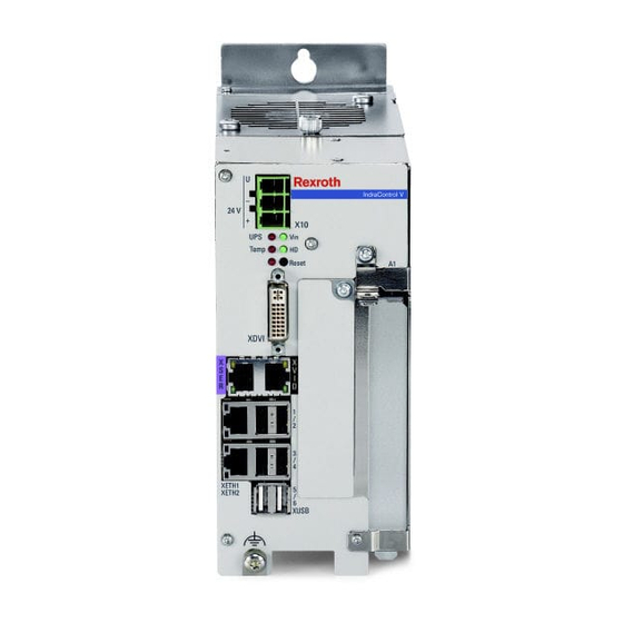
IndraControl VPB 40.4 Bosch Rexroth AG Device description 12.2 Connections, operating elements and LEDs ① ② Key holes for mounting (also provided at ③ the bottom side) Plug for voltage supply 43/87 DOK-MLC***-INDRACTRLV4-IT02-EN-P... -
Page 50: Operating And Error Displays
Bosch Rexroth AG IndraControl VPB 40.4 Device description ④ ⑪ Status LEDs and “Reset” button XF02 connection with LEDs L/S ⑤ ⑫ Display port connection XF41 connection with LEDs L/S ⑥ ⑬ CDI interface (data interface and image XF40 connection with LEDs L/S ⑭... -
Page 51: Backing Up Remanent Data
IndraControl VPB 40.4 Bosch Rexroth AG Device description Display Description Action LED flashing Hard disk access – green LED is flashing Warning: SMART analysis is identifying Exchange hard disk green with a errors. flashing Observe that this warning message is not... - Page 52 Bosch Rexroth AG IndraControl VPB 40.4 Device description a transparent and safe communication between the control functionality and the running Windows applications. To exchange data between the Windows applications and the control system, a "shared memory" and a virtual network adapter are provided by the system.
- Page 53 IndraControl VPB 40.4 Bosch Rexroth AG Device description Fig. 12-2: Hypervisor – Architecture IndraControl VPB 40.4 The distribution of the hardware resources to the respective operating system is defined as follows: Resource Function Assignment CPU Core 1 to 3 Processor...
-
Page 54: Network File System (Nfs)
Bosch Rexroth AG IndraControl VPB 40.4 Device description Ethernet interface Communication interface of the control VxWorks (control) XETH2 IndraMotion MLC VPB (default 192.168.1.1). The address can only be changed via IndraControl First Touch XUSB 1-6 USB host Windows XDVI/XVID Graphics... -
Page 55: Starting And Opening The Initial Firmware
IndraControl VPB 40.4 Bosch Rexroth AG Device description 12.7.1 Starting and opening the initial firmware The IndraMotion MLC based on the hardware IndraControl VPB does not include any MLC system firmware upon delivery. If the MLC system firmware has not yet been installed on the device, the initial firmware is enabled upon each industrial PC startup. -
Page 56: Hardware Data
Bosch Rexroth AG IndraControl VPB 40.4 Device description The default user ID is: User name: boschrexroth ● Password: boschrexroth ● Fig. 12-3: "Welcome" dialog 12.8.1 Hardware data The "Hardware" site lists all device-specific data of the IndraMotion MLC based on the hardware IndraControl VPB in a table. -
Page 57: Firmware Management
IndraControl VPB 40.4 Bosch Rexroth AG Device description Fig. 12-4: "Network configuration" dialog The network settings are only applied after a control restart. 12.8.3 Firmware management The menu items are only available in this dialog if the initial firmware is active. - Page 58 Bosch Rexroth AG IndraControl VPB 40.4 Device description Fig. 12-5: "Firmware management" dialog Current control mode: ● – Initial mode: Initial firmware is loaded or active (initial firmware is shown in the message window) – System mode: The control was started with the previously installed MLC system firmware Installed system firmware version ("none"...
- Page 59 IndraControl VPB 40.4 Bosch Rexroth AG Device description The file name of a system archive can consist of 4-16 alphanumerical characters and has to have the file extension ".fw". The backup can only be started if the selected file name corresponds to the archive rules.
- Page 60 Bosch Rexroth AG IndraControl VPB 40.4 Device description Fig. 12-7: "Archive SYSTEM/OEM/USER:" dialog – Archive file was created successfully Restore SYSTEM/OEM/USER If the action "Restore SYSTEM/OEM/USER" is selected, a modal dialog opens to select a previously generated archive file. The source file can either be selected from the local file system or the USER partition of the control.
- Page 61 IndraControl VPB 40.4 Bosch Rexroth AG Device description Fig. 12-8: "Restore SYSTEM/OEM/USER" dialog – Uploading an archive file Fig. 12-9: "Restore SYSTEM/OEM/USER" dialog – Archive is restored 55/87 DOK-MLC***-INDRACTRLV4-IT02-EN-P...
- Page 62 Bosch Rexroth AG IndraControl VPB 40.4 Device description Fig. 12-10: "Restore SYSTEM/OEM/USER" dialog – Archive was restored successfully If the archive file is selected from the USER partition, it is directly installed after pressing "Install". The table lists all firmware files found in the root directory of the USER partition.
-
Page 63: File Manager
IndraControl VPB 40.4 Bosch Rexroth AG Device description 12.8.4 File manager The "File manager" dialog is used to: Browse through the directory structure (click on a directory name) ● Transfer files from the control to the client (click on a file name) ●... -
Page 64: Context Menu
Bosch Rexroth AG IndraControl VPB 40.4 Device description 12.9.1 Context menu Right-click on the icon of the application to display the context menu. Items in the menu are displayed depending on the status “active” (black) or “inactive” (grey). Menu Subfunction... -
Page 65: Dialogs
IndraControl VPB 40.4 Bosch Rexroth AG Device description State, tooltip Icon Description System firmware is loaded and ready. At least one PLC application was started Stop System firmware is loaded and not ready. All loaded PLC applications are stopped Boot stop... - Page 66 Bosch Rexroth AG IndraControl VPB 40.4 Device description Fig. 12-13: Diagnostics and settings Status display: Coloring and naming of the LEDs depend on the system and are specified in the respective system documentation. For a description of the individual LEDs, refer to the chapter "Operating and display elements"...
- Page 67 IndraControl VPB 40.4 Bosch Rexroth AG Device description Example: Boot stop was enabled. Fig. 12-14: Diagnostics and settings – Boot stop enabled Next function: Call the next function. Activate function: Enable the selected function. The function normally runs within some seconds. Thus, wait for feedback of the system with regard to the respectively selected function.
-
Page 68: Indraworks Engineering
Device description Fig. 12-15: "About" dialog 12.10 IndraWorks Engineering To commission and project the Bosch Rexroth IndraMotion MLC control, the software "IndraWorks Engineering" is provided. Use IndraWorks Engineering to resolve all tasks of the PLC-based automation and drive commissioning in a uniform and intuitively operable software environment. -
Page 69: Creating The Control
IndraControl VPB 40.4 Bosch Rexroth AG Device description 12.10.1 Creating the control To continue with the commissioning of the control, proceed as follows: 1. Start IndraWorks Engineering Start IndraWorks Engineering on your project planning PC. 2. Create a project Start IndraWorks Engineering and select "Empty project" as template. - Page 70 Bosch Rexroth AG IndraControl VPB 40.4 Device description 4. General settings Fig. 12-17: MLC commissioning wizard: Step 1 Device name, comments on the project as well as information on the author are stored in the dialog "Step 1: General settings". To continue with the configuration, press Next>>.
- Page 71 IndraControl VPB 40.4 Bosch Rexroth AG Device description Fig. 12-18: MLC commissioning wizard: Step 2 Enter the IP address of the MLC control to be projected into the section "Ethernet communication". To check the connection to the MLC control, click on "Execute" in the "Connection test"...
- Page 72 Bosch Rexroth AG IndraControl VPB 40.4 Device description Fig. 12-19: MLC commissioning wizard: Step 3 7. Select the function package Select the checkboxes for the function packages purchased with your control in "Step 4: Function packages". 66/87 DOK-MLC***-INDRACTRLV4-IT02-EN-P...
- Page 73 IndraControl VPB 40.4 Bosch Rexroth AG Device description Fig. 12-20: MLC commissioning wizard: Step 4 Confirm the dialog with Next>>. 8. Select the I/O interfaces Select the configuration of the extension cards for the I/O connection in "Step 5: Interfaces".
- Page 74 Bosch Rexroth AG IndraControl VPB 40.4 Device description Fig. 12-21: MLC commissioning wizard: Step 5 Complete the dialog with Finish. Now, the final steps to create the device IndraMotion MLC VPx in the IndraWorks project are automatically executed. 9. Project planning After the MLC device has been created in the project tree, the device is available for parameterization and programming.
-
Page 75: Firmware Download
IndraControl VPB 40.4 Bosch Rexroth AG Device description Fig. 12-22: Initial project in IndraWorks 12.10.2 Firmware download 1. Selecting the control Upon delivery of the device or when using a new MLC release, load the system firmware to the device. Highlight the corresponding device in the project tree and select the item "Firmware management"... - Page 76 Bosch Rexroth AG IndraControl VPB 40.4 Device description Fig. 12-23: Starting the IndraWorks firmware management 2. Selecting system firmware Select the system firmware for your device. To select the firmware from the IndraWorks installation, go to "Firmware of installation". Alternatively, a firmware from any memory location on your PC can selected via "Firmware...
- Page 77 IndraControl VPB 40.4 Bosch Rexroth AG Device description Fig. 12-24: Firmware selection 3. Downloading firmware Select the system firmware file and press Download. Multiple steps have to be performed. The progress is shown in the dialog window of the firmware management.
- Page 78 Bosch Rexroth AG IndraControl VPB 40.4 Device description Fig. 12-25: Active firmware download 72/87 DOK-MLC***-INDRACTRLV4-IT02-EN-P...
-
Page 79: Remote Connection
IndraControl VPB 40.4 Bosch Rexroth AG Device description NOTICE Damage to the device due to canceled firmware download Do not interrupt the firmware download and the installation. After the download, close the dialog with Close. The system firmware is started. -
Page 80: Error Causes And Troubleshooting
"IndraControl SysTray" on page 1. To set up the remote desktop on the device IndraMotion MLC VPB 40.4, it is required to connect a screen via XDP or a Bosch Rexroth VDP panel via XSER/XVID as well as mouse and keyboard. -
Page 81: Hard Disk(S)
IndraControl VPB 40.4 Bosch Rexroth AG Maintenance NOTICE Dissolving labeling device solvents! Do not use any solvents (e. g. diluents) for cleaning! ● NOTICE Destruction of screw terminals, insufficient contact and loss of UL certification if no copper wire is used or due to wrong tightening torque. - Page 82 Bosch Rexroth AG IndraControl VPB 40.4 Maintenance To avoid data loss and new installations of the operating system and application programs, backup hard disk data regularly. The new hard disk(s), including the installation frame, is/are provided upon delivery. The new hard disk(s) is/are always installed with the installation frame.
-
Page 83: Fan
IndraControl VPB 40.4 Bosch Rexroth AG Maintenance If an SSD (Solid State Drive) is used, avoid defragmentation. Thus, the wear of the SSD reduces. 14.2 Fan The fan is located on the top in the PC box. ① ③ Knurled screw of the fan tray Fan plug connection ②... -
Page 84: Cmos Battery
Bosch Rexroth AG IndraControl VPB 40.4 Ordering information 7. Tighten the knurled screw. The connecting cable of the fan is connected to a PCB via a plug connection. The cable may not be attached to anything and must not be crimped. - Page 85 IndraControl VPB 40.4 Bosch Rexroth AG Ordering information The control cabinet PC IndraControl VPB 40.4 is available in different variants according to the following type code. Type short description 1 2 3 4 5 6 7 8 9 0 1 2 3 4 5 6 7 8 9 0 1 2 3 4 5 6 7 8 9 Example: V P B 4 0 .
-
Page 86: Disposal
Bosch Rexroth AG IndraControl VPB 40.4 Service and support 16 Disposal 16.1 Return For disposal, our products can be returned free of charge. However, the products must be free of remains like oil and grease or other impurities. Furthermore, the products returned for disposal must not contain any undue foreign substances or components. - Page 87 IndraControl VPB 40.4 Bosch Rexroth AG Service and support Service Germany Our technology-oriented Competence Center in Lohr, Germany, is responsible for all your service-related queries for electric drive and controls. Contact the Service Hotline and Service Helpdesk under: Phone: +49 9352 40 5060...
- Page 88 Bosch Rexroth AG IndraControl VPB 40.4 82/87 DOK-MLC***-INDRACTRLV4-IT02-EN-P...
- Page 89 IndraControl VPB 40.4 Bosch Rexroth AG Index Index Accessories........6 Electric connection....... 33 Accumulators........ 80 Emitted interference..... 10 Ambient conditions......8 Error causes........74 ANSI Z535.6-2006......4 Error displays........ 44 Ethernet connection..... 17 Exchanging hard disk....75 Extension cards......19 Batteries........
- Page 90 Bosch Rexroth AG IndraControl VPB 40.4 Index IndraControl First Touch, hard- ware data......... 50 24 V power supply unit....6 IndraControl First Touch, Network File System (NFS)... 48 network settings...... 50 Network settings......50 IndraWorks Engineering, firmware download....69 Initial firmware......48 Operating and error displays..
- Page 91 IndraControl VPB 40.4 Bosch Rexroth AG Index Target groups........1 Technical data....... 10 Tightening torques......75 Troubleshooting......74 Type code........78 Type plate........2 UL/CSA certified......12 Uninterruptible power supply..6 Uninterruptible Power Supply..33 Upon delivery........ 48 UPS........... 6, 33 UPS with USB interface....
- Page 92 Bosch Rexroth AG IndraControl VPB 40.4 86/87 DOK-MLC***-INDRACTRLV4-IT02-EN-P...
- Page 93 IndraControl VPB 40.4 Bosch Rexroth AG Notes...
- Page 94 Bosch Rexroth AG Electric Drives and Controls P.O. Box 13 57 97803 Lohr, Germany Bgm.-Dr.-Nebel-Str. 2 97816 Lohr, Germany Phone +49 9352 18 0 Fax +49 9352 18 8400 www.boschrexroth.com/electrics *R911383090* R911383090 DOK-MLC***-INDRACTRLV4-IT02-EN-P...