Table of Contents
Advertisement
Quick Links
TABLE OF CONTENTS
1 Safety Precautions----------------------------------------------- 2
2 Specifications ----------------------------------------------------- 3
3 Technical Descriptions ----------------------------------------- 4
4 Location of Controls and Components ------------------12
5 Installation Instructions ---------------------------------------14
6 Instruction for Stacking ---------------------------------------14
7 Important Safety Instructions -------------------------------15
8 Types of Container to Use ------------------------------------20
9 Operating Instructions-----------------------------------------22
10 Service Mode -----------------------------------------------------52
11 Troubleshooting Guide ----------------------------------------57
12 Disassembly and Assembly Instructions ---------------62
13 Measurements and Adjustments---------------------------74
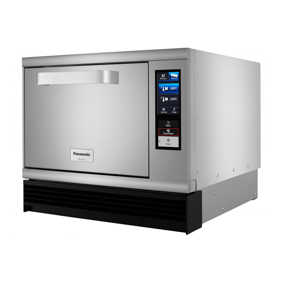
Commercial Microwave Convection Oven
Model No.
Product Colour : Silver
Destination :
PAGE
14 Dimensions ------------------------------------------------------- 75
15 Block Diagram --------------------------------------------------- 76
16 Wiring Connection Diagram--------------------------------- 77
17 Exploded View and Replacement Parts List ----------- 78
Order No.MOD1712487CE
NE-SCV2BPQ
United Kingdom
© Panasonic Corporation 2017 Unauthorized copy-
ing and distribution is a violation of law.
PAGE
Advertisement
Table of Contents

Related Manuals for Panasonic NE-SCV2BPQ


Summary of Contents for Panasonic NE-SCV2BPQ
-
Page 1: Table Of Contents
8 Types of Container to Use ------------------------------------20 9 Operating Instructions-----------------------------------------22 10 Service Mode -----------------------------------------------------52 11 Troubleshooting Guide ----------------------------------------57 12 Disassembly and Assembly Instructions ---------------62 13 Measurements and Adjustments---------------------------74 © Panasonic Corporation 2017 Unauthorized copy- ing and distribution is a violation of law. -
Page 2: Safety Precautions
NE-SCV2BPQ 1 Safety Precautions... -
Page 3: Specifications
NE-SCV2BPQ 2 Specifications Outside Dimensions (W x D x H) 474 mm x 565 mm x 412 mm Cavity Effective Dimensions (W x D x H) 270 mm x 330 mm x 110 mm Cavity Capacity 10 L (approx.) Net Weight 38.3 kg (approx.) -
Page 4: Technical Descriptions
NE-SCV2BPQ 3 Technical Descriptions 3.1. Operation description 3.1.1. Manual cooking operation 3.1.1.1. Preheating... - Page 5 NE-SCV2BPQ 3.1.1.2. Convection Cooking...
- Page 6 NE-SCV2BPQ 3.1.1.3. Grill Cooking...
- Page 7 NE-SCV2BPQ 3.1.1.4. Convection-and-Grill Cooking...
- Page 8 NE-SCV2BPQ 3.1.1.5. Microwave Cooking...
- Page 9 NE-SCV2BPQ 3.1.1.6. Convection-and-Microwave Cooking...
- Page 10 NE-SCV2BPQ 3.1.1.7. Grill-and-Microwave Cooking...
- Page 11 NE-SCV2BPQ 3.1.1.8. Cooling...
-
Page 12: Location Of Controls And Components
NE-SCV2BPQ 4 Location of Controls and Components... - Page 13 NE-SCV2BPQ...
-
Page 14: Installation Instructions
NE-SCV2BPQ 5 Installation Instructions Keep the following proper distances between the outer surfaces of the oven and walls. • Otherwise, overheating can cause damage to the walls, etc., such as burn, deformation or ignition. To ensure the safe use of the oven, keep distances greater than the ones indicated in the table below between its outer surfaces and the walls. -
Page 15: Important Safety Instructions
NE-SCV2BPQ 7 Important Safety Instructions... - Page 16 NE-SCV2BPQ...
- Page 17 NE-SCV2BPQ...
- Page 18 NE-SCV2BPQ...
- Page 19 NE-SCV2BPQ...
-
Page 20: Types Of Container To Use
NE-SCV2BPQ 8 Types of Container to Use... - Page 21 NE-SCV2BPQ...
-
Page 22: Operating Instructions
NE-SCV2BPQ 9 Operating Instructions 9.1. Accessories... - Page 23 NE-SCV2BPQ...
- Page 24 NE-SCV2BPQ...
- Page 25 NE-SCV2BPQ 9.2. How to Operate the Touch Screen...
- Page 26 NE-SCV2BPQ...
- Page 27 NE-SCV2BPQ...
- Page 28 NE-SCV2BPQ...
- Page 29 NE-SCV2BPQ...
- Page 30 NE-SCV2BPQ...
- Page 31 NE-SCV2BPQ...
- Page 32 NE-SCV2BPQ 9.3. Preheating...
- Page 33 NE-SCV2BPQ 9.4. Manual Cooking...
- Page 34 NE-SCV2BPQ...
- Page 35 NE-SCV2BPQ...
- Page 36 NE-SCV2BPQ...
- Page 37 NE-SCV2BPQ...
- Page 38 NE-SCV2BPQ...
- Page 39 NE-SCV2BPQ...
- Page 40 NE-SCV2BPQ 9.5. Memory Cooking...
- Page 41 NE-SCV2BPQ...
- Page 42 NE-SCV2BPQ...
- Page 43 NE-SCV2BPQ...
- Page 44 NE-SCV2BPQ...
- Page 45 NE-SCV2BPQ...
- Page 46 NE-SCV2BPQ 9.6. Care of your Oven...
- Page 47 NE-SCV2BPQ...
- Page 48 NE-SCV2BPQ...
- Page 49 NE-SCV2BPQ 9.7. Regular Maintenance...
- Page 50 NE-SCV2BPQ 9.8. Troubleshooting...
- Page 51 NE-SCV2BPQ 9.9. Self Diagnostics Failure Code...
-
Page 52: Service Mode
NE-SCV2BPQ 10 Service Mode To prevent accidents during repair and ensure your safety after the repair, be sure to read or refer to “Safety Precautions” describing precautions that you must observe when repairing. 10.1. Failure code function In the event of a failure, a failure code is displayed to stop the operation. - Page 53 NE-SCV2BPQ DISPLAY Left circuit Right circuit CONDITIONS RESET CAUSES / REMEDIES • Detection of locked fan of the • Press Pause/Reset button to return • DC fan motor cooling fan motor. to the initial display screen. (Cooling fan for Circulation Fan...
- Page 54 NE-SCV2BPQ 10.1.2. Fan / inverter / Magnetron / thermistor-related failure code Fan / inverter location Where to connect...
- Page 55 NE-SCV2BPQ 10.2. Procedure for showing the failure code 10.2.1. How to call up or erase the memory Follow the steps below to call up the failure code. • If you call up a failure code that is not stored in memory, the message “No Failure code” appears.
- Page 56 NE-SCV2BPQ Operation LCD Display Remark Press the "Start" button. Display shows the 3rd failure code. • Buzzer : 1 time Press the "Start" button. Display shows the 4th failure code. • Buzzer : 1 time Press the "Start" button. Display shows the 5th failure code.
-
Page 57: Troubleshooting Guide
NE-SCV2BPQ 11 Troubleshooting Guide 11.1. Precautions when repairing To prevent accidents during repair and ensure your safety after the repair, be sure to read or refer to “Safety Precautions” describing precautions that you must observe when repairing. 11.2. Before repair 11.2.3. - Page 58 NE-SCV2BPQ 11.4. Power failure (Failure to energize the oven: The initial screen cannot be displayed even if the door has been opened. Nor can any key be operated.)
- Page 59 NE-SCV2BPQ 11.5. 2A fuse blowout Short circuit was formed, allowing a short-circuit current to flow through and blow the fuse. (Designed such that the 2A fuse will be blown when a shot circuit is formed to cause short-circuit current to flow through it)
- Page 60 NE-SCV2BPQ 11.6. The oven does not heat up “FE 2,” “F 92,” “FE 5,” “F 95,” “FE 7,” “F 97,” “FE 8” or “F 98” is displayed to stop the operation. 11.6.1. “F 92,” “F 95,” “F 97” or “F 98” is displayed to stop the operation.
- Page 61 NE-SCV2BPQ 11.6.2. “FE 2,” “FE 5,” “FE 7,” or “FE 8” is displayed to stop the operation. (For those parts subject to “FE 2,” “FE 5,” “FE 7” and “FE 8,” see the figure below.) 11.7. Fan lock failure or Oven / Exhaust thermistor shorted failure...
-
Page 62: Disassembly And Assembly Instructions
NE-SCV2BPQ 12 Disassembly and Assembly Instructions 12.1. Cabinet 12.2. Back Plate 1. Remove the Front cover and the Oil tray from the front 1. Remove the Cabinet. (See "12.1 Cabinet") surface of the lower part of the oven. 2. Remove the Exhaust guide A. (Black arrows: 8 screws;... - Page 63 NE-SCV2BPQ 12.3. Cover C / Cover B 12.4. H.V.Inverter 1. Remove the Front cover and the Oil tray from the front 1. Remove the Cover B. (See 12.3 "Cover C / Cover B") surface of the lower part of the oven.
- Page 64 NE-SCV2BPQ 12.5. Cooling Fan Motors for MAG/ 12.6. Magnetron 1. Remove the Cover B. (See 12.3 "Cover C / Cover B") 2. Remove the Air guide P. (Black arrows: 4 screws) 1. Remove the Cover B. (See 12.3 "Cover C / Cover B") 3.
- Page 65 NE-SCV2BPQ 12.7. MAG thermistor 12.9. Operation Panel U 1. Remove the Back plate. (See 12.2. "Back Plate") 1. Remove the Cabinet. (See "12.1 Cabinet") 2. Disconnect the connector (CN42) for the PC board. 2. Disconnect the connector (CN3) for the PC board.
- Page 66 NE-SCV2BPQ 12.10. Display Board / SD Board 12.11. PC Board / Power Supply PCB 1. Remove the Operation panel U. (See 12.9. "Operation 1. Remove the Back plate. (See 12.2. "Back Plate") Panel U") 2. Disconnect the connector for the PC board.
- Page 67 NE-SCV2BPQ 5. Disconnect the connectors (CN1, CN2, CN3, CN4). 12.12. Cooling Fan Motor for PCB 6. Remove the Power supply PCB. (4 screws) 1. Remove the Cabinet. (See "12.1 Cabinet") 2. Remove the Fan case. (Black arrows: 3 screws; White arrow: 1 screw) 7.
- Page 68 NE-SCV2BPQ 4. Leave the door half-open. 12.13. Door BU / Door AU 5. Remove the Door arm spacer B. (2 screws) 1. Remove the Operation panel U. (See 12.9. "Operation 6. Remove the Spring B. Panel U") 2. Remove the Left side sash and the Sash bracket. (Black arrow: 1 screw;...
- Page 69 NE-SCV2BPQ 7. Remove the Air guide G. (Black arrows: 3 screws; White 12.15. Door Switch / Short Switch / arrow: 1 tab) Door Signal Switch 1. Remove the Cabinet. (See "12.1 Cabinet") 2. Open the door. 3. Disconnect each connector.
- Page 70 NE-SCV2BPQ 9. Remove the Exhaust guide U. (4 screws) 12. Remove the Adiabatic material B. (Black arrows: 2 tabs) • Raise the tabs with a tool like a flathead screwdriver. 10. Remove the Air guide H. (Black arrows: 4 screws; White arrows: 2 tabs) 13.
- Page 71 NE-SCV2BPQ 12.18. Oven Thermistor 12.19. Cooling Fan Motor for the 1. Remove the Back plate. (See 12.2. "Back Plate") Circulation Fan 2. Disconnect the connector(CN41). 1. Remove the Back plate. (See 12.2. "Back Plate") • Disengage the lead wire of the removed connector 2.
- Page 72 NE-SCV2BPQ 12.20. Exhaust Thermistor 12.21. Thermal Cutout (for Top 1. Remove the Back plate. (See 12.2. "Back Plate") Heater) 2. Disconnect the connector (CN40) for the PC board. 1. Remove the Cabinet. (See "12.1 Cabinet") • Disengage the disconnected lead wire from each holder.
- Page 73 NE-SCV2BPQ 12.23. Top Heater 12.24. Antenna U / Spacer 1. Remove the Cabinet. (See "12.1 Cabinet") 1. Remove the Cabinet. (See "12.1 Cabinet") 2. Open the door. 2. Open the door. 3. Remove the Heater support, Hot air guide B and the Hot 3.
-
Page 74: Measurements And Adjustments
NE-SCV2BPQ 13 Measurements and Adjustments 13.1. Oven output measurement If we heat 1 liter of water in P7 (the oven 900W) for one minute and we let T 1 °C be the water temperature before heating and let T 2 °C be the one after heating, the output (W) is obtained from the following equation. -
Page 75: Dimensions
NE-SCV2BPQ 14 Dimensions... -
Page 76: Block Diagram
NE-SCV2BPQ 15 Block Diagram 5LJKW VLGH YLHZ 7RS YLHZ &RROLQJ IDQ PRWRU IRU WKH FLUFXODWLRQ IDQ ([KDXVW WKHUPLVWRU &LUFXODWLRQ IDQ PRWRU 'RRU VLJQDO VZLWFK 'RRU VZLWFK 7KHUPDO FXWRXW IRU WRS KHDWHU 7RS KHDWHU 6KRUW VZLWFK 5HDU KHDWHU )URQW FRYHU 3& ERDUG... -
Page 77: Wiring Connection Diagram
NE-SCV2BPQ 16 Wiring Connection Diagram... -
Page 78: Exploded View And Replacement Parts List
NE-SCV2BPQ 17 Exploded View and Replacement Parts List 17.1. Exploded view and parts list... - Page 79 NE-SCV2BPQ...
- Page 80 NE-SCV2BPQ Safety Ref. No. Part No. Part Name & Description Pcs/set Remarks 2M261-M32J1Y MAGNETRON A203M3G80BP CIRCULATION FAN CASE (U) A400A-3G60 MOTOR, DC, 18 W A603L3G80BP PCB W/COMPONENTS A605A-3G90 TEMP.THERMISTER A605Y-3G90 TEMP.THERMISTER A606B-3G60 TEMP.THERMISTER A606Y3G70AP H.V.INVERTER A61424T00AP MICRO SWITCH, (V-16G-3C26-M) A6144-1T60...
- Page 81 NE-SCV2BPQ Safety Ref. No. Part No. Part Name & Description Pcs/set Remarks A3007-3G60 HINGE B A3008-3G60 HINGE PIN A3020-3G60 DOOR HOOK A A3030-3G60 DOOR HOOK B ANE3033-560 DOOR GUIDE ROLLER PIN ANE3034-560 DOOR GUIDE ROLLER A3060-3G60 SPACER B, DOOR HINGE...
- Page 82 NE-SCV2BPQ DOOR ASSEMBLY Safety Ref. No. Part No. Part Name & Description Pcs/set Remarks A3001-3G60 DOOR A A3004-3G60 DOOR ARM A3008-3G60 HINGE PIN A300A-3G60 DOOR BU A301Q-3G60 DOOR E U A3070-3G60 HANDLE PIECE A30853G80BP DOOR C A3181-3G60 BRACKET, HANDLE A2385-3G60...
- Page 83 NE-SCV2BPQ ESCUTCHEON BASE ASSEMBLY Safety Ref. No. Part No. Part Name & Description Pcs/set Remarks A605Q3G80BP DISPLAY BOARD A608T-3G60 PCB, SD SLOT A800L3G60WT OPERATION PANEL U A8058-3G60 ESCUTCHEON A8030-3G60 COVER, SD A4091-3G60 SCREW, M4 A4892-3G60 NUT M4 A6408-3280 WASHER RPSDFC51CS15...
- Page 84 NE-SCV2BPQ WIRING MATERIAL Safety Ref. No. Part No. Part Name & Description Pcs/set Remarks A030A3G80BP LEAD WIRE HARNESS AU A030E3G60WT LEAD WIRE U A030F-3G60 LEAD WIRE HARNESS BU A030H-3G60 LEAD WIRE HARNESS CU A0305-3G60 LEAD WIRE A A031F-3G60 LEAD WIRE HARNESS DU...
- Page 85 NE-SCV2BPQ PACKING AND ACCESSORIES...
- Page 86 NE-SCV2BPQ Safety Ref. No. Part No. Part Name & Description Pcs/set Remarks A01023G80BP PACKING CASE PAPER A0104-3G60 UPPER FILLER A0105-3G60 LOWER FILLER A01063040AP VINYL COVER A0107-3G60 DOOR SHEET A00183G80BP TRAY PACKING A0117-3G60 TRAY PACKING B A0227-3G90 TRAY PACKING A04203G80BP OPERATION GUIDE SHEET...