Husqvarna PG 530 Workshop Manual
Hide thumbs
Also See for PG 530:
- Price list (48 pages) ,
- Operator's manual (26 pages) ,
- Operator's manual (92 pages)
Table of Contents
Advertisement
Advertisement
Table of Contents

Related Manuals for Husqvarna PG 530


Summary of Contents for Husqvarna PG 530
- Page 1 Workshop manual PG 530...
- Page 2 Technical data Feature Data Model PG 530 Grinding width 530mm (21") Grinding disc 3×240mm (9.5") Weight 200kg (440lbs) Grinding pressure total 134kg (295lbs) Grinding pressure per disc 44.7kg (98lbs) Motor Power 3.75kW (5.0hp) Power per grinding disc 1.25kW (1.7hp) Grinding disc speed 200—710rpm...
-
Page 3: Table Of Contents
CONTENTS Page HUSQVARNA 1. Literature 2. Service checks | Faults and troubleshooting PG 530 3. Special functional components 4. Components – orientation 5. Dismantling into basic modules 6. Removing the satellite heads 7. Opening belt compartment 8. Removing belt parts and satellite motor 9. -
Page 4: Literature
1.Literature The Workshop Manual includes virtually all workshop procedures that can come into ques- Chemical substances tion on the PG 530. Some very simple and self- When performing service evident repairs have been omitted. tasks involving the use of chemical substances (such as... -
Page 5: Service Checks | Faults And Troubleshooting
Service checks | Faults and troubleshooting 2.Service checks | Faults and Service & Maintenance check troubleshooting MECHANICAL CHECKS | EXTERNAL Description Time required Tilt unit back check for and remove any Diamond tools 2 min Check Shroud for damage affecting planetary rotation, satellite rotation, planetary seal efficiency and extrac- 5 min tion efficiency. - Page 6 Service checks | Faults and troubleshooting Service & Maintenance check ELECTRICAL CHECKS Description Time required Follow all leads for damage, pulled or exposed wires be sure to check inside 10 min both motor terminal boxes and lead hoods. Inspect all glands- motor, drive cables , control panel, cabinet 5 min Inspect control panel for damaged or broken switch gear.
- Page 7 If numbers stay on zero, large variable speed drive or frequency converter is not receiving run command from switch on control panel. Machine needs to be checked by an electrician or by Husqvarna Construction Products.
-
Page 8: Special Functional Components
Special functional components 3.Special functional components Dual Drive Technology™ • Dual Drive Technology™ – a unique patented twin motor arrange- ment with separate motors for grinding discs and planetary system, which enables total control of grinding performance. 1. SATELLITE HEADS – GRINDING BY ROTATION (a) The diamond grinding tools are attached to the satellite heads. -
Page 9: Components - Orientation
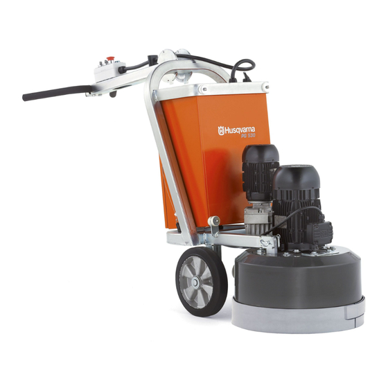
Components – orientation 4.Components – orientation Components 1. Handle bars 2. Control panel 3. Handle bar release 4. Handle bar adjuster 5. Hour counter 6. Electrical power connector 7. Electrical cabinet 8. Chassis / frame 9. Planetary head motor 10. Grinding/satellite heads motor 11. -
Page 10: Dismantling Into Basic Modules
Dismantling into basic modules 5.Dismantling into basic modules Basic modules This chapter shows how the machine is built up of basic modules, for example, the chassis / frame unit and the grinding unit and how the latter is set up in a service rack. The purpose is to illustrate how you can easily and effectively dismantle and assemble the machine in its basic modules. - Page 11 Dismantling into basic modules THE COVER / SHROUD The cover / shroud protects the interior from dirt and the user from moving parts. It is fitted with high precision and a tight seal to ensure a clean environment for the gear sprockets and other moving parts.
- Page 12 Dismantling into basic modules MOUNTING THE GRINDING UNIT IN A SERVICE RACK The grinding unit is a complex piece of technology and requires various types of high precision service. This is most easily done if the unit is mounted in a service rack in which the grinding unit can be tilted around and fixed in an ergonomic posi- tion.
-
Page 13: Removing The Satellite Heads
Removing the satellite heads 6.Removing the satellite heads The satellite heads Secure the diamond tools while in operation. Must be in good condition to ensure a smooth floor when grinding. 1. Remove the M16 centre bolt from each of the three satellite heads. •... -
Page 14: Opening Belt Compartment
Opening belt compartment 7.Opening belt compartment ×2 30mm The belt drive compartment Before proceeding with opening up the belt compartment; remove the satellite heads as described in the previous chapter. 1. Unclamp unit from cradle. • This step is necessary when opening up the belt compartment. -
Page 15: Removing Belt Parts And Satellite Motor
Removing belt parts and satellite motor 8.Removing belt parts and satellite motor The belt drive compartment Before proceeding with cleaning up the belt compartment; open up the belt compart- ment as described in the previous chapter. Always check that the machine is secured in the cradle before turning! REMOVE THE SATELLITE MOTOR 1. - Page 16 Removing belt parts and satellite motor REMOVE THE MOTOR MOUNTING PLATE 1. Tilt the cradle 180° (the opening upwards) and secure it with a corner pin. • Remove the cir-clip that holds the motor mounting plate shaft (a). • Place a board under the cradle to catch the motor mounting plate (3a). 2.
-
Page 17: Fitting In Internal Components
Fitting in internal components 9.Fitting in internal components Assembling Before assembling or applying silicone sealing, thread lock compound or lubricants, all the parts should be well cleaned with a solvent. Use compressed air to remove fine particles and dust. MOUNT THE BEARING HOUSING 1. - Page 18 Fitting in internal components ATTACH THE MOTOR PLATE 11. Use a soft mallet to knock down the motor plate shaft (d). • Knock until the seal reaches the main bearing hous- ing. 12. From underneath; fit on the cir-clip to secure the mo- tor mounting plate shaft (d).
-
Page 19: Pulley Service
Pulley service 10.Pulley service Assembling Before assembling or applying bearing adhes- Fly pulley ive compound or lubricants, all the parts should be well cleaned with a solvent. Use compressed air to remove particles and dust. Fly pulley - disassembled FLY PULLEY ASSEMBLY Fit bearing into bearing housing 1. - Page 20 Pulley service Fit fly pulley shaft through fly pulley Apply a layer of bearing retainer compound to the contact surfaces: (a) The inside of the fly pulley (1). (b) The end of the fly pulley shaft featur- ing a key (2). 1.
- Page 21 Pulley service Idle pulley Assembling Before assembling or applying bearing retain- er compound or lubricants, all the parts should be well cleaned with a solvent. Use compressed air to remove particles and dust. Idle pulley - disassembled IDLE/BELT TENSIONING PULLEY ASSEMBLY Fit bearing into idle pulley 1.
-
Page 22: Testing Motor Shaft Alignment
Testing motor shaft alignment 11.Testing motor shaf t alignment Motor shaft alignment To test the alignment of the motor shaft, the centre drive pulley should be mounted reversing the motion of picture 5 below (aligning key and keyway). Use a soft mallet to knock the centre drive pulley assembly (b) fully down on the motor shaft and tighten its bolt. - Page 23 Testing motor shaft alignment Aligning the planetary motor shaft The principal reason for misalignment are the contact surfaces between the motor shaft and the bore of the centre drive pulley. 1. The picture exaggerates a misaligned fit of the centre drive pulley to illustrate the need to clean or adjust the contact surfaces.
-
Page 24: Fitting On Satellite Motor And Pulleys
Fitting on satellite motor and pulleys 12.Fitting on satellite motor and pulleys Assembling the satellite motor and pulleys Be careful to attach the machine to the cradle (1). Clean all parts well with a solvent. Use grease as lubricator and threadlock (medium). Use silicone sealing compound to protect internal parts from dust and water. - Page 25 Fitting on satellite motor and pulleys FITTING THE FLY PULLEY ASSEMBLIES Use a high temperature grease as bearing lubricator. 1. Apply a thin layer of grease to the con- tact surfaces: (a) Around the bearing outside. (b) Inside the cast pulley bearing hous- ing.
-
Page 26: Setting Up A New Belt
Setting up a new belt 13.Setting up a new belt First time? If you are performing this task for the first time, it is highly recommended that you do a “dry” belt setup – skip all silicone sealing or thread-lock and make sure that you control the process –... - Page 27 Setting up a new belt SILICONE SEALING AND THREAD LOCK If you have never performed a belt replacement before, please make a dry setup first, and then redo the process from this point. 1. Add the following before proceeding: (a) Thread lock to the idle pulley shaft and the space shaft holes.
- Page 28 Setting up a new belt Mount the satellite shaft plates 1. Fit on the plates, aligning the screw holes: • The three bottom bearing plates. • And on top, the three bottom bearing cover plates. 2. Fit in the four bolts with washers for each satellite shaft plate assembly.
- Page 29 Setting up a new belt Tracking the belt It is necessary that the belt is properly balanced and set to run in its accurate position, to assure maximum reliability and performance of the machine. It is important to balance the belt so that it stays well centred on the pulleys, in both directions of operation.
- Page 30 Setting up a new belt Sealing the inspection/service holes When fitting on the last inspection and service holes, be sure to seal everything up properly with a silicone seal compound. Smoothing excessive silicone will make it easier to clean and inspect the machine. SEALING THE INSPECTION HOLES 1.
-
Page 31: Mounting The Satellite Heads
Mounting the satellite heads 14.Mounting the satellite heads Head boss The satellite heads are attached to the shafts by means of the head boss with four loc- ating dowel pins and a centre bolt. MOUNTING THE SATELLITE HEADS 1. Fit the V60 dust seal ring on the three head bosses. -
Page 32: Planetary Seal Installation
Planetary seal installation 15.Planetary seal installation Replace the planetary seal The planetary seal should seal the gap between the cover and the side wall. No dust should reach the chain ring. If the chain ring is dirty, the seal should be replaced. The planetary seal can be fitted with or without the chain ring in place. -
Page 33: Planetary Motor Gearbox
Planetary motor gearbox 16.Planetary motor gearbox Maintenance work The gear box assembly should be checked on a regular basis. (The pictures here (1—11+13) show the motor gearbox of the PG680 which has a larger sprocket, but the same principles apply). REMOVE THE GEAR BOX 1. -
Page 34: Mounting The Planetary Motor
Mounting the planetary motor 17.Mounting the planetary motor Chain ring and sprocket The power from the planetary motor is transmitted to the main planetary head by means of a shaft and sprocket to a chain ring. THE CHAIN RING 1. Lower the chain ring over the motor. 2. - Page 35 Mounting the planetary motor Optimising sprocket pressure to chain ring The motor attachment procedure as described here will ensure best possible power transmission, while maintaining a minimum of wear and friction. The process of tightening the satellite motor while running “loose”, will ensure an efficient adjustment of the sprockets into the chain ring.
-
Page 36: Tools
Tools ● = Service action 18.Tools Tools – supplied Assembly Rack Includes; rack and cradles for LIFTING TOOLS 530/680/820, clamps, lifting strap, Art. no. 5101527—01 2 D-shackles Lifting strap 5101449—01 Service-rack ● For hoisting machine (with cradle 5054636—01 clamped on), to and from the ser- vice rack. - Page 37 Tools ● = Service action RECOMMENDED TOOLS – NOT SUPPLIED PRESS TOOLS Bearing puller (smaller) 1. Fly pulley support block 5101457—01 ● Used for pulley service ● Used to house all fly pulleys Width: 100mm whenever work is done involving a (Chapter 9—10) press to prevent warping or mis- alignment of fly pulleys.
- Page 38 www.husqvarnacp.com English 2008-09 115 11 93-26...