Table of Contents
Advertisement
Quick Links
Advertisement
Table of Contents

Related Manuals for Mitsubishi Electric MELSEC-F FX3U-J1939


Summary of Contents for Mitsubishi Electric MELSEC-F FX3U-J1939
- Page 1 -J1939 USER'S MANUAL...
- Page 3 Safety Precautions (Read these precautions before use.) Before installation, operation, maintenance or inspection of this product, thoroughly read through and understand this manual and all of the associated manuals. Also, take care to handle the module properly and safely. This manual classifies the safety precautions into two categories: Indicates that incorrect handling may cause hazardous conditions, resulting in death or severe injury.
- Page 4 Safety Precautions (Read these precautions before use.) Reference • Make sure to observe the following precautions in order to prevent any damage to the machinery or accidents due to abnormal data written to the PLC under the influence of noise: 1) Do not bundle the main circuit line together with or lay it close to the main circuit, high-voltage line or load line.
- Page 5 • Do not disassemble or modify the PLC. Doing so may cause fire, equipment failures, or malfunctions. For repair, contact your local Mitsubishi Electric representative. • Turn off the power to the PLC before connecting or disconnecting any extension cable.
- Page 6 Safety Precautions (Read these precautions before use.) 5. DISPOSAL PRECAUTIONS Reference • Please contact a certified electronic waste disposal company for the environmentally safe recycling and disposal of your device. 6. TRANSPORTATION AND STORAGE PRECAUTIONS Reference • The PLC is a precision instrument. During transportation, avoid impacts larger than those specified in the general specifications of the PLC main unit manual by using dedicated packaging boxes and shock-absorbing palettes.
- Page 7 Précautions de Sécurité (Lire ces précautions avant toute utilisation.) Avant l’installation, l’utilisation, la maintenance ou le contrôle de ce produit, lisez entièrement ce manuel ainsi que tous les manuels associés et veillez à bien en comprendre le contenu. Aussi, assurez-vous de manipuler correctement et en toute sécurité...
- Page 8 Précautions de Sécurité (Lire ces précautions avant toute utilisation.) Référence • Assurez-vous d'observer les précautions suivantes afin d'éviter tous les endommagements aux machines ou les accidents dus aux données anormales écrites sur le contrôleur programmable sous les effets du bruit : 1) Ne pas regrouper la ligne du circuit principal, ou ne pas la placer près du circuit principal, de la ligne de haute tension ou de la ligne de charge.
- Page 9 Précautions de Sécurité (Lire ces précautions avant toute utilisation.) 3. PRÉCAUTIONS DE CABLAGE Référence • Assurez-vous de couper toutes les phases de l'alimentation externe avant d’essayer l'installation ou le câblage. Faute de quoi, il y a risque d'électrocution ou d'endommagement du produit. Référence •...
- Page 10 Ne pas démonter ni modifier le contrôleur programmable. Cela pourrait causer un départ de feu, une panne ou un dysfonctionnement des équipements. Pour réparation, contactez votre représentant local de Mitsubishi Electric. • Coupez l’alimentation du contrôleur programmable avant de connecter ou déconnecter les câbles d'extension.
-
Page 11: Safety Precautions
This manual confers no industrial property rights or any rights of any other kind, nor does it confer any patent licenses. Mitsubishi Electric Corporation cannot be held responsible for any problems involving industrial property rights which may occur as a result of using the contents noted in this manual. © 2012 MITSUBISHI ELECTRIC CORPORATION... - Page 12 • Since the examples within this manual, technical bulletin, catalog, etc. are used as reference; please use it after confirming the function and safety of the equipment and system. Mitsubishi Electric will not accept responsibility for actual use of the product based on these illustrative examples.
-
Page 13: Table Of Contents
-J1939 User's Manual Table of Contents Table of Contents SAFETY PRECAUTIONS ....................(1) Standards........................... 6 Certification of UL, cUL standards ....................... 6 Compliance with EC directive (CE Marking) ..................6 Associated Manuals........................8 Generic Names and Abbreviations Used in the Manual ............10 Reading the Manual ........................ - Page 14 -J1939 User's Manual Table of Contents 5. Allocation of Buffer Memories 5.1 Buffer Memories (BFM) Lists ......................32 5.2 How to Read/Write from/to Buffer Memory ................... 34 5.3 [BFM #20] Data Exchange Control ....................35 5.4 [BFM #21] Function Mode......................35 5.5 [BFM #22] Save/Restore Configuration ..................
- Page 15 -J1939 User's Manual Table of Contents 9. Command Interface 9.1 [BFM #1000 to #1066] Command Interface (CIF) ................ 72 9.2 Sending Layer 2 Message ......................73 9.3 Send PGN ............................. 74 9.4 Request PGN ..........................75 9.5 Setup PLC RUN>STOP Messages....................76 9.6 Reset Command Interface ......................
-
Page 16: Standards
-J1939 User's Manual Standards Standards Certification of UL, cUL standards -J1939 units comply with the UL standards (UL, cUL). UL, cUL File number :E95239 Regarding the standards that comply with the main unit, please refer to either the FX series product catalog or consult with your nearest Mitsubishi product provider. - Page 17 -J1939 User's Manual Standards Caution for Compliance with EC Directive 1) Caution for wiring For noise prevention, please ground at least 35 mm (1.38") of the twisted-pair cable along the grounding plate to which the ground terminal is connected. For details regarding wiring, refer to Section 4.2 2) Installation in Enclosure For details regarding installation in an enclosure of FX Series PLC,...
-
Page 18: Associated Manuals
-J1939 User's Manual Associated Manuals Associated Manuals Only the installation manual is packed together with the FX -J1939 Communication Block. For a detailed explanation of the FX -J1939, refer to this manual. For further information of the hardware information and instructions on the PLC main unit/CPU Module, refer to the respective manuals. - Page 19 -J1939 User's Manual Associated Manuals Document Title of manual Description Model code number FX5U PLCs CPU Module Describes FX5U PLC specification for I/O, wiring and installation extracted from the FX5U PLC from MELSEC Supplied MELSEC iQ-F FX5U CPU JY997D53401 iQ-F FX5U User's Manual (Hardware). Manual Module Hardware Manual For details, refer to FX5U PLC from MELSEC iQ-F...
-
Page 20: Generic Names And Abbreviations Used In The Manual
-J1939 User's Manual Generic Names and Abbreviations Used in the Manual Generic Names and Abbreviations Used in the Manual Generic name or abbreviation Description series Generic name for FX Series PLC PLC or main unit Generic name for FX Series PLC main unit series Generic name for FX Series PLC... - Page 21 -J1939 User's Manual Generic Names and Abbreviations Used in the Manual Generic name or abbreviation Description Manual Hardware Edition Abbreviation of FX Series User's Manual - Hardware Edition Hardware Edition Abbreviation of FX Series User's Manual - Hardware Edition Hardware Edition Abbreviation of FX Series User's Manual - Hardware Edition Hardware Edition...
-
Page 22: Reading The Manual
-J1939 User's Manual Reading the Manual Reading the Manual Indexes the chapter number. Shows the title of the chapter and the title Shows the manual title. of the section. The right side of each page This area shows the indexes the chapter number manual title for the current This area shows the title of the chapter and the for the page currently opened. -
Page 23: Introduction
• Avant d'utiliser ce produit pour des applications spéciales comme par exemple dans le domaine de l’énergie nucléaire, de l'énergie électrique, de l'aérospatiale, de la médecine ou du transport de passagers, veuillez consulter le représentant de Mitsubishi Electric. • Ce produit a été fabriqué sous un contrôle de qualité rigoureux. Cependant, lors de l'installation du produit où des accidents ou des pertes majeurs pourraient survenir si le produit échoue, installez des fonctions de sauvegarde ou de sécurité... - Page 24 1 Introduction -J1939 User's Manual 1.1 Outline 3. Support a Command Interface (CIF) The command interface is a tool to execute asynchronous network services, module configuration and diagnosis features. The following table shows the supported functions. Function Mode Selection Layer 2 Layer 2 J1939 Command...
-
Page 25: External Dimensions And Each Part Name
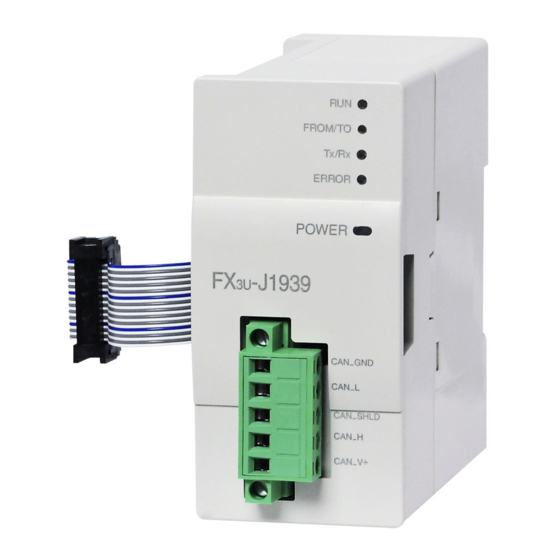
1 Introduction -J1939 User's Manual 1.2 External Dimensions and Each Part Name External Dimensions and Each Part Name 1.2.1 External dimensions and each part name Unit : mm (inches) 4.5 mounting holes 9 (0.36") 4 (0.16") 87 (3.43") 43 (1.7") (0.32") Mass (Weight): Approx. -
Page 26: Power And Status Leds
1 Introduction -J1939 User's Manual 1.2 External Dimensions and Each Part Name 1.2.2 Power and status LEDs LED Name LED Color Status Description Module is offline. Green Module is online. PLC is not accessing BFMs in module. FROM/TO Green PLC is accessing BFMs in module. Module is not transmitting or receiving messages. -
Page 27: System Configuration
1 Introduction -J1939 User's Manual 1.3 System Configuration System Configuration 1.3.1 General configuration CAN bus network Node 1 Node 3 Node 5 Terminating Terminating resistor resistor Node 2 Node 4 Node 6 -J1939 Communication block FX5U/FX5UC PLC Part Name Model Name Remarks Communication block -J1939... -
Page 28: Connection With Plc
1 Introduction -J1939 User's Manual 1.3 System Configuration 1.3.3 Connection with PLC The FX -J1939 connects with a PLC via an extension cable. The FX -J1939 is handled as a special extension block of the PLC. The unit number of the FX -J1939 is *1*2 automatically assigned No. -
Page 29: System Start-Up Procedure
1 Introduction -J1939 User's Manual 1.4 System Start-up Procedure System Start-up Procedure -J1939 Refer to Chapter 1 Outline of system: Outline Applicable PLC Refer to Chapter 2 Specifications: Check of specifications Operation environment Power supply specifications Performance specifications - Maximum bus length (depends on baud rate) Refer to Chapter 1 and 2 System configuration: System configuration... -
Page 30: Specifications
2 Specifications -J1939 User's Manual Specifications DESIGN PRECAUTIONS • Make sure to have the following safety circuits outside of the PLC to ensure safe system operation even during external power supply problems or PLC failure. Otherwise, malfunctions may cause serious accidents. 1) Most importantly, have the following: an emergency stop circuit, a protection circuit, an interlock circuit for opposite movements (such as normal vs. - Page 31 2 Specifications -J1939 User's Manual PRÉCAUTIONS DE CONCEPTION • Assurez-vous de configurer les circuits de sécurité suivants en dehors du contrôleur programmable afin d’assurer un fonctionnement sûr du système même pendant qu’il y a un problème d'alimentation externe ou une panne du contrôleur programmable. Faute de quoi, des dysfonctionnements peuvent causer des accidents graves.
-
Page 32: General Specifications
2 Specifications -J1939 User's Manual 2.1 General Specifications General Specifications Items other than the following table are equivalent to those of the PLC main unit/CPU Module. For further information of general specifications, refer to the manual of the PLC main unit/CPU Module. Refer to FX Hardware Edition Refer to FX... -
Page 33: Installation
3 Installation -J1939 User's Manual Installation INSTALLATION PRECAUTIONS • Make sure to cut off all phases of the power supply externally before attempting installation or wiring work. Failure to do so may cause electric shock or damage to the product. INSTALLATION PRECAUTIONS •... -
Page 34: Connection With Plc
3 Installation -J1939 User's Manual 3.1 Connection with PLC Connection with PLC The FX -J1939 connects on the right side of a PLC main unit/CPU Module or extension units/blocks (including special function units/blocks). For connection to an FX Series PLC or FX Series PLC extension block, an FX -CNV-IF or -1PS-5V is required. -
Page 35: Mounting
3 Installation -J1939 User's Manual 3.2 Mounting Mounting The FX -J1939 may be installed in a control cabinet with a 35 mm wide DIN46277 DIN rail mounting or M4 screw direct mounting. 3.2.1 DIN rail mounting The product may be mounted on a 35 mm wide DIN46277 (DIN rail). Fit the upper edge (A in the figure to the right) of the DIN rail mounting groove onto the DIN rail. -
Page 36: Direct Mounting
3 Installation -J1939 User's Manual 3.2 Mounting 3.2.2 Direct Mounting The product can be installed directly with screws. An interval space of 1 to 2 mm (0.04" to 0.08") between each unit is necessary. For further information of installation, refer to the following respective PLC manual. For mounting hole pitches, refer to Section 1.2 Refer to FX Hardware Edition... -
Page 37: Wiring
4 Wiring -J1939 User's Manual Wiring WIRING PRECAUTIONS • Make sure to cut off all phases of the power supply externally before attempting installation or wiring work. Failure to do so may cause electric shock or damage to the product. WIRING PRECAUTIONS •... -
Page 38: Applicable Cable And Connector
4 Wiring -J1939 User's Manual 4.1 Applicable Cable and Connector PRÉCAUTIONS DE CABLAGE • Assurez-vous de couper toutes les phases de l'alimentation externe avant d’essayer l'installation ou le câblage. Faute de quoi, il y a risque d'électrocution ou d'endommagement du produit. PRÉCAUTIONS DE CABLAGE •... -
Page 39: Applicable Cable
4 Wiring -J1939 User's Manual 4.1 Applicable Cable and Connector 4.1.2 Applicable cable Applicable Cable Item SAE J1939-11, CAN (Layer 2) SAE J1939-15 Cable Type Twisted pair cable Unshielded/ Shielded Shielded Unshielded No. of Pairs 2 pair Conformance Standard ISO 11898/1993 Wire Size 0.3 mm to 0.82 mm... -
Page 40: Can-Bus Wiring
4 Wiring -J1939 User's Manual 4.2 CAN-Bus Wiring CAN-Bus Wiring 4.2.1 Connecting communication cables (1) CAN_GND (1) CAN_GND (1) CAN_GND Terminating Terminating (2) CAN_L (2) CAN_L (2) CAN_L resistor resistor (3) CAN_SHLD (3) CAN_SHLD (3) CAN_SHLD (4) CAN_H (4) CAN_H (4) CAN_H (5) CAN_V+ (5) CAN_V+... -
Page 41: Grounding Of Twisted Pair Cable
4 Wiring -J1939 User's Manual 4.3 Grounding 4.2.3 Grounding of twisted pair cable Strip a part of the coating of the shielded twisted pair cable as shown below, and ground at least 35 mm (1.38") of the exposed shield section. Shielded twisted pair cable Shield 4.2.4... -
Page 42: Allocation Of Buffer Memories
5 Allocation of Buffer Memories -J1939 User's Manual 5.1 Buffer Memories (BFM) Lists Allocation of Buffer Memories Buffer Memories (BFM) Lists Caution • Do not access buffer memory (BFM) that is marked as "not used" (Ex. BFM #0 to #19, #23, #31 to #34, #49 to #99, #400, #480 to #499, etc.) by FROM/TO instructions, etc. - Page 43 5 Allocation of Buffer Memories -J1939 User's Manual 5.1 Buffer Memories (BFM) Lists Stored to Default Read/ BFM No. Description Flash Reference value Write BFM #974 to #999 Not used BFM #1000 to #1066 Command interface Chapter 9 BFM #1067 to #1099 Not used BFM #1100 to #1267 Pre-defined Layer 2 message configuration...
-
Page 44: How To Read/Write From/To Buffer Memory
5 Allocation of Buffer Memories -J1939 User's Manual 5.2 How to Read/Write from/to Buffer Memory How to Read/Write from/to Buffer Memory To read/write from/to buffer memory in the FX -J1939, use the FROM/TO instructions or the applied instructions that directly specify the buffer memory. /FX5U/FX5UC PLC applicable software is required to perform direct specification of the buffer memory and bit specification of word devices. -
Page 45: Bfm #20] Data Exchange Control
5 Allocation of Buffer Memories -J1939 User's Manual 5.3 [BFM #20] Data Exchange Control [BFM #20] Data Exchange Control This flag is used when data consistency is required for data exchange between data area in BFM #100 to #399 and BFM #1300 to #1799. Description Data consistency flag;... -
Page 46: Bfm #22] Save/Restore Configuration
5 Allocation of Buffer Memories -J1939 User's Manual 5.5 [BFM #22] Save/Restore Configuration [BFM #22] Save/Restore Configuration This BFM supports three bits that allow the default configuration of the BFMs to be restored and the configuration from BFMs to be stored into Flash ROM. Caution To prevent accidental destruction of the built-in Flash ROM, bit 0 is held ON for 1 s after the save operation is completed. -
Page 47: Bfm #24] Baud Rate
5 Allocation of Buffer Memories -J1939 User's Manual 5.6 [BFM #24] Baud Rate [BFM #24] Baud Rate Determines the communication speed (baud rate) of the module to the CAN bus. Baud rate change becomes effective after reset or power cycle. Caution Any new valid value written to BFM #21, #24, #25 bit 2, #26 or #27 is automatically stored to flash ROM. -
Page 48: Bfm #26] From/To Watchdog
5 Allocation of Buffer Memories -J1939 User's Manual 5.8 [BFM #26] FROM/TO Watchdog Access FROM (Read Access) TO (Write Access) OFF: Request configuration mode Bit 4 Request online mode Bit 5, 6 Not used Bit 7 Not used Module initialization state Bit 8 to 15 Not used If the arbitrary address capability is activated (BFM #25 bit 2 = ON) and the address set in BFM #27/... -
Page 49: Bfm #27] Node Address (Address Claim Start Address)
5 Allocation of Buffer Memories -J1939 User's Manual 5.9 [BFM #27] Node Address (Address Claim Start Address) [BFM #27] Node Address (Address Claim Start Address) Sets the node address within the J1939 network. A node address written by a TO instruction, etc. into BFM #27 will be effective after the next power cycle or BFM #25 bit 0 reset. - Page 50 5 Allocation of Buffer Memories -J1939 User's Manual 5.9 [BFM #27] Node Address (Address Claim Start Address) Setting Value State of BFM #25 bit 2 description When the current address of the FX -J1939 (displayed in BFM #28) is claimed by a node with a higher priority, the FX -J1939 will claim the next higher address.
-
Page 51: Bfm #28] Node Address (Current Address)
5 Allocation of Buffer Memories -J1939 User's Manual 5.10 [BFM #28] Node Address (Current Address) 5.10 [BFM #28] Node Address (Current Address) BFM #28 displays the current node address of the FX -J1939. Until the FX -J1939 is successfully able to claim an address, BFM #28 shows K254 (HFE). -
Page 52: Bfm #39] Bfm Setting Error Display
5 Allocation of Buffer Memories -J1939 User's Manual 5.16 [BFM #39] BFM Setting Error Display 5.16 [BFM #39] BFM Setting Error Display BFM #29 bit 6 is set to ON if an attempt to write an invalid value into a Buffer Memory is detected. BFM #39 displays the address of the target BFM of the invalid write attempt. -
Page 53: Bfm #100 To #399] Send/Receive Data Buffer
5 Allocation of Buffer Memories -J1939 User's Manual 5.18 [BFM #100 to #399] Send/Receive Data Buffer Manufacturer Code The manufacturer code identifies the maker of the ECU. The manufacturer code is assigned by the SAE and listed in the SAE J1939 main specification. Identity Number The Identity number is a unique code that distinguishes ECUs of the same Manufacturer and Kind (Industry Group, Vehicle System, Vehicle System Instance, Function, Function Instance, ECU instance and... - Page 54 5 Allocation of Buffer Memories -J1939 User's Manual 5.19 [BFM #401 to #479] Message Specific Error Code List Message specific error codes: Error Code Description H0000 No error Multi message transmission aborted by remote node. H10nn -J1939 received a connection abort message from remote node, the low-byte shows the abort cause. For abort cause, refer to documentation of remote node or applicable J1939 specification Multi message transmission aborted by local node.
-
Page 55: Bfm #1280 To #1284] Manual Transmit Trigger Flags
5 Allocation of Buffer Memories -J1939 User's Manual 5.20 [BFM #1280 to #1284] Manual Transmit Trigger flags 5.20 [BFM #1280 to #1284] Manual Transmit Trigger flags The transmission of a message in J1939 or Layer 2 mode can be triggered via the following flags. Transmit requests on receive messages are discarded. -
Page 56: Bfm #3000 To #3879] Configuration Of Remote Address To Ecu Name Assignment
5 Allocation of Buffer Memories -J1939 User's Manual 5.22 [BFM #3000 to #3879] Configuration of Remote Address to ECU Name Assignment 5.22 [BFM #3000 to #3879] Configuration of Remote Address to ECU Name Assignment When the remote nodes of a J1939 network support dynamic address allocation, it is possible that a remote node changes its current node address due to an address conflict. - Page 57 5 Allocation of Buffer Memories -J1939 User's Manual 5.22 [BFM #3000 to #3879] Configuration of Remote Address to ECU Name Assignment BFM No. Description Bit Length Default Value Remote ECU BFM #3869 8 bit K-1 (Not used) Node address BFM #3870 Arbitrary address capable field 1 bit BFM #3871...
-
Page 58: J1939 Communication Mode
6 J1939 Communication Mode -J1939 User's Manual 6.1 Send/Receive Data Buffer J1939 Communication Mode Send/Receive Data Buffer The FX -J1939 supports 75 standard messages (with up to 8 bytes) and 4 extended messages (with up to 250 bytes). It is also possible to combine several standard messages for data packages up to 250 bytes. 6.1.1 [BFM #100 to #399] Send/receive data buffer for standard messages These BFMs are used to buffer network data. -
Page 59: Bfm #1300 To #1799] Send/Receive Data Buffer For Extended Messages
6 J1939 Communication Mode -J1939 User's Manual 6.2 [BFM #500 to #973] Configuration Area 6.1.2 [BFM #1300 to #1799] Send/receive data buffer for extended messages These BFMs are used to buffer network data. For details, see the manual of the source/target module or the corresponding J1939 specification ... - Page 60 6 J1939 Communication Mode -J1939 User's Manual 6.2 [BFM #500 to #973] Configuration Area Description Default BFM No. Assigned Data BFM Value (Transmit Data Parameter Settings) (Receive Data Parameter Settings) BFM #938, PGN bit 17 to 0 Filter PGN bit 17 to 0 HFFFFFFFF #939 (includes Destination Address)
- Page 61 6 J1939 Communication Mode -J1939 User's Manual 6.2 [BFM #500 to #973] Configuration Area 1. PGN bit 17 to 0 (include Destination Address) PGN to be transmitted is specified by the lower 18 bits (bit 0 to 17) as shown below. The PGN must also include the Destination Address if applicable.
- Page 62 6 J1939 Communication Mode -J1939 User's Manual 6.2 [BFM #500 to #973] Configuration Area - Overview Tx Message valid and invalid settings Format Destination Mode Description BFM #27 Setting Invalid Setting Valid (Transmit Broadcast messages) PDU1 0 to 250 J1939 Any other address communication Setting Valid...
- Page 63 6 J1939 Communication Mode -J1939 User's Manual 6.2 [BFM #500 to #973] Configuration Area 3. ttype (transmission type) The transmission type defines the trigger for messages to be sent on the network. All configured transmit messages will be sent when the module is set from configuration to online mode. After this first transmission, the message will be sent every time the condition of the selected transmission type is satisfied.
- Page 64 6 J1939 Communication Mode -J1939 User's Manual 6.2 [BFM #500 to #973] Configuration Area Remote transmission request The CAN standard defines a service to request certain information from the network. Upon reception of this kind of request, every node checks if it is the producer of the requested information. The producer node of the requested data will respond with the desired data.
- Page 65 6 J1939 Communication Mode -J1939 User's Manual 6.2 [BFM #500 to #973] Configuration Area Transmission Type K2 and K3 Transmission type K2 and K3 are time controlled. If the transmission was triggered by remote request or manual/PLC trigger, the interval timer is restarted, and the next transmission will be suspended for the set interval to avoid unnecessary data traffic caused by remote requests or manual triggers.
- Page 66 6 J1939 Communication Mode -J1939 User's Manual 6.2 [BFM #500 to #973] Configuration Area Transmission Type K4 Transmission type K4 will trigger the transmission only upon explicit request from the network or PLC/user trigger. 1) Transmission Type K4 (trigger via remote request frame) When the FX -J1939 receives a valid request frame for supported information, it will respond with the most recent internal data that is copied from the BFM every time BFM #20 bit 0 is set to ON.
- Page 67 6 J1939 Communication Mode -J1939 User's Manual 6.2 [BFM #500 to #973] Configuration Area 5. DLC (data length count) Set the number of bytes to be transmitted to 0 to 8 bytes for standard messages (single frame). For the last four settings (BFM #950 to #973), the DLC can be up to 250. Please keep in mind that the transmission/reception of this amount of data must be segmented and transferred in multiple CAN messages and should be used for non time critical data only (e.g.
-
Page 68: Example Configuration Setting For J1939 Communication Mode
6 J1939 Communication Mode -J1939 User's Manual 6.2 [BFM #500 to #973] Configuration Area 6.2.1 Example configuration setting for J1939 communication mode The configuration setting example of a message of 20 bytes which combines three standard 8 byte message buffers starting at message 4 is shown below. Transmit data parameter settings case: PGN bit 17 to 0 (includes Destination Address): K45364 (HB134) PGN = K45312 (HB100, "Proprietarily Configurable Message 1"),... -
Page 69: Example J1939 Communication Mode Use Of Run>Stop Messages And Remote Address To Ecu Name Assignment
6 J1939 Communication Mode -J1939 User's Manual 6.2 [BFM #500 to #973] Configuration Area 6.2.2 Example J1939 communication mode use of RUN>STOP messages and remote address to ECU name assignment These examples show the use of the RUN>STOP Messages in J1939 communication mode. Additionally, the function of the Remote Address to ECU Name assignment and its effect on user Messages and the RUN>STOP Messages is shown. - Page 70 6 J1939 Communication Mode -J1939 User's Manual 6.2 [BFM #500 to #973] Configuration Area Behaviour If Node “B” Sends Address BFM No. Configuration Effect Display in Online Configuration Claim for Address H89 BFM #506, HB280 No change: #507 RX Message !!The source must still be H88!! BFM #508 PGN HB280 with 8 data...
-
Page 71: Layer 2 Communication Mode (11/29 Bit Id)
7 Layer 2 Communication Mode (11/29 bit ID) -J1939 User's Manual 7.1 [BFM #100 to #399] Sending/Receiving Pre-defined Layer 2 Messages Layer 2 Communication Mode (11/29 bit ID) This chapter describes the data transfer locations and setting of the Layer 2 communication (11/29 bit ID) mode. - Page 72 7 Layer 2 Communication Mode (11/29 bit ID) -J1939 User's Manual 7.1 [BFM #100 to #399] Sending/Receiving Pre-defined Layer 2 Messages Description Message Initial Read/ Stored to BFM No. Name Value Write Flash ROM High Byte Low Byte BFM #387 11/29 bit CAN-ID low word HFFFF CAN-ID 42 LW...
- Page 73 7 Layer 2 Communication Mode (11/29 bit ID) -J1939 User's Manual 7.1 [BFM #100 to #399] Sending/Receiving Pre-defined Layer 2 Messages 2. When receiving messages The CAN-ID, status/control flags and data bytes of each message are as follows. Note In case more than one ID can pass the filter set in BFM #1100 to #1267, the received CAN-ID might change. The CAN-ID, DLC and data of the latest received message will always be displayed.
-
Page 74: Bfm #1100 To #1267] Pre-Defined Layer 2 Messages Parameter
7 Layer 2 Communication Mode (11/29 bit ID) -J1939 User's Manual 7.2 [BFM #1100 to #1267] Pre-defined Layer 2 Messages Parameter [BFM #1100 to #1267] Pre-defined Layer 2 Messages Parameter This section describes the Pre-defined Layer 2 messages configuration. The Layer 2 message parameter defines if the corresponding Layer 2 message in BFM #100 to #393 is a transmit or receive message, e.g. -
Page 75: Pre-Defined Layer 2 Transmit Messages
7 Layer 2 Communication Mode (11/29 bit ID) -J1939 User's Manual 7.2 [BFM #1100 to #1267] Pre-defined Layer 2 Messages Parameter 7.2.1 Pre-defined Layer 2 transmit messages This subsection describes parameters A to D for the transmit message. Parameter Description Default Value Layer 2 message number parameter A Constant HFFFF... - Page 76 7 Layer 2 Communication Mode (11/29 bit ID) -J1939 User's Manual 7.2 [BFM #1100 to #1267] Pre-defined Layer 2 Messages Parameter 2. Parameter C "transmission type" for each Layer 2 message The transmission type defines the transmit/receive message and transmission trigger event of the message as follows.
-
Page 77: Pre-Defined Layer 2 Receive Messages
7 Layer 2 Communication Mode (11/29 bit ID) -J1939 User's Manual 7.2 [BFM #1100 to #1267] Pre-defined Layer 2 Messages Parameter 7.2.2 Pre-defined Layer 2 receive messages This subsection describes parameters A to D for the receive message. Parameter Description Default Value Layer 2 message number parameter A Reception CAN-ID low word HFFFF... - Page 78 7 Layer 2 Communication Mode (11/29 bit ID) -J1939 User's Manual 7.2 [BFM #1100 to #1267] Pre-defined Layer 2 Messages Parameter Example 2: Layer 2 message 2 parameter A = H00000180 Layer 2 message 1 parameter C = H00000006 BFM #107 to #113 stores received messages with CAN-IDs H180, H182, H184 and H186 because the ID bits 1 and 2 are not evaluated.
-
Page 79: Bfm #1270 To #1272] Layer 2 Rtr Flags
7 Layer 2 Communication Mode (11/29 bit ID) -J1939 User's Manual 7.3 [BFM #1270 to #1272] Layer 2 RTR Flags [BFM #1270 to #1272] Layer 2 RTR Flags If the FX -J1939 is set to Layer 2 communication mode, an incoming RTR message is indicated in the BFM if the following conditions are satisfied: •... -
Page 80: Bfm #1900 To #1927] Plc Run>Stop Messages
8 [BFM #1900 to #1927] PLC RUN>STOP Messages -J1939 User's Manual [BFM #1900 to #1927] PLC RUN>STOP Messages -J1939 can transmit the message according to its state, if the PLC is in one of the following two states. Up to four transmit messages can each be registered. •... - Page 81 8 [BFM #1900 to #1927] PLC RUN>STOP Messages -J1939 User's Manual MEMO...
-
Page 82: Command Interface
9 Command Interface -J1939 User's Manual 9.1 [BFM #1000 to #1066] Command Interface (CIF) Command Interface This chapter describes the Command Interface supported by FX -J1939. A function overview of the Command Interface is shown in the following table. Function Mode Selection J1939 Layer 2 Layer 2... -
Page 83: Sending Layer 2 Message
9 Command Interface -J1939 User's Manual 9.2 Sending Layer 2 Message Sending Layer 2 Message If the FX -J1939 is set to Layer 2 communication Mode, this function can be used to send any Layer 2 message to the CAN bus. This command is prohibited in J1939 communication mode. -
Page 84: Send
9 Command Interface -J1939 User's Manual 9.3 Send PGN Send PGN This command can be used to transmit a J1939 message frame with a certain PGN and destination address. This command is prohibited in Layer 2 communication Mode. Description BFM No. TO (Write Access) FROM (Read Access) High Byte... -
Page 85: Request
9 Command Interface -J1939 User's Manual 9.4 Request PGN Request PGN This command can be used to request a J1939 message frame with a certain PGN from the network. This command is prohibited in Layer 2 communication Mode. This command is supported in the FX -J1939 firmware Ver. -
Page 86: Setup Plc Run>Stop Messages
9 Command Interface -J1939 User's Manual 9.5 Setup PLC RUN>STOP Messages Setup PLC RUN>STOP Messages This command can be used to set up the Layer 2 "PLC RUN>STOP messages" in a convenient way for the J1939 mode. The Message Buffers in BFM #1900 to #1927 are set up with the Layer 2 messages that result from the given Parameters and the actual node ID. -
Page 87: Reset Command Interface
9 Command Interface -J1939 User's Manual 9.6 Reset Command Interface Reset Command Interface This command can be used to reset the command interface and clear errors displayed in BFM #1000 to #1066. Description BFM No. TO (Write Access) FROM (Read Access) BFM #1000 Command: HFFFF (K-1) -
Page 88: Cif: Error Code List
9 Command Interface -J1939 User's Manual 9.8 CIF: Error code list CIF: Error code list If an error occurs during the execution of a command, the CIF will display these errors and no further commands will be accepted. To reset the CIF and clear the error, write HFFFF (K-1) to BFM #1000. While processing a command in CIF, FX -J1939 displays HFFFF in the read access area of BFM #1000. -
Page 89: 10. Communication Settings Procedure
Ne pas démonter ni modifier le contrôleur programmable. Cela pourrait causer un départ de feu, une panne ou un dysfonctionnement des équipements. Pour réparation, contactez votre représentant local de Mitsubishi Electric. • Coupez l’alimentation du contrôleur programmable avant de connecter ou déconnecter les câbles d'extension. -
Page 90: J1939 Communication Mode
10 Communication Settings Procedure -J1939 User's Manual 10.1 J1939 Communication Mode 10.1 J1939 Communication Mode When using J1939 Communication Mode, the outline of the communication setting procedure is as follows. For further information on BFMs, refer to Chapter 5 For further information on data transfer location and configuration, refer to Chapter 6 For further information on the CIF, refer to Chapter 9 ... -
Page 91: Layer 2 Communication (11/29 Bit Id) Mode
10 Communication Settings Procedure -J1939 User's Manual 10.2 Layer 2 communication (11/29 bit ID) mode 10.2 Layer 2 communication (11/29 bit ID) mode When using the 11 bit / 29 bit CAN-ID Layer 2 Mode, the outline of the communication setting procedure is as follows. -
Page 92: 11. Example Program
Ne pas démonter ni modifier le contrôleur programmable. Cela pourrait causer un départ de feu, une panne ou un dysfonctionnement des équipements. Pour réparation, contactez votre représentant local de Mitsubishi Electric. • Coupez l’alimentation du contrôleur programmable avant de connecter ou déconnecter les câbles d'extension. -
Page 93: System Configuration
11 Example Program -J1939 User's Manual 11.1 System Configuration The programs shown below are examples on how to set local parameters, set up a network and exchange data over the network with FX -J1939. 11.1 System Configuration The system consists of two FX -J1939 nodes, Node A and Node B. -
Page 94: J1939 Communication Example Programs
11 Example Program -J1939 User's Manual 11.3 J1939 Communication Example Programs 11.3 J1939 Communication Example Programs The example programs for J1939 communication between two FX -J1939 modules are written for GX Work2 (simple mode, no labels). 1. Node A program * ################################################################ * Set Special Function Block (SFB) address of FX3U-J1939 * ################################################################... - Page 95 11 Example Program -J1939 User's Manual 11.3 J1939 Communication Example Programs * <Reset required after mode change> M8000 <> K1939 Protocol monitor Mode address * <Refresh/read module status > FROM K4M0 Online/ address Offline * If module is online in first PLC cycle * set offline for configuration, bit 2 must not be changed * while bit 0 or 7 is ON * 1) Set offline, keep bit 2 ON...
- Page 96 11 Example Program -J1939 User's Manual 11.3 J1939 Communication Example Programs * ################################################################ * Message configuration * Message 1 (Configuration #500 to #505, Data #100 to #103) * Tx Message * PGN 45312 (HB100), destination 127 (H7F) * event oriented transmission type (ttype K1 >> on data change) * message priority (0 to 7, 6 default, 0 highest) * interval for time triggered messages (unused) set K100 = 1 sec.
- Page 97 11 Example Program -J1939 User's Manual 11.3 J1939 Communication Example Programs * ################################################################ * Set FX3U-J1939 online * ################################################################ * <Request online > Online/ Module Address Offline Init. Capable address State * <Request online > Address Capable address * ################################################################ * Set out data, read in data * ################################################################ * <Copy RTC data to message...
- Page 98 11 Example Program -J1939 User's Manual 11.3 J1939 Communication Example Programs 2. Node B program * ################################################################ * Set Special Function Block (SFB) address of FX3U-J1939 * ################################################################ * <Set SFB address > M8000 DMOV monitor address * ################################################################ * Initial setting * before any access to Configuration BFMs check: * BFM #25 bit 0 (online) and bit 7 (init.
- Page 99 11 Example Program -J1939 User's Manual 11.3 J1939 Communication Example Programs * <Reset required after mode change> M8000 <> K1939 Protocol monitor Mode address * <Refresh/read module status > FROM K4M0 Online/ address Offline * If module is online in first PLC cycle * set offline for configuration, bit 2 must not be changed * while bit 0 or 7 is ON * 1) Set offline, keep bit 2 ON...
- Page 100 11 Example Program -J1939 User's Manual 11.3 J1939 Communication Example Programs * ################################################################ * Message configuration * Message 1 (Configuration #500 to #505, Data #100 to #103) * Tx Message * PGN 45568 (HB200), destination 128 (H80) * event oriented transmission type (ttype K1 >> on data change) * message priority (0 to 7, 6 default, 0 highest) * interval for time triggered messages (unused) set K100 = 1 sec.
- Page 101 11 Example Program -J1939 User's Manual 11.3 J1939 Communication Example Programs * ################################################################ * Set FX3U-J1939 online * ################################################################ * <Request online > Online/ Module Address Offline Init. Capable address State * <Request online > Address Capable address * ################################################################ * Set out data, read in data * ################################################################ * <Copy RX data to TX...
-
Page 102: 12. Diagnostics
Ne pas démonter ni modifier le contrôleur programmable. Cela pourrait causer un départ de feu, une panne ou un dysfonctionnement des équipements. Pour réparation, contactez votre représentant local de Mitsubishi Electric. • Coupez l’alimentation du contrôleur programmable avant de connecter ou déconnecter les câbles d'extension. -
Page 103: Preliminary Checks
12 Diagnostics -J1939 User's Manual 12.1 Preliminary Checks 12.1 Preliminary Checks Check the RUN, FROM/TO, Tx/Rx, ERROR and POWER LED status. 1. RUN LED LED State Description -J1939 is in offline. -J1939 is in online. 2. FROM/TO LED LED State Description PLC is not accessing BFMs in FX -J1939. - Page 104 12 Diagnostics -J1939 User's Manual 12.1 Preliminary Checks 5. POWER LED LED State Description The power is being correctly supplied from FX /FX5U /FX5UC PLC via the extension cable to FX -J1939. The power is being incorrectly supplied from FX /FX5U /FX5UC PLC via the extension...
-
Page 105: Detail Error Check
If this error flag is not cleared after a module reset (BFM #25 bit 0) or another power cycle, FX Bit 2 error J1939 is probably damaged. Please contact your local Mitsubishi Electric representative. For module restart, refer to Section 5.7 The FX -J1939 is bus OFF. - Page 106 12 Diagnostics -J1939 User's Manual 12.2 Detail Error Check Description Action FROM/TO watchdog timer expired. Please see the above note. FROM/TO watchdog Bit 7 This error flag can be reset by writing to BFM #26. timer expired For the FROM/TO watchdog, refer to Section 5.8 Internal data queue overflowed.
-
Page 107: Warranty
-J1939 User's Manual Warranty Warranty Please confirm the following product warranty details before using this product. 1. Gratis Warranty Term and Gratis Warranty Range 2. Onerous repair term after discontinuation of If any faults or defects (hereinafter "Failure") found to be production the responsibility of Mitsubishi occurs during use of the Mitsubishi shall accept onerous product repairs for... -
Page 108: Revised History
-J1939 User's Manual Revised History Revised History Date Revision Description 5/2012 First Edition 3/2014 • Firmware version 1.10 is supported. ® • Description of NMEA 2000 is deleted. • The following error code is added: H12FF • The explanation of Configuration Area is modified. [Section 6.2] •... - Page 110 -J1939 USER'S MANUAL HEAD OFFICE: TOKYO BUILDING, 2-7-3 MARUNOUCHI, CHIYODA-KU, TOKYO 100-8310, JAPAN JY997D43101D Effective October 2017 (MEE) Specifications are subject to change without notice.