Fujitsu ARYG12LHTBP Design & Technical Manual
Hide thumbs
Also See for ARYG12LHTBP:
- Service manual (18 pages) ,
- Design & technical manual (144 pages)
Table of Contents
Advertisement
Quick Links
Advertisement
Table of Contents

Related Manuals for Fujitsu ARYG12LHTBP


Summary of Contents for Fujitsu ARYG12LHTBP
- Page 1 AIR CONDITIONER Duct type DESIGN & TECHNICAL MANUAL INDOOR ARYG12LHTBP ARYG18LHTBP ARYG36LHTBP ARYG14LHTBP ARYG24LHTBP ARYG45LHTBP ARYG30LHTBP ARYG54LHTBP OUTDOOR AOYG12LBLA AOYG18LBCA AOYG30LBTA AOYG45LBTA AOYG14LBLA AOYG24LBCA AOYG36LBTA AOYG54LBTA DR_AR006EF_05 2018.07.13...
- Page 2 Notices: • Product specifications and design are subject to change without notice for future improvement. • For further details, please check with our authorized dealer. Copyright © 2015, 2018 Fujitsu General Limited. All rights reserved.
-
Page 3: Table Of Contents
2-3. Models: ARYG36LHTBP, ARYG45LHTBP, and ARYG54LHTBP .........10 2-4. Installation space requirement ..................11 2-5. Maintenance space requirement..................12 3. Wiring diagrams ..................13 3-1. Models: ARYG12LHTBP, ARYG14LHTBP, ARYG18LHTBP, and ARYG24LHTBP ..13 3-2. Models: ARYG30LHTBP, ARYG36LHTBP, ARYG45LHTBP, and ARYG54LHTBP ..14 4. Capacity table....................15 4-1. Cooling capacity......................15 4-2. - Page 4 CONTENTS (continued) Part 2. OUTDOOR UNIT..............77 2-1. Specifications...................78 2. Dimensions....................82 2-1. Models: AOYG12LBLA and AOYG14LBLA ..............82 2-2. Models: AOYG18LBCA and AOYG24LBCA ..............83 2-3. Models: AOYG30LBTA and AOYG36LBTA..............84 2-4. Models: AOYG45LBTA and AOYG54LBTA..............85 3. Installation space ..................86 3-1. Models: AOYG12LBLA, AOYG14LBLA, AOYG18LBCA, and AOYG24LBCA ....86 3-2.
- Page 5 CONTENTS (continued) 8-6. Model: AOYG36LBTA....................111 8-7. Model: AOYG45LBTA....................111 8-8. Model: AOYG54LBTA....................111 9. Operation noise (sound pressure)............112 9-1. Noise level curve......................112 9-2. Sound level check point ....................116 10. Electrical characteristics ................117 11. Safety devices ...................118 12. External input and output (AOYG45LBTA and AOYG54LBTA) ..... 122 12-1.External input ......................122 12-2.External output......................124 13.
-
Page 7: Part 1. Indoor Unit
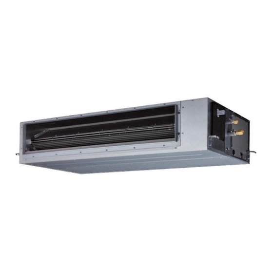
Part 1. INDOOR UNIT DUCT TYPE: ARYG12LHTBP ARYG14LHTBP ARYG18LHTBP ARYG24LHTBP ARYG30LHTBP ARYG36LHTBP ARYG45LHTBP ARYG54LHTBP... -
Page 8: Specifications
1. Specifications Duct Type Inverter heat pump Model name ARYG12LHTBP ARYG14LHTBP Power supply 230 V ~ 50 Hz Available voltage range 198—264 V Rated Btu/h 11,950 14,650 Cooling 0.9 — 4.4 0.9 — 5.4 Min.—Max. Btu/h 3,100 — 15,000 3,100 — 18,400... - Page 9 Model name ARYG12LHTBP ARYG14LHTBP Cooling Energy efficiency class Heating (Average) Cooling 3.5 (35°C) 4.3 (35°C) Pdesign Heating (Average) 4.2 (-10°C) 4.5 (-10°C) SEER Cooling 6.20 6.10 kWh/kWh SCOP Heating (Average) 4.10 4.00 Annual energy consumption kWh/a QHE (Average) 1,434 1,573...
- Page 10 Duct Type Inverter heat pump Model name ARYG18LHTBP ARYG24LHTBP ARYG30LHTBP Power supply 230 V ~ 50 Hz Available voltage range 198—264 V Rated Btu/h 17,700 23,200 29,000 Cooling 0.9 — 6.5 0.9 — 8.0 2.8—10.0 Min.—Max. Btu/h 3,100 — 22,200 3,100 —...
- Page 11 Model name ARYG18LHTBP ARYG24LHTBP ARYG30LHTBP Cooling Energy efficiency class Heating (Average) Cooling 5.2 (35°C) 6.8 (35°C) 8.5 (35°C) Pdesign Heating (Average) 4.3 (-10°C) 6.0 (-10°C) 8.0 (-10°C) SEER Cooling 7.15 6.50 5.95 kWh/kWh SCOP Heating (Average) 4.11 4.01 3.95 Annual energy consumption kWh/a QHE (Average) 1,462...
- Page 12 Duct Type Inverter heat pump Model name ARYG36LHTBP ARYG45LHTBP ARYG54LHTBP Power supply 230 V ~ 50 Hz Available voltage range 198—264 V 12.1 13.4 Rated Btu/h 32,100 41,300 45,700 Cooling 2.8—11.2 4.0—14.0 4.5 - 14.5 Min.—Max. Btu/h 9,500 - 38,200 13,700 - 47,800 15,400 - 49,500 Capacity...
- Page 13 Model name ARYG36LHTBP Cooling Energy efficiency class Heating (Average) Cooling 9.4 (35°C) Pdesign Heating (Average) 8.7 (-10°C) SEER Cooling 5.81 kWh/kWh SCOP Heating (Average) 3.81 Annual energy consumption kWh/a QHE (Average) 3,194 Cooling Sound power level HIGH dB (A) Heating - 7 - 1.
-
Page 14: Dimensions
2. Dimensions 2-1. Models: ARYG12LHTBP and ARYG14LHTBP Unit: mm Control box Gas pipe Drain port Liquid pipe Top view Side view (R) Side view (L) Front view Rear view - 8 - 2-1. Models: ARYG12LHTBP and ARYG14LHTBP 2. Dimensions... -
Page 15: Models: Aryg18Lhtbp, Aryg24Lhtbp, And Aryg30Lhtbp
2-2. Models: ARYG18LHTBP, ARYG24LHTBP, and ARYG30LHTBP Unit: mm Control box Gas pipe Drain port Liquid pipe Side view (R) Side view (L) Top view Front view Rear view - 9 - 2-2. Models: ARYG18LHTBP, ARYG24LHTBP, and ARYG30LHTBP 2. Dimensions... -
Page 16: Models: Aryg36Lhtbp, Aryg45Lhtbp, And Aryg54Lhtbp
2-3. Models: ARYG36LHTBP, ARYG45LHTBP, and ARYG54LHTBP Unit: mm 1,440 1,295 P100 × 12 = 1,200 Φ125 Control box Gas pipe Φ4 Liquid pipe Drain port P100 × 11 = 1,100 Φ4.5 1,162 1,400 Side view (L) Top view Side view (R) Φ4.5 Front view Rear view... -
Page 17: Installation Space Requirement
2-4. Installation space requirement Provide sufficient installation space for product safety. ¢ Models: ARYG12LHTBP, ARYG14LHTBP, ARYG18LHTBP, ARYG24LHTBP, ARYG30LHTBP, ARYG36LHTBP, ARYG45L- HTBP, and ARYG54LHTBP Unit: mm 20 or more 150 or more 300 or more 20 or more 2,500 or more... -
Page 18: Maintenance Space Requirement
For future maintenance and service access, provide sufficient maintenance space. NOTE: Do not place any wiring or illumination in the maintenance space, as they will impede ser- vice. ¢ Models: ARYG12LHTBP, ARYG14LHTBP, ARYG18LHTBP, ARYG24LHTBP, ARYG30LHTBP, ARYG36LHTBP, ARYG45L- HTBP, and ARYG54LHTBP •... -
Page 19: Wiring Diagrams
3. Wiring diagrams 3-1. Models: ARYG12LHTBP, ARYG14LHTBP, ARYG18LHTBP, and ARYG24LHTBP - 13 - 3-1. Models: ARYG12LHTBP, ARYG14LHTBP, ARYG18LHTBP, and ARYG24LHTBP 3. Wiring diagrams... -
Page 20: Models: Aryg30Lhtbp, Aryg36Lhtbp, Aryg45Lhtbp, And Aryg54Lhtbp
3-2. Models: ARYG30LHTBP, ARYG36LHTBP, ARYG45LHTBP, and ARYG54LHTBP - 14 - 3-2. Models: ARYG30LHTBP, ARYG36LHTBP, ARYG45LHTBP, and ARYG54LHTBP 3. Wiring diagrams... -
Page 21: Capacity Table
Airflow Rate (AFR): For cooling capacity: Total Capacity (TC), Sensible Heat Capacity (SHC), and Input Power (IP) For heating capacity: Total Capacity (TC) and Input Power (IP) 4-1. Cooling capacity ¢ Model: ARYG12LHTBP Indoor temperature °CDB °CWB °CDB... - Page 22 ¢ Model: ARYG24LHTBP 1,360 Indoor temperature °CDB °CWB °CDB 4.92 4.28 0.36 5.49 4.31 0.37 5.67 4.68 0.37 6.05 4.70 0.37 6.23 5.08 0.37 6.61 5.05 0.38 6.98 5.39 0.38 4.78 4.20 0.45 5.32 4.23 0.45 5.50 4.60 0.46 5.87 4.61 0.46 6.04...
- Page 23 ¢ Model: ARYG45LHTBP 2,550 Indoor temperature °CDB °CWB °CDB 10.22 8.77 2.08 11.37 8.83 2.11 11.76 9.59 2.13 12.54 9.62 2.14 12.93 10.39 2.16 13.70 10.35 2.18 14.47 11.03 2.20 10.30 8.91 2.00 11.47 8.96 2.03 11.86 9.74 2.04 12.65 9.78 2.06 13.04...
-
Page 24: Heating Capacity
4-2. Heating capacity NOTE: Values mentioned in the table are calculated based on the maximum capacity. ¢ Model: ARYG12LHTBP Indoor temperature °CDB °CDB °CWB 3.76 1.66 3.67 1.70 3.58 1.73 3.49 1.77 3.40 1.80 4.26 1.66 4.16 1.70 4.06 1.73 3.96... - Page 25 ¢ Model: ARYG30LHTBP 1,700 Indoor temperature °CDB °CDB °CWB 8.26 3.03 8.07 3.09 7.87 3.16 7.67 3.22 7.48 3.28 8.75 3.04 8.54 3.11 8.33 3.18 8.12 3.24 7.91 3.30 9.56 3.10 9.34 3.16 9.11 3.22 8.88 3.29 8.65 3.35 10.15 3.10 9.91 3.17...
-
Page 26: Fan Performance
5. Fan performance 5-1. Fan performance curve ¢ Model: ARYG12LHTBP Fan performance curve_1 Hi (SP mode20) SP mode20 upper limit SP mode20 lower limit Qu(SP mode20) Normal SP Hi (Normal SP) upper limit Normal SP Qu (Normal SP) lower limit... - Page 27 Characteristics of air volume and capacity • Cooling 1,000 1,500 2,000 [l/s] Airflow • Heating 1,000 1,500 2,000 [l/s] Airflow - 21 - 5-1. Fan performance curve 5. Fan performance...
- Page 28 ¢ Model: ARYG14LHTBP Fan performance curve_1 Hi (SP mode20) SP mode20 upper limit SP mode20 lower limit Qu(SP mode20) Normal SP upper limit Hi (Normal SP) Normal SP Qu (Normal SP) lower limit 1,000 1,500 2,000 [l/s] Airflow Fan performance curve_2 (For function setting by remote controller) Hi (SP mode19) Hi (SP mode20)
- Page 29 Characteristics of air volume and capacity • Cooling 1,000 1,500 2,000 [l/s] Airflow • Heating 1,000 1,500 2,000 [l/s] Airflow - 23 - 5-1. Fan performance curve 5. Fan performance...
- Page 30 ¢ Model: ARYG18LHTBP Fan performance curve_1 Hi (SP mode20) SP mode20 upper limit SP mode20 lower limit Qu(SP mode20) Normal SP Hi (Normal SP) upper limit Normal SP Qu (Normal SP) lower limit 1,000 1,500 2,000 [l/s] Airflow Fan performance curve_2 (For function setting by remote controller) Hi (SP mode19) Hi (SP mode20)
- Page 31 Characteristics of air volume and capacity • Cooling 1,000 1,500 2,000 [l/s] Airflow • Heating 1,000 1,500 2,000 [l/s] Airflow - 25 - 5-1. Fan performance curve 5. Fan performance...
- Page 32 ¢ Model: ARYG24LHTBP Fan performance curve_1 Hi (SP mode20) SP mode20 upper limit SP mode20 lower limit Qu(SP mode20) Normal SP Hi (Normal SP) upper limit Qu (Normal SP) Normal SP lower limit 1,000 1,500 2,000 2,500 [l/s] Airflow Fan performance curve_2 (For function setting by remote controller) Hi (SP mode19) Hi (SP mode20)
- Page 33 Characteristics of air volume and capacity • Cooling 1,000 1,500 2,000 2,500 [l/s] Airflow • Heating 1,000 1,500 2,000 2,500 [l/s] Airflow - 27 - 5-1. Fan performance curve 5. Fan performance...
- Page 34 ¢ Model: ARYG30LHTBP Fan performance curve_1 Hi (SP mode20) SP mode20 upper limit SP mode20 lower limit Qu(SP mode20) Normal SP Hi (Normal SP) upper limit Normal SP Qu (Normal SP) lower limit 1,000 1,500 2,000 2,500 [l/s] Airflow Fan performance curve_2 (For function setting by remote controller) Hi (SP mode19) Hi (SP mode20)
- Page 35 Characteristics of air volume and capacity • Cooling 1,000 1,500 2,000 2,500 [l/s] Airflow • Heating 1,000 1,500 2,000 2,500 [l/s] Airflow - 29 - 5-1. Fan performance curve 5. Fan performance...
- Page 36 ¢ Model: ARYG36LHTBP Fan performance curve_1 Hi (SP mode20) SP mode20 upper limit SP mode20 lower limit Normal SP Hi (Normal SP) Qu(SP mode20) upper limit Normal SP lower limit Qu (Normal SP) 1,000 1,500 2,000 2,500 3,000 [l/s] Airflow Fan performance curve_2 (For function setting by remote controller) Hi (SP mode19)
- Page 37 Characteristics of air volume and capacity • Cooling 1,000 1,500 2,000 2,500 3,000 [l/s] Airflow • Heating 1,000 1,500 2,000 2,500 3,000 [l/s] Airflow - 31 - 5-1. Fan performance curve 5. Fan performance...
- Page 38 ¢ Models: ARYG45LHTBP and ARYG54LHTBP Fan performance curve_1 Hi (SP mode16) SP mode16 upper limit SP mode16 lower limit Hi (Normal SP) Qu(SP mode16) Normal SP upper limit Normal SP Qu (Normal SP) lower limit 1,000 1,500 2,000 2,500 3,000 3,500 (l/s) Airflow...
- Page 39 Characteristics of air volume and capacity • Cooling 1,000 1,500 2,000 2,500 3,000 3,500 (l/s) Airflow • Heating 1,000 1,500 2,000 2,500 3,000 3,500 (l/s) Airflow ¢ Automatic airflow adjustment procedures 1. To start the auto setting, use setting value 32 in function number 26. 2.
-
Page 40: Airflow
5-2. Airflow ¢ Model: ARYG12LHTBP Cooling Fan speed Airflow HIGH QUIET Heating Fan speed Airflow HIGH QUIET - 34 - 5-2. Airflow 5. Fan performance... - Page 41 ¢ Model: ARYG14LHTBP Cooling Fan speed Airflow HIGH QUIET Heating Fan speed Airflow HIGH QUIET - 35 - 5-2. Airflow 5. Fan performance...
- Page 42 ¢ Model: ARYG18LHTBP Cooling Fan speed Airflow 1,050 HIGH QUIET Heating Fan speed Airflow 1,050 HIGH QUIET - 36 - 5-2. Airflow 5. Fan performance...
- Page 43 ¢ Model: ARYG24LHTBP Cooling Fan speed Airflow 1,360 HIGH 1,080 QUIET Heating Fan speed Airflow 1,360 HIGH 1,080 QUIET - 37 - 5-2. Airflow 5. Fan performance...
- Page 44 ¢ Model: ARYG30LHTBP Cooling Fan speed Airflow 1,700 HIGH 1,001 1,360 1,190 1,070 QUIET Heating Fan speed Airflow 1,700 HIGH 1,001 1,360 1,190 1,070 QUIET - 38 - 5-2. Airflow 5. Fan performance...
- Page 45 ¢ Model: ARYG36LHTBP Cooling Fan speed Airflow 2,050 HIGH 1,207 1,640 1,330 1,070 QUIET Heating Fan speed Airflow 1,850 HIGH 1,089 1,640 1,330 1,070 QUIET - 39 - 5-2. Airflow 5. Fan performance...
- Page 46 ¢ Model: ARYG45LHTBP Cooling Fan speed Airflow 2,550 HIGH 1,501 2,040 1,201 1,650 1,430 QUIET Heating Fan speed Airflow 2,550 HIGH 1,501 2,040 1,201 1,650 1,430 QUIET - 40 - 5-2. Airflow 5. Fan performance...
- Page 47 ¢ Model: ARYG54LHTBP Cooling Fan speed Airflow 2,550 HIGH 1,501 2,040 1,201 1,650 1,430 QUIET Heating Fan speed Airflow 2,550 HIGH 1,501 2,040 1,201 1,650 1,430 QUIET - 41 - 5-2. Airflow 5. Fan performance...
-
Page 48: Operation Noise (Sound Pressure)
6. Operation noise (sound pressure) 6-1. Noise level curve ¢ Model: ARYG12LHTBP Cooling Heating NC-65 NC-65 NC-60 NC-60 NC-55 NC-55 NC-50 NC-50 NC-45 NC-45 High High NC-40 NC-40 NC-35 NC-35 NC-30 NC-30 NC-25 NC-25 Quiet Quiet NC-20 NC-20... - Page 49 ¢ Model: ARYG18LHTBP Cooling Heating NC-65 NC-65 NC-60 NC-60 NC-55 NC-55 NC-50 NC-50 NC-45 NC-45 High High NC-40 NC-40 NC-35 NC-35 NC-30 NC-30 NC-25 NC-25 NC-20 NC-20 Quiet Quiet NC-15 NC-15 1,000 2,000 4,000 8,000 1,000 2,000 4,000 8,000 Octave band center frequency, Hz Octave band center frequency, Hz...
- Page 50 ¢ Model: ARYG30LHTBP Cooling Heating NC-65 NC-65 NC-60 NC-60 NC-55 NC-55 NC-50 NC-50 High NC-45 NC-45 High NC-40 NC-40 NC-35 NC-35 NC-30 NC-30 Quiet Quiet NC-25 NC-25 NC-20 NC-20 NC-15 NC-15 1,000 2,000 4,000 8,000 1,000 2,000 4,000 8,000 Octave band center frequency, Hz Octave band center frequency, Hz...
- Page 51 ¢ Model: ARYG45LHTBP Cooling Heating NC-65 NC-65 NC-60 NC-60 NC-55 NC-55 NC-50 NC-50 High High NC-45 NC-45 NC-40 NC-40 NC-35 NC-35 NC-30 NC-30 Quiet NC-25 NC-25 Quiet NC-20 NC-20 NC-15 NC-15 1,000 2,000 4,000 8,000 1,000 2,000 4,000 8,000 Octave band center frequency, Hz Octave band center frequency, Hz...
-
Page 52: Sound Level Check Point
6-2. Sound level check point Product Measuring duct Measuring duct (Set the static pressure as rating in this area.) Microphone Microphone Front view Side view - 46 - 6-2. Sound level check point 6. Operation noise (sound pressure) -
Page 53: Safety Devices
7. Safety devices Model ARYG30LHTBP Type of protection Protection form ARYG12LHTBP ARYG18LHTBP ARYG36LHTBP ARYG14LHTBP ARYG24LHTBP ARYG45LHTBP ARYG54LHTBP Circuit protection Current fuse (PCB*) 250 V, 5A 250 V, 10A 115 ± 15 °C Activate Fan motor stop Thermal protection program Fan motor protection 70 °C... -
Page 54: External Input And Output
8. External input and output Rotary switch CN65 CN47 (Ext.in/out PCB) (Ext.out) Terminal (Ext.in) Fig. Indoor unit PCB Fig. External input and output PCB External Input connect kit External input External output Connector Input select signal (Optional parts) Operation/Stop Terminal Dry contact Edge Forced stop... - Page 55 ¢ External input and output PCB The indoor unit Operation/Stop can be set by using the input terminal on the PCB. Input select Use either one of these types of terminals according to the application. (Both types of terminals cannot be used simultaneously.) •...
-
Page 56: External Output
8-2. External output Use an external output cable with appropriate external dimension, depending on the number of ca- bles to be installed. ¢ Indoor unit • A twisted pair cable (22AWG) should be used. Maximum length of cable is 25 m. •... -
Page 57: Combination Of External Input And Output
8-3. Combination of external input and output By combining the function setting of the indoor unit and rotary switch setting of the External input and output PCB, you can select various combinations of functions. Combination examples of external input and output are as follows: External input External input Function... - Page 58 ¢ Input signal type • Indoor unit Input signal type is only "Edge". Edge • External input and output PCB The input signal type can be selected. Signal type (edge or pulse) can be switched by the DIP switch 2 (SW2) on the External input and output PCB.
-
Page 59: Details Of Function
8-4. Details of function ¢ Control input function When function setting is "Operation/Stop" mode 1 • In the case of "Edge" input Rotary SW of Function External input and External input Input signal Command setting / output PCB Off → On Operation Input of indoor unit Terminal... - Page 60 When function setting is "Forced stop" mode • In the case of "Edge" input Rotary SW of Function External input and External input Input signal Command setting / output PCB Off → On Forced stop Input of indoor unit Terminal On →...
- Page 61 When function setting is "Operation/Stop" mode 2 • In the case of "Edge" input Rotary SW of Function External input and External input Input signal Command setting / output PCB Off → On Operation Input of indoor unit Terminal Stop (R.C.
- Page 62 ¢ Forced thermostat off function Function Rotary SW of External External input Input signal Command setting / input and output PCB 60-00 / 2 Off → On Thermostat off 60-09 / B External input and output Input 1 60-10 / C Normal On →...
- Page 63 ¢ Error status Function Rotary SW of External External output Output signal Command setting / input and output PCB Low → High Error 60-09 / B Output of indoor unit CN47 High → Low Normal Off → On Error 60-00 / 2 Output 1 On →...
- Page 64 ¢ External heater output Function Rotary SW of External External output Output signal Command setting / input and output PCB Low → High Heater on 60-11 / D Output of indoor unit CN47 High → Low Heater off 60-00 / 2 Off →...
-
Page 65: Remote Controller
9. Remote controller 9-1. Wired remote controller ¢ Overview a Remote temperature sensor (inside) b On/off button Operable only while displaying the “Monitor mode” screen. c LED lamp (operation indicator) d Touch panel display e Set temperature Operating temperature can be set. f Remote controller group name g Mode Operation mode can be set. - Page 66 ¢ Specifications Dimensions and other specifications on the wired remote controller are as follows. [Unit : mm] 20.4 Model name UTY-RNRYZ* Display 3.8-inch FSTN LCD (255 × 160 dots) with touch panel Dimensions (H × W × D) 120 × 120 × 20.4 Weight Input voltage DC 12...
-
Page 67: Function Settings
NOTE: Incorrect settings can cause a product malfunction. 10-1. Function settings on indoor unit ¢ Models: ARYG12LHTBP, ARYG14LHTBP, ARYG18LHTBP, ARYG24LHTBP, ARYG30LHTBP, ARYG36LHTBP, ARYG45L- HTBP, and ARYG54LHTBP By using some components on the PCB, you can change the function settings. - Page 68 DIP switch setting • Remote controller address setting (SW100) When operating a number of indoor units by using a wired remote controller, DIP switch set- ting for assigning unit number to each indoor unit is required. DIP switches are normally set to make the unit number 00. Remote DIP switch number controller...
-
Page 69: 10-2.Function Settings By Using Remote Controller
10-2. Function settings by using remote controller Some function settings can be changed on the remote controller. After confirming the setting proce- dure and the content of each function setting, select appropriate functions for your installation envi- ronment. ¢ Setting procedure by using wired remote controller The function number and the associated setting value are displayed on the LCD of the remote con- troller. - Page 70 Touch the “Setting” on the “Function Setting” screen. Function Setting Address [002–01] Function No. [11] Setting No. [00] Back Setting Setting screen of “Setting No.” is displayed. Set the setting number by touching ▲ or ▼. (The setting range is from 00 to 99.) When the “OK” is touched, the “Function Setting” verification screen is displayed.
- Page 71 ¢ Contents of function setting Each function setting listed in this section is adjustable in accordance with the installation environ- ment. NOTE: Setting will not be changed if invalid numbers or setting values are selected. Function setting list Function no. Functions Filter sign Static pressure...
- Page 72 2) Static pressure Select the appropriate static pressure according to the installation conditions. Function number Setting value Setting description Factory setting 30 Pa 40 Pa 50 Pa 60 Pa 70 Pa 80 Pa 90 Pa 100 Pa 110 Pa 120 Pa 130 Pa 140 Pa 150 Pa...
- Page 73 3) Room temperature control for indoor unit sensor Depending on the installed environment, correction of the room temperature sensor may be re- quired. Select the appropriate control setting according to the installed environment. The temperature correction values show the difference from the Standard setting "00" (manufactur- er’s recommended value).
- Page 74 5) Auto restart Enables or disables automatic restart after a power interruption. Function number Setting value Setting description Factory setting Enable ♦ Disable NOTE: Auto restart is an emergency function such as for power outage etc. Do not attempt to use this function in normal operation.
- Page 75 10) Room temperature sensor switching (Aux.) To use the temperature sensor on the wired remote controller only, change the setting to "Wired re- mote controller" (01). This function will only work if the function setting 42 is set at "Both" (01). When the setting value is set to "Both"...
-
Page 76: Wired Remote Controller (Touch Panel)
11. Wired remote controller (Touch panel) 11-1. Remote controller address setting ¢ How to confirm the remote controller address NOTE: The address of this remote controller is set automatically. Do not change the indoor unit remote controller address from the factory setting "0". (Verify that the address is "0".) When the [RC Address Setting] on the “Maintenance”... - Page 77 When the [Close] on the message screen is touched, the display returns to the “R.C. Address Setting” screen. Turn on the power again. Manual Addressing Setting is reflected after the power is turned on again. Close NOTES: • Indoor unit remote controller address setting is necessary. •...
-
Page 78: 11-2.Remote Controller Master/Slave Setting
11-2. Remote controller master/slave setting Touch the [RC Master/Slave Setting] on the “Initial Setting” screen. Initial Setting Page 3/ 3 RC Master/ Slave Setting Previous Back Page “RC Master/Slave Setting” screen is displayed. Select the [Master] or [Slave]. R.C. Master / Slave Setting Master Slave Cancel... -
Page 79: Accessories
12. Accessories Part name Exterior Q’ty Part name Exterior Q’ty Coupler heat insulation Operating manual (large) Operating manual (CD- Coupler heat insulation ROM) (small) large Web site manual medium Operating manual Cable tie (remote controller) small Installation manual (indoor unit) Installation manual Remote controller (remote controller) -
Page 80: Optional Parts
13. Optional parts 13-1. Controllers Exterior Part name Model name Summary Easy finger touch operation with LCD Wired remote panel. Backlit LCD enables easy UTY-RNRYZ* controller operation in a dark room. Wire type: Non-polar 2-wire High visibility and easy operation. Room temperature can be accurately Wired remote controlled using the built-in thermo... -
Page 81: 13-2.Others
13-2. Others Exterior Part name Model name Summary Thermo-sensor for sensing the Remote sensor UTY-XSZX temperature of arbitrary place in the unit room. Long-life filter can be mounted to the Long-life filter UTD-LFNC indoor unit. (For 12 and 14 models) Long-life filter can be mounted to the Long-life filter UTD-LFNB... - Page 82 - 76 - 13-2. Others 13. Optional parts...
-
Page 83: Part 2. Outdoor Unit
Part 2. OUTDOOR UNIT SINGLE TYPE: AOYG12LBLA AOYG14LBLA AOYG18LBCA AOYG24LBCA AOYG30LBTA AOYG36LBTA AOYG45LBTA AOYG54LBTA... -
Page 84: Specifications
2-1. Specifications Type Inverter heat pump Model name AOYG12LBLA AOYG14LBLA Power supply 230 V ~ 50 Hz Available voltage range 198—264 V Starting current Cooling 1,780 1,910 Airflow rate Heating 1,630 1,740 Type × Q'ty Propeller × 1 Motor output Cooling Sound pressure level *1 dB (A) - Page 85 Type Inverter heat pump Model name AOYG18LBCA AOYG24LBCA Power supply 230 V ~ 50 Hz Available voltage range 198—264 V Starting current Cooling 1,900 2,460 Airflow rate Heating 1,700 2,340 Type × Q'ty Propeller × 1 Motor output Cooling Sound pressure level *1 dB (A) Heating Cooling...
- Page 86 Type Inverter heat pump Model name AOYG30LBTA AOYG36LBTA Power supply 230 V ~ 50 Hz Available voltage range 198—264 V Starting current 11.8 13.4 Cooling 3,600 3,800 Airflow rate Heating 3,600 3,800 Type × Q'ty Propeller × 1 Motor output Cooling Sound pressure level *1 dB (A)
- Page 87 Type Inverter heat pump Model name AOYG45LBTA AOYG54LBTA Power supply 230 V ~ 50 Hz Available voltage range 198—264 V Starting current 15.7 20.2 Cooling 6,750 6,750 Airflow rate Heating 6,200 6,850 Type × Q'ty Propeller × 2 Motor output 100 ×...
-
Page 88: Dimensions
2. Dimensions 2-1. Models: AOYG12LBLA and AOYG14LBLA Unit : mm Top view Front view Side view Air flow Bottom view - 82 - 2-1. Models: AOYG12LBLA and AOYG14LBLA 2. Dimensions... -
Page 89: Models: Aoyg18Lbca And Aoyg24Lbca
2-2. Models: AOYG18LBCA and AOYG24LBCA Unit : mm Top view Side view Side view Front view Airflow Drain port 3-Ø20 (Drain cap) Drain port Ø20 (Drain pipe) Bottom view - 83 - 2-2. Models: AOYG18LBCA and AOYG24LBCA 2. Dimensions... -
Page 90: Models: Aoyg30Lbta And Aoyg36Lbta
2-3. Models: AOYG30LBTA and AOYG36LBTA Unit : mm Top view Front view Side view Airflow Bottom view - 84 - 2-3. Models: AOYG30LBTA and AOYG36LBTA 2. Dimensions... -
Page 91: Models: Aoyg45Lbta And Aoyg54Lbta
2-4. Models: AOYG45LBTA and AOYG54LBTA Unit: mm Top view Terminal blocks 3-way valve (Liquid) 3-way valve ( Gas ) Ø28 (Cable port) Ø28 (Cable port) Pipe port Pipe port Pipe port Front view Side view Rear view Detail A Pipe and cable port 51.5 Bottom view - 85 -... -
Page 92: Installation Space
3. Installation space 3-1. Models: AOYG12LBLA, AOYG14LBLA, AOYG18LBCA, and AOYG24LBCA ¢ Space requirement Provide sufficient installation space for product safety. Single outdoor unit installation • When the upper space is open: Unit: mm When there are obstacles at the rear only. When there are obstacles at the rear and sides. - Page 93 Multiple outdoor unit installation • When the upper space is open: Unit: mm When there are obstacles at the rear only. When there are obstacles at the front only. 1,000 or more or more When there are obstacles at the front and rear.
- Page 94 Outdoor unit installation in multi-row Unit: mm Single parallel unit arrangement Multiple parallel unit arrangement 100 or more 200 or more 1,000 or more 2,000 or more 200 or more 400 or more 1,000 or more 500 or more 200 or more NOTES: •...
-
Page 95: Models: Aoyg30Lbta And Aoyg36Lbta
3-2. Models: AOYG30LBTA and AOYG36LBTA ¢ Space requirement Provide sufficient installation space for product safety. Single outdoor unit installation • When the upper space is open: Unit: mm When there are obstacles at the rear only. When there are obstacles at the rear and sides. - Page 96 Multiple outdoor unit installation • When the upper space is open: Unit: mm When there are obstacles at the rear only. When there are obstacles at the front only. 1,500 or more 250 or more or more When there are obstacles at the front and rear.
- Page 97 Outdoor unit installation in multi-row Unit: mm Single parallel unit arrangement Multiple parallel unit arrangement 150 or more 500 or more 2,000 or more 3,000 or more 600 or more 600 or more 1,500 or more 1,000 or more 250 or more 1,500 or more 500 or more...
-
Page 98: Models: Aoyg45Lbta And Aoyg54Lbta
3-3. Models: AOYG45LBTA and AOYG54LBTA ¢ Space requirement Provide sufficient installation space for product safety. Single outdoor unit installation • When the upper space is open: Unit: mm When there are obstacles at the rear only. When there are obstacles at the rear and sides. - Page 99 Multiple outdoor unit installation • When the upper space is open: Unit: mm When there are obstacles at the rear only. When there are obstacles at the front only. 1,500 or more 300 or more When there are obstacles at the front and rear.
- Page 100 Outdoor unit installation in multi-row Unit: mm Single parallel unit arrangement Multiple parallel unit arrangement 150 or 500 or more more 2,000 or more 3,000 or more 600 or more 600 or more 1,000 or more 1,500 or more NOTES: •...
-
Page 101: Refrigerant Circuit
4. Refrigerant circuit 4-1. Models: AOYG12LBLA and AOYG14LBLA Heat exchanger 3-Way ( INDOOR ) valve Muffler 2-Way valve 4-Way valve Strainer Expansion valve Heat exchanger Strainer ( OUTDOOR ) : Cooling : Heating : Thermistor (Compressor temperature) : Thermistor (Discharge temperature) : Thermistor (Outdoor temperature) : Thermistor (Heat Exchanger Med temperature) : Thermistor (Heat Exchanger Out temperature) -
Page 102: Models: Aoyg18Lbca And Aoyg24Lbca
4-2. Models: AOYG18LBCA and AOYG24LBCA Heat exchanger 3-Way ( INDOOR ) valve Muffler 2-Way valve Pressure switch 4-Way valve Strainer Expansion valve Heat exchanger Strainer ( OUTDOOR ) : Cooling : Heating : Thermistor (Compressor temperature) : Thermistor (Discharge temperature) : Thermistor (Outdoor temperature) : Thermistor (Heat Exchanger Out temperature) : Thermistor (Room temperature) -
Page 103: Models: Aoyg30Lbta And Aoyg36Lbta
4-3. Models: AOYG30LBTA and AOYG36LBTA Heat exchanger 3-Way ( INDOOR ) valve Muffler 2-Way valve Pressure switch 4-Way valve Strainer Expansion valve Heat exchanger Strainer ( OUTDOOR ) : Cooling : Heating : Thermistor (Compressor temperature) : Thermistor (Discharge temperature) : Thermistor (Outdoor temperature) : Thermistor (Heat Exchanger Out temperature) : Thermistor (Room temperature) -
Page 104: Models: Aoyg45Lbta And Aoyg54Lbta
4-4. Models: AOYG45LBTA and AOYG54LBTA : Thermistor (Compressor temperature) : Thermistor (Discharge temperature) : Thermistor (Heat Exchanger Med temperature) : Thermistor (Heat Exchanger Out temperature) : Thermistor (Outdoor temperature) : Thermistor (Room temperature) : Thermistor (Heat Exchanger temperature) - 98 - 4-4. -
Page 105: Wiring Diagrams
5. Wiring diagrams 5-1. Models: AOYG12LBLA and AOYG14LBLA 5-2. Models: AOYG18LBCA and AOYG24LBCA - 99 - 5-1. Models: AOYG12LBLA and AOYG14LBLA 5. Wiring diagrams... -
Page 106: Model: Aoyg30Lbta
5-3. Model: AOYG30LBTA 5-4. Model: AOYG36LBTA - 100 - 5-3. Model: AOYG30LBTA 5. Wiring diagrams... -
Page 107: Models: Aoyg45Lbta And Aoyg54Lbta
5-5. Models: AOYG45LBTA and AOYG54LBTA - 101 - 5-5. Models: AOYG45LBTA and AOYG54LBTA 5. Wiring diagrams... -
Page 108: Capacity Compensation Rate For Pipe Length And Height Difference
6. Capacity compensation rate for pipe length and height difference Height difference H Indoor unit is higher than outdoor unit Indoor unit is lower than outdoor unit Outdoor unit Indoor unit Outdoor unit Indoor unit Connection pipe Connection pipe 6-1. Model: AOYG12LBLA NOTE: Values mentioned in the table are calculated based on the maximum capacity. -
Page 109: Model: Aoyg14Lbla
6-2. Model: AOYG14LBLA NOTE: Values mentioned in the table are calculated based on the maximum capacity. Pipe length (m) COOLING — — — 0.953 0.950 0.947 — — 0.983 0.968 0.966 0.962 Indoor unit is higher than outdoor unit *1 —... -
Page 110: Model: Aoyg30Lbta
6-4. Model: AOYG30LBTA NOTE: Values mentioned in the table are calculated based on the maximum capacity. Pipe length (m) COOLING 0.908 0.894 0.876 0.935 0.923 0.909 0.891 Indoor unit is higher 0.968 0.951 0.938 0.924 0.906 than outdoor unit *1 0.982 0.972 0.954... -
Page 111: Model: Aoyg36Lbta
6-5. Model: AOYG36LBTA NOTE: Values mentioned in the table are calculated based on the maximum capacity. Pipe length (m) COOLING 0.879 0.846 0.814 0.926 0.893 0.861 0.828 Indoor unit is higher 0.975 0.942 0.908 0.875 0.841 than outdoor unit *1 0.988 0.979 0.946... -
Page 112: Models: Aoyg45Lbta And Aoyg54Lbta
6-6. Models: AOYG45LBTA and AOYG54LBTA NOTE: Values mentioned in the table are calculated based on the maximum capacity. Pipe length (m) COOLING 0.871 0.837 0.803 0.921 0.886 0.851 0.816 Indoor unit is higher 0.971 0.936 0.901 0.865 0.830 than outdoor unit *1 0.988 0.975 0.940... -
Page 113: Additional Charge Calculation
7. Additional charge calculation 7-1. Model: AOYG12LBLA Refrigerant type R410A Factory charge amount 1,150 ¢ Refrigerant charge Total pipe length 15 or less 25 (Max.) 20 g/m Additional charge amount 7-2. Model: AOYG14LBLA Refrigerant type R410A Factory charge amount 1,250 ¢... -
Page 114: Models: Aoyg45Lbta And Aoyg54Lbta
7-5. Models: AOYG45LBTA and AOYG54LBTA Refrigerant type R410A Factory charge amount 3,350 ¢ Refrigerant charge Total pipe length 20 or less 50 (Max.) 40 g/m Additional charge amount 1,200 - 108 - 7-5. Models: AOYG45LBTA and AOYG54LBTA 7. Additional charge calculation... -
Page 115: Airflow
8. Airflow 8-1. Model: AOYG12LBLA Cooling Airflow 1,780 1,048 Heating Airflow 1,630 8-2. Model: AOYG14LBLA Cooling Airflow 1,910 1,124 Heating Airflow 1,740 1,024 - 109 - 8-1. Model: AOYG12LBLA 8. Airflow... -
Page 116: Model: Aoyg18Lbca
8-3. Model: AOYG18LBCA Cooling Airflow 1,900 1,118 Heating Airflow 1,700 1,001 8-4. Model: AOYG24LBCA Cooling Airflow 2,460 1,448 Heating Airflow 2,340 1,377 8-5. Model: AOYG30LBTA Cooling Airflow 3,600 1,000 2,119 Heating Airflow 3,600 1,000 2,119 - 110 - 8-3. -
Page 117: Model: Aoyg36Lbta
8-6. Model: AOYG36LBTA Cooling Airflow 3,800 1,056 2,237 Heating Airflow 3,800 1,056 2,237 8-7. Model: AOYG45LBTA Cooling Airflow 6,750 1,875 3,973 Heating Airflow 6,200 1,722 3,649 8-8. Model: AOYG54LBTA Cooling Airflow 6,750 1,875 3,973 Heating Airflow 6,850 1,903... -
Page 118: Operation Noise (Sound Pressure)
9. Operation noise (sound pressure) 9-1. Noise level curve ¢ Model: AOYG12LBLA Cooling Heating NC-65 NC-65 NC-60 NC-60 NC-55 NC-55 NC-50 NC-50 NC-45 NC-45 NC-40 NC-40 NC-35 NC-35 NC-30 NC-30 NC-25 NC-25 NC-20 NC-20 NC-15 NC-15 1,000 2,000 4,000 8,000 1,000... - Page 119 ¢ Model: AOYG18LBCA Cooling Heating NC-65 NC-65 NC-60 NC-60 NC-55 NC-55 NC-50 NC-50 NC-45 NC-45 NC-40 NC-40 NC-35 NC-35 NC-30 NC-30 NC-25 NC-25 NC-20 NC-20 NC-15 NC-15 1,000 2,000 4,000 8,000 1,000 2,000 4,000 8,000 Octave band center frequency, Hz Octave band center frequency, Hz ¢...
- Page 120 ¢ Model: AOYG30LBTA Cooling Heating NC-65 NC-65 NC-60 NC-60 NC-55 NC-55 NC-50 NC-50 NC-45 NC-45 NC-40 NC-40 NC-35 NC-35 NC-30 NC-30 NC-25 NC-25 NC-20 NC-20 NC-15 NC-15 1,000 2,000 4,000 8,000 1,000 2,000 4,000 8,000 Octave band center frequency, Hz Octave band center frequency, Hz ¢...
- Page 121 ¢ Model: AOYG45LBTA Cooling Heating NC-65 NC-65 NC-60 NC-60 NC-55 NC-55 NC-50 NC-50 NC-45 NC-45 NC-40 NC-40 NC-35 NC-35 NC-30 NC-30 NC-25 NC-25 NC-20 NC-20 NC-15 NC-15 1,000 2,000 4,000 8,000 1,000 2,000 4,000 8,000 Octave band center frequency, Hz Octave band center frequency, Hz ¢...
-
Page 122: Sound Level Check Point
9-2. Sound level check point Rear Microphone Microphone Airflow Side view Rear view Rear Microphone Microphone Airflow Side view Rear view NOTE: Detailed shape of the actual outdoor unit might be slightly different from the one illustrated above. - 116 - 9-2. -
Page 123: Electrical Characteristics
10. Electrical characteristics Model name AOYG12LBLA AOYG14LBLA AOYG18LBCA AOYG24LBCA Voltage 230 ~ Power supply Frequency Max operating current *1 10.5 13.0 13.5 18.5 Circuit breaker current Power cable Cross- Wiring sectional 1.5 — 2.5 spec. *2 Connect area Limited cable *3 wiring length Model name... -
Page 124: Safety Devices
11. Safety devices Model Type of Protection form protection AOYG12LBLA AOYG14LBLA Current fuse (Filter PCB) 250 V, 15 A Current fuse Circuit protection (Main PCB) 250 V, 3.15 A 250 V, 20 A Current fuse (Near the terminal) 250 V, 5 A °C Activate Fan motor stop... - Page 125 Model Type of Protection form protection AOYG18LBCA AOYG24LBCA Current fuse (Filter PCB) 250 V, 2 0A Current fuse Circuit protection (Main PCB) 250 V, 5 A Current fuse (Near the terminal) 100±15 °C Activate Fan motor stop Fan motor Thermal protection program protection 95±10 °C Reset...
- Page 126 Model Type of Protection form protection AOYG30LBTA AOYG36LBTA Current fuse 250 V, 10 A (Filter PCB) Current fuse Circuit protection 250 V, 3.15 A × 2 (Main PCB) Current fuse 250 V, 25 A (Near the terminal) 150±15 °C Activate Fan motor stop Fan motor Thermal protection program...
- Page 127 Model Type of Protection form protection AOYG45LBTA AOYG54LBTA 250 V, 30 A Current fuse 250 V, 10 A × 2 (Filter PCB) Circuit protection 250 V, 3.15 A Current fuse 250 V, 3.15 A (Main PCB) 122±9 °C Activate Fan motor stop Fan motor Thermal protection program protection...
-
Page 128: External Input And Output (Aoyg45Lbta And Aoyg54Lbta)
12. External input and output (AOYG45LBTA and AOYG54LBTA) With using external input and output functions, this product can be operated inter-connectedly with an external device. Connector Input Output Remarks CN10 Low noise mode — CN11 Peak cut mode — See external input/output settings for details. - Page 129 ¢ Peak cut mode By performing following on-site work, operation that suppresses the current value can be enabled: The air conditioner is set to the “Peak cut mode” when closing the contact input of a commercial timer or on/off switch to a connector on the control PCB of the outdoor unit. ...
-
Page 130: 12-2.External Output
12-2. External output With using external output function, some status signals are transmitted to the control PCB, and the related LED lamp indicates the status of this product. ¢ Error status output Signal on air conditioner error status is generated when a malfunction occurs. ... - Page 131 ¢ Compressor status output Signal on compressor operation status is generated when the compressor is running. Circuit diagram example • 1: Power supply Outdoor unit Voltage (Vcc): DC 24 V or less control PCB Connected unit • 2: Load Connector DC 500 mA or less Power...
-
Page 132: Function Settings (Aoyg45Lbta And Aoyg54Lbta)
13. Function settings (AOYG45LBTA and AOYG54LBTA) Perform appropriate function setting locally according to the installation environment. NOTE: Incorrect settings can cause a product malfunction. CAUTION • Before setting up the switch buttons, discharge the static electricity from your body. • Never touch the terminals or the patterns on the parts that are mounted on the PCB. 13-1. - Page 133 ¢ Switch buttons and the functions LED lamps Switch buttons LED lamp Function or operation method Lights on while power on. (1) POWER/MODE Green Local setting in outdoor unit or error code is displayed with blink. (2) ERROR Blinks during error operation. (3) PUMP DOWN (L1) Orange Lights on during pump down operation.
-
Page 134: 13-2.Local Setting Procedure
13-2. Local setting procedure NOTE: Before performing the function setting, be sure to stop the operation of the air conditioner. ¢ Low noise mode LED lamps Switch buttons Press the MODE switch button (SW1) for 3 seconds or more to switch to “Local setting mode”. After confirming the LED lamp of POWER/MODE blinks 9 times, press the ENTER switch but- ton (SW3). - Page 135 Press the ENTER switch button (SW3) and fix it. PEAK CUT (L4) (L5) (L6) MODE 1: Low MODE 2: Lower To return to “Operating status display (Normal operation)”, press the EXIT switch button (SW4). In case of missing how many times you pressed the SELECT and ENTER switch buttons: 1.
- Page 136 Press the ENTER switch button (SW3). LOW NOISE (L2) (L3) PEAK CUT MODE Sign “ ”: Lights on Press the SELECT switch button (SW2), and adjust the LED lamps as shown below. PEAK CUT (L4) (L5) (L6) 100 % of rated input ratio Blink 75 % of rated input ratio Blink...
-
Page 137: Accessories
14. Accessories 14-1. Models: AOYG12LBLA and AOYG14LBLA Part name Exterior Q’ty Part name Exterior Q’ty Installation manual Drain cap Adapter, 6.35 (1/4)→9.52 (3/8) Drain pipe [mm (in)] (for 12 model) 14-2. Models: AOYG18LBCA and AOYG24LBCA Part name Exterior Q’ty Part name Exterior Q’ty Installation manual... -
Page 138: Optional Parts
15. Optional parts Exterior Part name Model name Summary Use to operate the external input and External UTY-XWZXZ3 output functions of outdoor unit. (For connect kit 45 and 54 models) - 132 - 15. Optional parts...