Table of Contents
Advertisement
Advertisement
Table of Contents

Related Manuals for Acer Aspire M3970


Summary of Contents for Acer Aspire M3970
- Page 1 Acer Aspire M3970 Service Guide PRINTED IN TAIWAN...
-
Page 2: Revision History
Revision History Please refer to the table below for the updates made on this service guide. Date Chapter Updates... - Page 3 Copyright Copyright © 2011 by Acer Incorporated. All rights reserved. No part of this publication may be reproduced, transmitted, transcribed, stored in a retrieval system, or translated into any language or computer language, in any form or by any means, electronic, mechanical, magnetic, optical, chemical, manual or otherwise, without...
- Page 4 Any Acer Incorporated software described in this manual is sold or licensed "as is". Should the programs prove defective following their purchase, the buyer (and not Acer Incorporated, its distributor, or its dealer) assumes the entire cost of all necessary servicing, repair, and any incidental or consequential damages resulting from any defect in the software.
- Page 5 Conventions The following conventions are used in this manual: SCREEN MESSAGES NOTE WARNING CAUTION IMPORTANT Denotes actual messages that appear on screen. Gives additional information related to the current topic. Alerts you to any physical risk or system damage that might result from doing or not doing specific actions.
-
Page 6: Fru Information
Service Guide. For ACER-AUTHORIZED SERVICE PROVIDERS, your Acer office may have a DIFFERENT part number code to those given in the FRU list of this printed Service Guide. You MUST use the list provided by your regional Acer office to order FRU parts for repair and service of customer machines. -
Page 7: Table Of Contents
Table of Contents System Tour Features Block Diagram System Components Front Panel Rear Panel Hardware Specifications and Configurations Power Management Function(ACPI support function) System Utilities CMOS Setup Utility Entering CMOS setup Navigating Through the Setup Utility Setup Utility Menus System Disassembly and Assembly Disassembly Requirements Pre-disassembly Procedure Removing the Side Panel... - Page 8 System Check Procedures Power System Check System External Inspection System Internal Inspection Beep Codes Checkpoints BIOS Recovery Jumper and Connector Information M/B Placement Jumper Setting Setting Jumper FRU (Field Replaceable Unit) List Aspire M3970 Exploded Diagram Aspire M3970 FRU List viii...
-
Page 9: System Tour
• Max memory of 16 GB supported (using 4Gb tech). • Support DDR3 1.5V 1066/1333 (1GB / 2GB / 4GB). • Follow Acer DT EE Request. • Graphics Intel® HD Graphics Support (supported by CPU) • Follow PCI Express spec. -
Page 10: Hard Disk Drive
DVMT 5.0 technology support. • Enhanced 3D and Clear Video technology support. • Need to measure VGA follow Acer VGA SOP. • PCEx16 socket must with latch and afford the weight of any VGA card. • Monitor compatible is requested to the monitor AVL and DQM recommended list. -
Page 11: System Bios
1 * H1X4 CPU with SAMRT FAN controller. • 1 * H1X3 System with SAMRT FAN controller. • 1 * H1X4 SPDIFOUT Header for Acer pin define, close to PCIex16 interface. • 1 * H3X1 Clear CMOS Header (with jumper). •... -
Page 12: Block Diagram
Block Diagram Chapter 1... -
Page 13: System Components
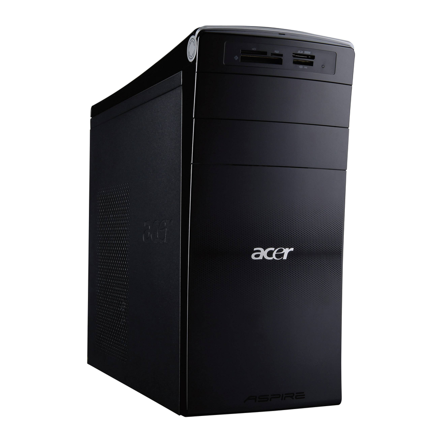
System Components This section is a virtual tour of the system’s interior and exterior components. Front Panel Component USB 2.0 ports HDD activity indicator Micro SD slot XD(XD-Picture) slot CF I/II (CompactFlash Type I/II) slot Master optical drive bay Slave optical drive or Removable HDD bay Chapter 1 Slave optical drive eject button Master optical drive eject button... -
Page 14: Rear Panel
Rear Panel Component Power connector PS2 keyboard port VGA port HDMI port USB 2.0 ports Mic-in Line-out Expansion slot (graphics card and TV tuner card and Mode card) Line-in USB 2.0 ports LAN connector System FAN PS2 mouse port Chapter 1... -
Page 15: Hardware Specifications And Configurations
LAN controller Realtek RTL8111E SATA controller Intel H67 Super IO ITE IT8772E controller Chapter 1 Specification AMI Kernel with Acer skin P01-A0 SPI Flash 32Mb SMBIOS(DMI)2.4/DMI2.0 1st priority: Hard Disk 2nd priority: CD/DVT 3rd priority: Removable Device 4th priority: LAN Description Press while the system is booting to enter BIOS Setup Utility. -
Page 16: Memory Combinations
Memory Combinations Slot Memory Slot 1 1MB,2GB,4GB Slot 2 1MB,2GB,4GB Slot 3 1MB,2GB,4GB Slot 4 1MB,2GB,4GB Maximum System Memory Supported System Memory Item Memory slot number Support Memory size per socket Support memory type Support memory interface Support memory voltage Support memory module package Support to parity check feature Support to error correction code (ECC) feature No... -
Page 17: Sata Interface
SATA Interface Item SATA controller Number of SATA channel Support mode USB Port Item Universal HCI USB Class USB Connectors Quantity Environmental Requirements Item Specification Temperature Operating +5°C ~ +35°C Non-operating -20 ~ +60°C (Storage package) Humidity Operating 15% to 80% RH Non-operating 10% to 90% RH Vibration... -
Page 18: Power Management Function(Acpi Support Function)
Power Management Function(ACPI support function) Device Standby Mode Independent power management timer for hard disk drive devices(0-15 minutes,time step=1minute). • Hard Disk drive goes into Standby mode(for ATA standard interface). • Disable V-sync to control the VESA DPMS monitor. • Resume method:device activated (keyboard for DOS, keyboard &mouse for Windows. -
Page 19: System Utilities
System Utilities CMOS Setup Utility CMOS setup is a hardware configuration program built into the system ROM, called the complementary metal- oxide semiconductor (CMOS) Setup Utility. Since most systems are already properly configured and optimized, there is no need to run this utility. You will need to run this utility under the following conditions. When changing the system configuration settings •... -
Page 20: Entering Cmos Setup
Entering CMOS setup Turn on the server and the monitor. If the server is already turned on, close all open applications, then restart the server. During POST, press Delete. If you fail to press Delete before POST is completed, you will need to restart the server. The Setup Main menu will be displayed showing the Setup’s menu bar. -
Page 21: Setup Utility Menus
Setup Utility Menus Main The Setup Main menu includes the following main setup categories. Parameter Description System BIOS Version Version number of the BIOS setup utility. Build Date Date when the BIOS setup utility was built Processor Type of CPU installed on the system. Core Frequency Core speed of the CPU installed on the system. - Page 22 Advanced Parameter Miscellaneous Advanced Chipset Configuration Integrated Peripherals PC Health Status Description Press Enter to access the Miscellaneous submenu Press Enter to access the Advanced Chipset Configuration submenu Press Enter to access the Integrated Peripherals submenu Press Enter to access the PC Health Status submenu Chapter 2...
- Page 23 Miscellaneous Parameter Description AHCI Port1/2/3/4/5 Displays the status of auto detection of the AHCI device. Clock to All DIMM/ This item allows you to enable or disable the Clock to all DIMM/PCI/PCIE. PCI/PCIE Bootup Num-lock Selects power on state for Num Lock. USB Beep Message Enables or disables BIOS to display error beeps or messages during USB device enumeration.
-
Page 24: Advanced Chipset Configuration
Advanced Chipset Configuration Intel EIST This item allows users to enable or disable the EIST (Enhanced Intel SpeedStep technology). Intel Turbo Boost This item allows users to enable or disable the Intel Turbo Boost. Intel AES-NI Enables or disables Advanced Encryption Standard New Instructions (AES-NI). -
Page 25: Integrated Peripherals
Integrated Peripherals Parameter Description Onboard SATA Controller Enables or disables the onboard SATA controller. Onboard SATA Mode Select an operating mode for the onboard SATA. Onboard USB Controller Enables or disables the onboard USB controller. Legacy USB Support Enables or disables support for legacy USB devices. USB Storage Emulation If Auto, USB device equal or less than 2GB will be emulated as Floppy and remaining as harddrive. -
Page 26: Pc Health Status
PC Health Status Parameter Description Smart Fan Enables or disables the smart system fan control function. Option Enabled Disabled Chapter 2... - Page 27 Power Parameter Description ACPI Suspend Mode Select an ACPI state. Deep Power Off Mode Select the Deep power off Mode Power On by RTC Alarm Enables or Disables to wake up the system by RTC Alarm Function Power On by PCIE Devices This system can be turned off with a software commend.
- Page 28 Security Parameter Description Supervisor Password This item indicates whether a supervisor password has been set. If the password has been installed, Installed displays. If not, Not Installed displays. User Password This item allows you to change user password. Change Supervisor You can select this option and press <Enter>...
-
Page 29: Boot Options
Boot Options 1st/2nd/3rd/4th/5th Boot Specifies the boot order from the available devices. Device EFI Device Priority Press Enter to access the EFI Device Priority submenu and specify the boot device priority sequence from available EFI devices. Hard Disk Drive Priority Press Enter to access the Hard Disk Drive Priority submenu and specify the boot device priority sequence from available hard drives. - Page 30 Exit Parameter Description Save & Exit Setup When you have completed the system configuration changes, select this option to leave the BIOS Setup Utility and reboot the computer, so the new system configuration parameters can take effect. Select Discard Changes and Exit Select this option to quit the BIOS Setup Utility without making any permanent changes to the Setup system configuration, and reboot the computer.
-
Page 31: System Disassembly And Assembly
System Disassembly and Assembly This chapter contains step-by-step procedures on how to disassemble and assembly the desktop computer for maintenance and troubleshooting. Disassembly Requirements To disassemble the computer, you need the following tools: Wrist grounding strap and conductive mat for preventing electrostatic discharge •... -
Page 32: Pre-Disassembly Procedure
Pre-disassembly Procedure Before proceeding with the disassembly procedure, perform the steps listed below: Turn off the system and all the peripherals connected to it. Unplug the power cord from the power outlets. Unplug the power cord from the system. Unplug all peripheral cables from the system. Place the system unit on a flat, stable surface. -
Page 33: Removing The Side Panel
Removing the Side Panel Remove the two screws located on the rear edge of the side panel. Slide the side panel toward the back of the chassis until the tabs on the cover disengage with the slots on the chassis. Lift the side panel away from the server and put it aside for reinstallation later. -
Page 34: Removing The Front Bezel
Removing the Front Bezel Remove the side panel. Refer to the previous section for instructions. Release the front bezel from the chassis interior. Pull the bezel away from the chassis. Chapter 3... -
Page 35: Removing The Heat Sink Fan Assembly
Removing the Heat Sink Fan Assembly WARNING:The heat sink becomes very hot when the system is on. NEVER touch the heat sink with any metal or with your hands. Disconnect the fan cable from the mainboard. Use a long-nosed screwdriver to loosen the four screws on the heat sink, in the order as shown below. Note :CPU Fan has been highlighted with the yellow rectangle as above image shows.Please detach the CPU Fan and follow local regulations for disposal. - Page 36 Lift the heat sink fan assembly away from the mainboard. Remove the heat sink fan assembly then lay it down in an upright position—with the thermal patch facing upward. Do not let the thermal patch on the heat sink fan assembly touch the work surface. Use an alcohol pad to wipe off the thermal grease from both the heat sink and the processor.
-
Page 37: Removing The Processor
Removing the Processor IMPORTANT:Before removing a processor from the mainboard, make sure to create a backup file of all important data. WARNING:The processor becomes very hot when the system is on. Allow it to cool off first before handling. Release the load lever. Lift the load lever and load plate to the fully open, upright position (1) and (2). - Page 38 Pull out the processor from the socket. IMPORTANT: If you are going to install a new processor, note the arrow on the corner to make sure the processor is properly oriented over the socket. Chapter 3...
-
Page 39: Removing The Vga Card
Removing the VGA Card Open PCI Latch. Remove the screw that secures the card to the chassis. Gently pull the card to remove it from the mainboard. Note: Circuit boards >10 cm² has been highlighted with the yellow rectangle as above image shows. Please detach the Circuit boards and follow local regulations for disposal. -
Page 40: Removing The Wireless Lan Card
Removing the Wireless Lan Card Remove the screw that secures the card to the chassis. Gently pull the card to remove it from the mainboard. Note: Circuit boards >10 cm² has been highlighted with the yellow rectangle as above image shows. Please detach the Circuit boards and follow local regulations for disposal. -
Page 41: Removing The Tv-Tuner Card
Removing the TV-Tuner Card Remove the screw that secures the card to the chassis. Gently pull the card to remove it from the mainboard. Note: Circuit boards >10 cm² has been highlighted with the yellow rectangle as above image shows. Please detach the Circuit boards and follow local regulations for disposal. -
Page 42: Removing The Pci-E Modem Card
Removing the PCI-E Modem Card Remove the screw that secures the card to the chassis. Gently pull the card to remove it from the mainboard. Note: Circuit boards >10 cm² has been highlighted with the yellow rectangle as above image shows. Please detach the Circuit boards and follow local regulations for disposal. -
Page 43: Removing The Memory Modules
Removing the Memory Modules IMPORTANT:Before removing any DIMM from the memory board, make sure to create a backup file of all important data. Press the holding clips on both sides of the DIMM slot outward to release the DIMM(1). Gently pull the DIMM upward to pull it away from the M/B(2). Note: Circuit boards >10 cm²... -
Page 44: Removing The Hard Disk Drive
Removing the Hard Disk Drive Disconnect the data and power cables from the rear of the optical drive. Disconnect the other end of the data cable from the main board. Remove the screw that secures the HDD cage to the chassis. Chapter 3... - Page 45 Lift the HDD cage up and turn it over. Remove the HDD module. Remove the four screws secure the HDD module to the HDD cage. Slide the HDD out of the cage. Chapter 3...
-
Page 46: Removing The Bracket Of Removable Hdd
Removing the Bracket of Removable HDD Disconnect the removable HDD date cable from the motherboard. Remove the three screws. Pull the bracket of removable HDD from the chassis. Chapter 3... -
Page 47: Removing The Optical Drive
Removing the Optical Drive Disconnect data and power cable from the rear of the optical drive. Disconnect the other end of the data cable from the mainboard. Remove the two screws from the optical drive. Chapter 3... - Page 48 Pull the ODD from the chassis. Chapter 3...
-
Page 49: Removing The System Fan
Removing the System Fan Remove system FAN cable from M/B. Use a knife to cut off the PE belt then disconnector the cable. Chapter 3... - Page 50 Release four screws according to the following picture. Take off the system fan from chassis. Note :System fan has been highlighted with the yellow rectangle as above image shows.Please detach the system fan and follow local regulations for disposal. Chapter 3...
-
Page 51: Removing The Daughter Board
Removing the Daughter Board Take out the cable from the cable retention clip, and disconnect the daughter board cable from the motherboard. Remove the screw that secures the chassis to the daughter board. Take out the daughter board. Chapter 3... -
Page 52: Removing The Power Supply
Removing the Power Supply Disconnect the 4-pin and 24-pin power supply cables from the mainboard. Remove the four screws that secures the power supply to the chassis. Lift the power supply module out of the chassis. Chapter 3... -
Page 53: Removing The Mainboard
Removing the Mainboard Open the cable retention clip, then take out the these cables from the cable retention clip. Disconnect the power switch cable/top audio cable/top USB cable/card reader cable from the main board. Release the the cable retention clip. Chapter 3... - Page 54 Remove the eight screws that secure the mainboard to the chassis. Note: Circuit boards >10 cm² has been highlighted with the yellow rectangle as above image shows. Please detach the Circuit boards and follow local regulations for disposal. Lift the board from the chassis. Chapter 3...
- Page 55 Punching in IO Shield then you can remove it. Remove the RTC battery. Note: RTC battery has been highlighted with the yellow circle as above image shows.Please detach the RTC battery and follow local regulations for disposal. Chapter 3...
-
Page 56: Removing The Top Cover
Removing the Top Cover Gently release the top bezel retention tabs from the chassis interior. When perform the step one, then release the top bezel retention tabs from the chassis interior. Chapter 3... - Page 57 Pull the top cover away from the chassis. Pull the power switch and LED cable from chassis hole. Chapter 3...
-
Page 58: Removing The Power Switch And Led Cable Assembly
Removing the Power Switch and LED Cable Assembly Release the locking tabs (1) and gently power switch cable out of the bracket (2). Release the locking tabs (1) and gently LED cable out of the bracket (2). Release the two locking tabs and take out the cable. Chapter 3... -
Page 59: Removing The Card Reader
Removing the Card Reader Removing the two screws from the chassis. Lift the card reader away from chassiss. then Pull the card reader cable from chassis hole. Chapter 3... -
Page 60: Removing The Top Usb And Audio I/O Assembly
Removing the Top USB and Audio I/O Assembly Removing the two screws from the chassis. Release these cables from the chassis. Lift the top USB and audio I/O assembly away from chassiss. Chapter 3... - Page 61 Removing the top USB and audio I/O board. Use screwdriver to remove the two screws. Grasp the bracket then gently Pull the USB board out of the bracket. Chapter 3...
-
Page 62: Assembly Requirements
Assembly Requirements To assemble the computer, you need the following tools: Wrist grounding strap and conductive mat for preventing electrostatic discharge • Flat-blade screwdriver • Philips screwdriver • Hex screwdriver • Plastic flat-blade screwdriver • Plastic tweezers • NOTE: The screws for the different components vary in size. During the assembly process, group the screws with the corresponding components to avoid mismatch when putting back the components. -
Page 63: Assembly Procedure
Assembly Procedure Before proceeding with the assembly procedure, perform the steps listed below: Turn off the system and all the peripherals connected to it. Unplug the power cord from the power outlets. Unplug the power cord from the system. Unplug all peripheral cables from the system. Place the system unit on a flat, stable surface. -
Page 64: Install The Processor
Install the Processor Release the load lever. Lift the load lever and load plate to the fully open,then take out the CPU cover. Put the CPU in the seat and close the load plate and load lever. NOTE: When you install the processor, note the arrow on the corner to make sure the processor is properly oriented over the socket. -
Page 65: Install The Heat Sink Fan Assembly
Install the Heat Sink Fan Assembly Put the CPU cooler on CPU. Use a long-nosed screwdriver to fix the four screws on the heat sink, in the order as shown below. Connect the cooler cable to the main board. Chapter 3... -
Page 66: Install The Memory
Install the Memory Open the holding clips on both sides of the DIMM slot outward. Press down the memory. IMPORTANT:pls refer to below installing memory rule. DIMM1 Remark:A and B show different size of memory, size:A>B DIMM2 DIMM3 DIMM4 Chapter 3... -
Page 67: Romoving The Side Panel
Removing the Side Panel Remove the four screws located on the rear edge of the side panel. Slide the side panel toward the back of the chassis until the tabs on the cover disengage with the slots on the chassis. Lift the side panel away from the server and put it aside for reinstallation later. -
Page 68: Removing The Daughter Board
Removing the Daughter Board Remove the screw that secures the chassis to the daughter board. Take out the daughter board. Chapter 3... -
Page 69: Removing The Cage Of Hard Disk Drive
Removing the Cage of Hard Disk Drive Remove the screw that secures the HDD cage to the chassis. Lift the HDD cage up and turn it over. Chapter 3... -
Page 70: Removing The Pci Cover
Removing the PCI Cover Remove the PCI cover. NOTE: Based to actual requirment to remove the PCI cover. Chapter 3... -
Page 71: Install The Power Supply
Install the Power Supply Install the power supply to chassis. Fix the four screws. Chapter 3... -
Page 72: Install The I/O Shielding
Install the I/O Shielding Install I/O shielding into chassis. Chapter 3... -
Page 73: Install The Main Board
Install the Main Board Put M/B in the chassis aligning the M/B I/O connector with I/O shielding. Fix1~ 8 pcs screws into the corresponding hole. NOTE: Make sure the I/O spring touching M/B after installing. Connect the ATX 24Pin Power cable and ATX 4Pin Power cable to main board. Chapter 3... - Page 74 Connector the Power switch/Top USB/Card Reader/Front bezel USB/Audio cable to motherboard. Put the power switch cable/top USB cable/card reader USB cable/top audio cable into the cable retention clip, then close the cable retention clip. Chapter 3...
-
Page 75: Install The Optical Drive
Install the Optica Drive Removing the front bezel, please refer to “Removing the front bezel” on page 26. Install the ODD into chassis. Fix the four screws. Chapter 3... - Page 76 Connect the power cables and data cable to the rear of the optical drive. Connect the other end of the data cable to the mainboard. Chapter 3...
-
Page 77: Install The Hard Disk Drive
Install the Hard Disk Drive Install the HDD. Install the slave HDD into the cage. Fix four screws for the slave HDD. Install the master HDD into the cage. Chapter 3... - Page 78 Fix four screws for the master HDD. Install HDD cage into chassis by the track. Fix the screw. Chapter 3...
- Page 79 Connect the data cable and power cable to the rear of the hard disk drive. Connect the other end of the data cable to the main board. Chapter 3...
-
Page 80: Install The Daughter Board
Install the Daughter Board Install the daughter board into chassis. Fix the screw. Connect the daughter board cable to the motherboard. then paste cable clip to base of chassis, and put daughter board cable into the cable clip. Chapter 3... -
Page 81: Install The System Fan
Install the System FAN Push the system fan to chassis. Fix the four screws. Connect the system fan power cable to Main board. Chapter 3... -
Page 82: Install The Pci-E Modem Card
Install the PCI-E Modem Card Open PCI Latch. Install the PCI-E modem card to motherboard “PCIE X1” slot. NOTE: You install before the card, rear USB cable througt the PCI-E modem card underside. Chapter 3... -
Page 83: Install The Tv-Tuner Card
Install the the TV-Tuner Card Install the TV-Tuner card to motherboard “PCIE X1” slot. NOTE: You install before the card, rear USB cable througt the TV-Tuner card underside. Chapter 3... -
Page 84: Install The Wireless Lan Card
Install the Wireless LAN Card Install the wireless LAN card to motherboard “PCIE X1” slot. NOTE: You install before the card, rear USB cable througt the wireless Lan card underside. Chapter 3... -
Page 85: Install The Vga Card
Install the VGA Card Install the VGA card to motherboard “PCIE X16” slot. NOTE: You install before the card, rear USB cable througt the VGA card underside. Close the PCI Latch, fix the three screws. Chapter 3... -
Page 86: Install The Front Bezel
Install the Front Bezel Connect the data cable of removable HDD to main board. Clear up these cables. then use PE belt to bundle these cables. Install the panel onto chassis and then check if it is Installed OK. Chapter 3... -
Page 87: Install The Side Panel
Install the Side Panel Install the side Panel, then fix two Screws. Chapter 3... -
Page 88: System Troubleshooting
This chapter provides instructions on how to troubleshoot system hardware problems. Hardware Diagnostic Procedure IMPORTANT:The diagnostic tests described in this chapter are only intended to test Acer products. Non- Acerproducts, prototype cards, or modified options can give false errors and invalid systemresponses. -
Page 89: System Check Procedures
Verify that components are properly seated. Verify that all cable connectors inside the system are firmly and correctly attached to their appropriate connectors. Verify that all components are Acer-qualified and supported. 10. Replace the system covers. 11. Power on the system. -
Page 90: Beep Codes
Beep Codes Beep codes are used by the BIOS to indicate a serious or fatal error to the end user. Beep codes are used when an error occurs before the system video has been initialized. Beep codes will be generated by the system board speaker, commonly referred to as the PC speaker. -
Page 91: Checkpoints
Checkpoints A checkpoint is either a byte or word value output to I/O port 80h.The BIOS outputs checkpoints throughout bootblock and Power-On Self Test (POST) to indicate the task the system is currently executing. Checkpoint sare very useful in aiding software developers or technicians in debugging problems that occur during the pre- boot process. - Page 92 Checkpoint Restore CPUID value back into register. Give control to BIOS POST (ExecutePOSTKernel). See POST Code Checkpoints section of document for more information. System is waking from ACPI S3 state. E1-E8 EC- OEM memory detection/configuration error. This range is reserved for chipset vendors & system manufacturers.
-
Page 93: Bootblock Recovery Code Checkpoints
Bootblock Recovery Code Checkpoints The Bootblock recovery code gets control when the BIOS determines that a BIOS recovery needs to occur because the user has forced the update or the BIOS checksum is corrupt. The following table describes the type of checkpoints that may occur during the Bootblock recovery portion of the BIOS. NOTE: Checkpoints may differ between different platforms based on system configuration. -
Page 94: Bios Recovery
BIOS Recovery The usage of recovery boot block: Please re-name BIOS ROM (xxxx.ROM or 2MB size ROM) file to “AMIBOOT.ROM” and burn in • BIOS ROM file to CDROM or copy BIOS ROM file to USB Thumb drive. Automatic mode: When BIOS flash crashed, using recovery CDROM/USB Thumb drive to recover BIOS. - Page 95 Select “Proceed with flash update” and Press “Enter”. Chapter 4...
- Page 96 System will start to flash update progress. Once firmware update is completed, press any key to reboot the system. Chapter 4...
-
Page 97: Jumper And Connector Information
Chapter 5 Jumper and Connector Information M/B Placement Chapter 5... - Page 98 Label CPU socket ATX_CPU System Fan SATA1~6 F_USB1 F_USB3 F_AUDIO PCIE X16 Board ID C_MOS Description CPU socket for SNB CPU Power connector Sys Fan header SATA connectors Card reader USB header Front panel USB header Front panel audio header PCIEx16 slot SPI header Board ID SeL Header...
-
Page 99: Jumper Setting
Jumper Setting The section explains how to set jumper for correct configuration of the mainboard. Setting Jumper Use the motherboard jumpers to set system configuration options. Jumpers with more numbered. When setting the jumpers, ensure that the jumper caps are Internal header pin definition Jumper/Header Name CPU_FAN (4 PIN) - Page 100 Jumper/Header Name F_USB1, F_USB2, F_USB3, F_USB4 F_AUDIO Function FRONT USB HEADER (2X5) Yellow is symbol, Red is Pin 1 of symbol. FRONT PANEL AUDIO HEADER (2X5) Yellow is symbol, Red is Pin 1 of symbol. Definition 1. VCC5 2. VCC5 3.
- Page 101 Jumper/Header Name SPDIF_OUT, SPDIF_OUT1 F_PANEL Chapter 5 Function Yellow is symbol, Red is Pin 1 of symbol. Front panel header Yellow is symbol, Red is Pin 1 of symbol. TPM Header Definition 1: VCC (5V_SYS) 2: KEY 3: A_SPDIF_OUT1 4: GND 1: HDD+ (PU 5V_S0) 2: PWRLED_PN2(PU 5V_S5)
- Page 102 Jumper/Header Name SPEAKER Function Printer Header Yellow is symbol, Red is Pin 1 of symbol. Audio internal speaker header Yellow is symbol, Red is Pin 1 of symbol. Definition 1: STRBJ 2: AFDJ 3: PRP_D0 4: PRERRJ 5:PRP_D1 6: INITJ 7: PRP_D2 8: SLINJ 9: PRP_D3...
- Page 103 USB CONNECTORS (Quad stack) "11,21,31,41" "1,2,3,4,5,6" LAN+Dual USB Connector 23,24,25,26 Chapter 5 Signal Name VCC_USB USB6N USB6P Ground USB7N USB7P Ground USB2N USB2P Ground USB3N USB3P Ground Ground Signal Name VCC_USB USBIN_R USBIP_R USB0N_R USB0P_R MD10+ MD10- MD11+ MD11- MD12+...
-
Page 104: Sata Port
27,28,29,30 Audio Back Panel Connectors G1,G2,G3,G4 SATA port Signal Name MD12- MD13+ MD113- ACTLEDP ACTLEDN 1G_LED 100_LED Signal Name LIN1_L LIN1_JD AGND LIN1_R LOUT1_L LOUT1_JD AGND LOUT1_R MIC1_L MIC1_JD AGND MIC1_R AGND AGND Signal Name SATA_TX0+_ SATA_TX0-_C SATA_RX0-_C SATA_RX0+_C Chapter 5... -
Page 105: Vga Connector
PS2 Connector(KB/MS) 8,12 13,14,15,16,1 VGA Connector 5,6,7,8,10 HDMI Connector Chapter 5 Signal Name KDATA 5V_PS2 KCLK MDATA 5V_PS2 MCLK Signal Name GREEN BLUE LOUT1_L 5V_VGA HSYNC VSYNC Signal Name HDMI_TXDP2_C HDMI_TXDN2_C HDMI_TXDP1_C HDMI_TXDN1_C HDMI_TXDP0_C HDMI_TXDN0_C HDMI_TXCP_C HDMI_TXCN_C... - Page 106 Signal Name HDMI_DDCCLK_C HDMI_DDCDATA_C 5V_HDMI_C HP_DET_C Chapter 5...
-
Page 107: Fru (Field Replaceable Unit) List
To scrap or to return the defective parts, follow the local government ordinance or regulations on • how to dispose it properly, or follow the rules set by your regional Acer office on how to return it. This document will be updated as more information about the FRU list becomes available. -
Page 108: Aspire M3970 Exploded Diagram
Aspire M3970 Exploded Diagram This section will be updated when more information becomes available. NOTE: Chapter 6... - Page 109 ODD Button Up Chapter 6 Q’TY ITEM NAME ODD Button Dn Pole ODD Door Up ODD Door Dn Deco Bezel Acer Logo Hinge ODD Door Main Bezel Front Chassis Link BKT(Option) PCI BKT(Option) ODD Cage Bottom Venting(Option) HDD Cage Side Door...
-
Page 110: Aspire M3970 Fru List
Aspire M3970 FRU List Category MB Kit MB kit aVictoria Intel H67 Realtek 8111E Acer Logo uATX W/O 1394 LF w/o USB3.0, B3 stepping Chassis Aspire 2011 M3 w/o HDD carrier Aspire 2011 M3 w/ HDD carrier Bezel Aspire 2011 M3 w/o HDD carrier... - Page 111 "HDD SEAGATE 3.5"" 7200rpm 320GB ST3320413AS(Pharaoh 6G) SATA III 16MB LF F/ W:JC45" "HDD SEAGATE 3.5"" 7200rpm 500GB ST3500413AS(Pharaoh 6G) SATA III 16MB LF F/ W:JC45 " Chapter 6 Part Number Exploded Acer P/N Diagram Item KC.26001.CI7 KC.25001.CI5 KC.24001.CI5 KC.23001.CI5 KC.21201.CI3 KC.21001.CI3 KN.1GB0B.036 KN.2GB0B.033...
- Page 112 ODD HLDS BD COMBO HH 6X CH20N Black Bezel SATA HF + Win7 ODD PLDS BD COMBO HH 6X DH-6E2S Black Bezel SATA w/ Win 7 D13M2-35 Part Number Exploded Acer P/N Diagram Item KH.01K01.016 KH.15K01.002 KH.32008.023 KH.50008.022 KH.01K08.012 KH.01K08.008 KH.01K08.013...
- Page 113 DVI-I + HDMI Hynix DFR (ATX) 89D386-321107 HD6450 sDDR3 64bits DVI-I + HDMI SAMSUNG (ATX) TV-Tuner Avermedia H753-A TV Tuner Card PCIe Hybrid ATSC, S/W Encoder, ATX bracket Chapter 6 Part Number Exploded Acer P/N Diagram Item VG.PCPT4.251 VG.PCPT4.252 VG.PCPT4.201 VG.PCPT4.202 VG.APC65.701 VG.APC65.703 VG.PCPT4.003 VG.PCPT4.005...
- Page 114 RA351, NEC μPD720200, USB 3.0 PCI-Ex1 card, 2 extermal ports, 1 PATA 4-pin power connector, 50mm height PCB, Full-height bracket + 700mm power Y-cable (1SATA to 1SATA + 1PATA) External Speaker Neosonica Speaker Acer logo /LF /0810 / 9M- 20A200-000 Power Supply Part Number Exploded...
- Page 115 Keyboard LITE-ON SK-9660B RF2.4 104KS Black Traditional Chinese Keyboard LITE-ON SK-9660B RF2.4 104KS Black Simplified Chinese Keyboard LITE-ON SK-9660B RF2.4 104KS Black US International Chapter 6 Part Number Exploded Acer P/N Diagram Item PY.30008.032 PY.30008.033 PY.30009.021 PY.3000B.016 RT.11300.021 RT.11300.022 RV.11000.025 RV.11000.007...
- Page 116 Keyboard LITE-ON SK-9660B RF2.4 105KS Black Polish Keyboard LITE-ON SK-9660B RF2.4 105KS Black Slovenian Keyboard LITE-ON SK-9660B RF2.4 105KS Black Slovak Keyboard LITE-ON SK-9660B RF2.4 104KS Black Russian Part Number Exploded Acer P/N Diagram Item KB.RF40B.046 KB.RF40B.047 KB.RF40B.048 KB.RF40B.049 KB.RF40B.050 KB.RF40B.051 KB.RF40B.052 KB.RF40B.053 KB.RF40B.054...
- Page 117 Keyboard PRIMAX KBRF36211 RF2.4 104KS Black Simplified Chinese Keyboard PRIMAX KBRF36211 RF2.4 104KS Black US International Keyboard PRIMAX KBRF36211 RF2.4 104KS Black Arabic/English Chapter 6 Part Number Exploded Acer P/N Diagram Item KB.RF40B.068 KB.RF40B.069 KB.RF40B.070 KB.RF40B.071 KB.RF40B.072 KB.RF40B.073 KB.RF40B.074 KB.RF40B.075 KB.RF40B.076...
- Page 118 Keyboard PRIMAX KBRF36211 RF2.4 105KS Black Slovenian Keyboard PRIMAX KBRF36211 RF2.4 105KS Black Slovak Keyboard PRIMAX KBRF36211 RF2.4 104KS Black Russian Keyboard PRIMAX KBRF36211 RF2.4 105KS Black Hungarian Part Number Exploded Acer P/N Diagram Item KB.RF40P.006 KB.RF40P.007 KB.RF40P.008 KB.RF40P.009 KB.RF40P.010 KB.RF40P.011 KB.RF40P.012 KB.RF40P.013 KB.RF40P.014...
- Page 119 Simplified Chinese Keyboard LITE-ON SK-9621B USB 104KS Black US International Keyboard LITE-ON SK-9621B USB 104KS Black Arabic/English Keyboard LITE-ON SK-9621B USB 104KS Black Thailand Chapter 6 Part Number Exploded Acer P/N Diagram Item KB.RF40P.028 KB.RF40P.029 KB.RF40P.030 KB.RF40P.031 KB.RF40P.032 KB.RF40P.033 KB.RF40P.034 KB.RF40P.035 KB.RF40P.036...
- Page 120 Keyboard LITE-ON SK-9621B USB 105KS Black Slovak Keyboard LITE-ON SK-9621B USB 104KS Black Russian Keyboard LITE-ON SK-9621B USB 105KS Black Hungarian Keyboard LITE-ON SK-9621B USB 104KS Black Greek Part Number Exploded Acer P/N Diagram Item KB.USB0B.336 KB.USB0B.337 KB.USB0B.338 KB.USB0B.339 KB.USB0B.340 KB.USB0B.341 KB.USB0B.342 KB.USB0B.343 KB.USB0B.344...
- Page 121 Arabic/English Keyboard PRIMAX KB36211 USB 104KS Black Thailand Keyboard PRIMAX KB36211 USB 105KS Black Spanish Keyboard PRIMAX KB36211 USB 105KS Black Portuguese Chapter 6 Part Number Exploded Acer P/N Diagram Item KB.USB0B.358 KB.USB0B.359 KB.USB0B.360 KB.USB0B.361 KB.USB0B.362 KB.USB0B.363 KB.USB0B.364 KB.USB0B.365 KB.USB0B.366 KB.USB0B.367...
- Page 122 Keyboard PRIMAX KB36211 USB 105KS Black Hungarian Keyboard PRIMAX KB36211 USB 104KS Black Greek Keyboard PRIMAX KB36211 USB 105KS Black Danish Keyboard PRIMAX KB36211 USB 104KS Black Czech Part Number Exploded Acer P/N Diagram Item KB.USB0P.009 KB.USB0P.010 KB.USB0P.011 KB.USB0P.012 KB.USB0P.013 KB.USB0P.014 KB.USB0P.015 KB.USB0P.016 KB.USB0P.017...
- Page 123 Keyboard LITE-ON SK-9611 PS/2 105KS Black Portuguese Keyboard LITE-ON SK-9611 PS/2 105KS Black Canadian French Keyboard LITE-ON SK-9611 PS/2 107KS Black Brazilian Portuguese Chapter 6 Part Number Exploded Acer P/N Diagram Item KB.USB0P.031 KB.USB0P.032 KB.USB0P.033 KB.USB0P.034 KB.USB0P.035 KB.USB0P.036 KB.USB0P.037 KB.USB0P.038 KB.USB0P.039...
- Page 124 Keyboard LITE-ON SK-9611 PS/2 105KS Black Danish Keyboard LITE-ON SK-9611 PS/2 104KS Black Czech Keyboard LITE-ON SK-9611 PS/2 105KS Black Romanian Keyboard LITE-ON SK-9611 PS/2 105KS Black Turkish Part Number Exploded Acer P/N Diagram Item KB.PS20B.125 KB.PS20B.126 KB.PS20B.127 KB.PS20B.128 KB.PS20B.129 KB.PS20B.130 KB.PS20B.131 KB.PS20B.132 KB.PS20B.133...
- Page 125 Canadian French Keyboard PRIMAX KB36111 PS/2 107KS Black Brazilian Portuguese Keyboard PRIMAX KB36111 PS/2 109KS Black Japanese Keyboard PRIMAX KB36111 PS/2 105KS Black German Chapter 6 Part Number Exploded Acer P/N Diagram Item KB.PS20B.147 KB.PS20B.148 KB.PS20B.149 KB.PS20B.150 KB.PS20B.151 KB.PS20B.152 KB.PS20B.153 KB.PS20B.154 KB.PS20B.155...
- Page 126 Keyboard PRIMAX KB36111 PS/2 105KS Black Romanian Keyboard PRIMAX KB36111 PS/2 105KS Black Turkish Keyboard PRIMAX KB36111 PS/2 105KS Black Turkish-Q Keyboard PRIMAX KB36111 PS/2 105KS Black Arabic/French Part Number Exploded Acer P/N Diagram Item KB.PS20P.085 KB.PS20P.086 KB.PS20P.087 KB.PS20P.088 KB.PS20P.089 KB.PS20P.090 KB.PS20P.091 KB.PS20P.092 KB.PS20P.093...
- Page 127 Czech/Slovak Keyboard PRIMAX KB36111 PS/2 105KS Black Swiss/FR Keyboard PRIMAX KB36111 PS/2 106KS Black Korean Keyboard PRIMAX KB36111 PS/2 105KS Black Spanish Latin Chapter 6 Part Number Exploded Acer P/N Diagram Item KB.PS20P.107 KB.PS20P.108 KB.PS20P.109 KB.PS20P.110 KB.PS20P.111 KB.PS20P.112 KB.PS20P.113 KB.PS20P.114...