
Related Manuals for Asus ROG STRIX B450-I


Summary of Contents for Asus ROG STRIX B450-I
- Page 1 ROG STRIX B450-I GAMING E14337_ROG_STRIX_B450-I_GAMING_UM.indb 1 2018-06-15 18:28:24...
- Page 2 Product warranty or service will not be extended if: (1) the product is repaired, modified or altered, unless such repair, modification of alteration is authorized in writing by ASUS; or (2) the serial number of the product is defaced or missing.
-
Page 3: Table Of Contents
Contents Safety information ....................... v About this guide ......................vi ROG STRIX B450-I GAMING specifications summary .......... viii Package contents ...................... xii Installation tools and components ................. xiii Chapter 1: Product Introduction Motherboard overview ................1-1 1.1.1 Before you proceed ..............1-1 1.1.2... - Page 4 3.6.10 USB Configuration ..............3-18 Monitor menu ................... 3-19 Boot menu ....................3-19 Tool menu ....................3-21 3.9.1 ASUS EZ Flash 3 Utility ............3-21 3.9.2 ASUS Secure Erase..............3-22 3.9.3 ASUS User Profile..............3-23 3.9.4 ASUS SPD Information ............. 3-23 3.9.5...
-
Page 5: Safety Information
Safety information Electrical safety • To prevent electrical shock hazard, disconnect the power cable from the electrical outlet before relocating the system. • When adding or removing devices to or from the system, ensure that the power cables for the devices are unplugged before the signal cables are connected. If possible, disconnect all power cables from the existing system before you add a device. -
Page 6: About This Guide
Refer to the following sources for additional information and for product and software updates. ASUS website The ASUS website (www.asus.com) provides updated information on ASUS hardware and software products. Optional documentation Your product package may include optional documentation, such as warranty flyers, that may have been added by your dealer. - Page 7 Conventions used in this guide To ensure that you perform certain tasks properly, take note of the following symbols used throughout this manual. DANGER/WARNING: Information to prevent injury to yourself when trying to complete a task. CAUTION: Information to prevent damage to the components when trying to complete a task.
-
Page 8: Rog Strix B450-I Gaming Specifications Summary
ROG STRIX B450-I GAMING specifications summary AM4 socket for AMD Ryzen™ 2nd Generation/Ryzen™ with Radeon™ Vega Graphics / Ryzen™ 1st Generation Processors Supports CPU up to 8 cores* * Due to CPU limitation, CPU cores supported varies by processor. * Refer to www.asus.com for the AMD ®... - Page 9 ROG STRIX B450-I GAMING specifications summary SupremeFX S1220A 8-Channel High Definition Audio CODEC - Supports up to 32-Bit/192kHz playback* - High quality 120 dB SNR stereo playback output and 113 dB SNR recording input - Impedance sense for front and rear headphone outputs...
- Page 10 1 x Anti-surge LAN (RJ45) port Back I/O Ports 1 x ASUS Wi-Fi module (Wi-Fi 802.11 a/b/g/n/ac and Bluetooth v4.2) 3 x LED-illuminated audio jacks* * Use a chassis with HD audio module in the front panel to support an 8-channel audio output.
- Page 11 ACPI 6.0, Multi-language BIOS, ASUS EZ Flash 3, CrashFree BIOS 3, F11 EZ Tuning Wizard, F6 Qfan Control, F3 My Favorites, BIOS Last Modified log, F12 PrintScreen and ASUS DRAM SPD (Serial Presence Detect) memory information, Secure Erase, User Profile, F4 AURA ON/OFF, F9 Search...
-
Page 12: Package Contents
1 x ROG STRIX B450-I GAMING motherboard 2 x SATA 6 Gb/s cables Cables 1 x Addressable LED extension cable 1 x Panel Cable 1 x ASUS 2x2 dual band Wi-Fi moving antennas (Wi-Fi 802.11a/b/g/n/ac compliant) 1 x I/O shield 1 x ROG Strix sticker Accessories 1 x M.2 mounting kit... -
Page 13: Installation Tools And Components
Installation tools and components 1 Bag of screws Phillips (cross) screwdriver PC chassis Power supply unit AMD AM4 CPU AMD AM4 compatible CPU Fan DDR4 DIMM SATA hard disk drive SATA optical disc drive (optional) Graphics card (optional) The tools and components in the table above are not included in the motherboard package. xiii E14337_ROG_STRIX_B450-I_GAMING_UM.indb 13 2018-06-15 18:28:25... - Page 14 E14337_ROG_STRIX_B450-I_GAMING_UM.indb 14 2018-06-15 18:28:25...
-
Page 15: Chapter 1: Product Introduction
Chapter 1: Product Introduction Product Introduction Motherboard overview 1.1.1 Before you proceed Take note of the following precautions before you install motherboard components or change any motherboard settings. • Unplug the power cord from the wall socket before touching any component. • Before handling components, use a grounded wrist strap or touch a safely grounded object or a metal object, such as the power supply case, to avoid damaging them due to static electricity. • Hold components by the edges to avoid touching the ICs on them. • Whenever you uninstall any component, place it on a grounded antistatic pad or in the bag that came with the component. • Before you install or remove any component, ensure that the ATX power supply is switched off or the power cord is detached from the power supply. Failure to do so may cause severe damage to the motherboard, peripherals, or components. ROG STRIX B450-I GAMING E14337_ROG_STRIX_B450-I_GAMING_UM.indb 1 2018-06-15 18:28:26... -
Page 16: Motherboard Layout
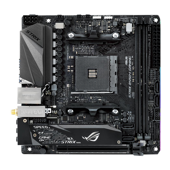
1.1.2 Motherboard layout AMD B450 Refer to 1.1.8 Internal connectors and 2.2.1 Rear I/O connection for more information about rear panel connectors and internal connectors. Chapter 1: Product Introduction E14337_ROG_STRIX_B450-I_GAMING_UM.indb 2 2018-06-15 18:28:26... - Page 17 1-17 CHA_FAN) AM4 CPU socket Addressable RGB header (4-1 pin ADD_HEADER1) 1-14 AURA RGB header (4-pin RGB_HEADER) 1-15 DDR4 DIMM slots System panel connectors (10-1 pin F_PANEL; 4-pin SPEAKER) 1-16 Serial ATA 6.0 Gb/s connectors (7-pin SATA6G_1-4) 1-11 ® Thermal sensor connector (2-pin T_SENSOR) 1-17 10. USB 2.0 connector (10-1 pin USB12) 1-12 11. USB 3.1 Gen 1 connector (20-1 pin U31G1_12) 1-13 12. Clear RTC RAM jumper (2-pin CLRTC) 13. M.2 sockets (M.2_1; M.2_2) 1-18 14. Front panel audio connector (10-1 pin AAFP) 1-13 15. RGB LED 1-10 ROG STRIX B450-I GAMING E14337_ROG_STRIX_B450-I_GAMING_UM.indb 3 2018-06-15 18:28:26...
-
Page 18: Central Processing Unit (Cpu)
1.1.3 Central Processing Unit (CPU) The motherboard comes with an AM4 socket designed for AMD Ryzen™ 2nd Generation / Ryzen™ 1st Generation / Ryzen™ with Radeon™ Vega Graphics Processors. ROG STRIX B450-I GAMING CPU AM4 The AM4 socket has a different pinout design. Ensure that you use a CPU designed for the AM4 socket. The CPU fits in only one correct orientation. DO NOT force the CPU into the socket to prevent bending the connectors on the socket and damaging the CPU! Ensure that all power cables are unplugged before installing the CPU. Chapter 1: Product Introduction E14337_ROG_STRIX_B450-I_GAMING_UM.indb 4 2018-06-15 18:28:26... -
Page 19: System Memory
1.1.4 System memory The motherboard comes with two (2) Double Data Rate 4 (DDR4) Dual Inline Memory Modules (DIMM) slots. A DDR4 module is notched differently from a DDR, DDR2, or DDR3 module. DO NOT install a DDR, DDR2, or DDR3 memory module to the DDR4 slot. ROG STRIX B450-I GAMING 288-pin DDR4 DIMM socket Recommended memory configurations ROG STRIX B450-I GAMING E14337_ROG_STRIX_B450-I_GAMING_UM.indb 5 2018-06-15 18:28:26... - Page 20 Memory configurations You may install 2 GB, 4 GB, 8 GB, and 16 GB unbuffered and non-ECC DDR4 DIMMs into the DIMM sockets. • The default memory operation frequency is dependent on its Serial Presence Detect (SPD), which is the standard way of accessing information from a memory module. Under the default state, some memory modules for overclocking may operate at a lower frequency than the vendor-marked value. • For system stability, use a more efficient memory cooling system to support a full memory load (2 DIMMs) or overclocking condition. • Always install the DIMMS with the same CAS Latency. For an optimum compatibility, we recommend that you install memory modules of the same version or data code (D/C) from the same vendor. Check with the vendor to get the correct memory modules. • Visit the ASUS website for the latest QVL. You may install varying memory sizes in Channel A and Channel B. The system maps the total size of the lower-sized channel for the dual-channel configuration. Any excess memory from the higher-sized channel is then mapped for single-channel operation. Chapter 1: Product Introduction E14337_ROG_STRIX_B450-I_GAMING_UM.indb 6 2018-06-15 18:28:27...
-
Page 21: Expansion Slots
PCIe Operating mode PCIe x16 M.2_1 M.2_1 M.2_2 (SATA mode) (PCIe mode) (PCIe mode) Support AMD Ryzen™ 2nd Generation / Ryzen™ 1st Generation Support Processors AMD Ryzen™ with Support Radeon™ Vega Support Graphics Processor ROG STRIX B450-I GAMING E14337_ROG_STRIX_B450-I_GAMING_UM.indb 7 2018-06-15 18:28:27... -
Page 22: Jumper
1.1.6 Jumper Clear RTC RAM (2-pin CLRTC) This jumper allows you to clear the Real Time Clock (RTC) RAM in CMOS. You can clear the CMOS memory of date, time, and system setup parameters by erasing the CMOS RTC RAM data. The onboard button cell battery powers the RAM data in CMOS, which include system setup information such as system passwords. To erase the RTC RAM: Turn OFF the computer and unplug the power cord. Use a metal object such as a screwdriver to short the two pins. Plug the power cord and turn ON the computer. Hold down the <Del> key during the boot process and enter BIOS setup to re- enter data. Except when clearing the RTC RAM, never place a metal object on the CLRTC jumper. Placing a metal object will cause system boot failure! If the steps above do not help, remove the onboard battery and place a metal object again to clear the CMOS RTC RAM data. After the CMOS clearance, reinstall the battery. ROG STRIX B450-I GAMING Clear RTC RAM jumper Chapter 1: Product Introduction E14337_ROG_STRIX_B450-I_GAMING_UM.indb 8 2018-06-15 18:28:27... -
Page 23: Onboard Leds
1.1.7 Onboard LEDs Standby Power LED (SB_PWR) The motherboard comes with a standby power LED. The LED lights up to indicate that the system is ON, in sleep mode, or in soft-off mode. This is a reminder that you should shut down the system and unplug the power cable before removing or plugging in any motherboard component. The illustration below shows the location of the onboard LED ROG STRIX B450-I GAMING Standby power LED Q LEDs (CPU, DRAM, VGA, BOOT) Q LEDs check key components (CPU, DRAM, VGA card, and booting devices) in sequence during motherboard booting process. If an error is found, the corresponding LED remains lit until the problem is solved. This user-friendly design provides an intuitive way to locate the root problem within seconds. ROG STRIX B450-I GAMING CPU/ DRAM/ BOOT_DEVICE/ VGA LED The order which the LEDs light up may vary per CPU. The Q LEDs provide the most probable cause of an error code as a starting point for troubleshooting. The actual cause may vary from case to case. - Page 24 RGB LED The RGB LED lighting control provides several lighting schemes, which allows you to customize your favorite LED effect. You can set your favorite LED effect to cast a stunning multi-color glow across your build, change shades to indicate CPU temperature, pulsate in time to the beat of your music, or set your favorite color for each pair of LEDs. ROG STRIX B450-I GAMING RGB LED Lighting Chapter 1: Product Introduction 1-10 E14337_ROG_STRIX_B450-I_GAMING_UM.indb 10 2018-06-15 18:28:27...
-
Page 25: Internal Connectors
Internal connectors Serial ATA 6.0 Gb/s connectors (7-pin SATA6G_1-4) ® These connectors connect to Serial ATA 6.0 Gb/s hard disk drives via Serial ATA 6.0 Gb/s signal cables. If you installed Serial ATA hard disk drives, you can create a RAID 0, 1, and 10 configuration through the onboard AMD B450 chipset. ® ROG STRIX B450-I GAMING AMD Serial ATA 6 Gb/s connectors • These connectors are set to [AHCI] by default. If you intend to create a Serial ATA RAID set using these connectors, set the SATA Mode Selection item in the BIOS to [RAID]. • Before creating a RAID set, refer to the RAID Configuration Guide. You can download the RAID Configuration Guide from the ASUS website. ROG STRIX B450-I GAMING 1-11 E14337_ROG_STRIX_B450-I_GAMING_UM.indb 11... - Page 26 ATX power connectors (24-pin EATXPWR; 8-pin EATX12V) These connectors are for ATX power supply plugs. The power supply plugs are designed to fit these connectors in only one orientation. Find the proper orientation and push down firmly until the connectors completely fit. ROG STRIX B450-I GAMING ATX power connectors • For a fully configured system, we recommend that you use a power supply unit (PSU) that complies with ATX 12 V Specification 2.0 (or later version) and provides a minimum power of 350 W. • Do not forget to connect the 8-pin EATX12 V power plug. Otherwise, the system will not boot. • We recommend that you use a PSU with a higher power output when configuring a system with more power-consuming devices. The system may become unstable or may not boot up if the power is inadequate. USB 2.0 connector (10-1 pin USB12) This connector is for a USB 2.0 port. Connect the USB module cable to this connector, then install the module to a slot opening at the back of the system chassis. This USB connector complies with USB 2.0 specification that supports up to 480 Mb/s connection speed. ROG STRIX B450-I GAMING USB 2.0 connector Never connect a 1394 cable to the USB connectors. Doing so will damage the...
- Page 27 USB 3.1 Gen 1 connector (20-1 pin U31G1_12) This connector allows you to connect a USB 3.1 Gen 1 module for additional USB 3.1 Gen 1 front or rear panel ports. With an installed USB 3.1 Gen 1 module, you can enjoy all the benefits of USB 3.1 Gen 1 including faster data transfer speeds of up to 5 Gb/s, faster charging time for USB-chargeable devices, optimized power efficiency, and backward compatibility with USB 2.0. ROG STRIX B450-I GAMING USB 3.1 Gen 1 connector The USB 3.1 Gen 1 module is purchased separately. The plugged USB 3.1 gen 1 device may run on xHCI or EHCI mode depending on the operating system’s setting. Front panel audio connector (10-1 pin AAFP) This connector is for a chassis-mounted front panel audio I/O module that supports HD Audio standard. Connect one end of the front panel audio I/O module cable to this connector. ROG STRIX B450-I GAMING Front panel audio connector We recommend that you connect a high-definition front panel audio module to this connector to avail of the motherboard’s high-definition audio capability.
- Page 28 Addressable RGB header (4-1 pin ADD_HEADER1) This connector is for individually addressable RGB WS2812B LED strips with embedded WS2811LED driver ICs. ROG STRIX B450-I GAMING ADD header The addressable RGB header supports WS2812B addressable RGB LED strips (5V/Data/ Ground), with a maximum power rating of 3A (5V) and a maximum of 60 LEDs. Before you install or remove any component, ensure that the ATX power supply is switched off or the power cord is detached from the power supply. Failure to do so may cause severe damage to the motherboard, peripherals, or components. • Actual lighting and color will vary with LED strip. • If your LED strip does not light up, check if the addressable RGB LED strip is connected in the correct orientation, and the 5V connector is aligned with the 5V header on the motherboard. • The addressable RGB LED strip will only light up under the operating system. • The addressable RGB LED strip is purchased separately. Chapter 1: Product Introduction 1-14 E14337_ROG_STRIX_B450-I_GAMING_UM.indb 14 2018-06-15 18:28:28...
- Page 29 AURA RGB header (4-pin RGB_HEADER) This connector is for RGB LED strips. ROG STRIX B450-I GAMING RGB_HEADER connector The RGB header supports 5050 RGB multi-color LED strips (12V/G/R/B), with a maximum power rating of 3A (12V), and no longer than 3 m. Before you install or remove any component, ensure that the ATX power supply is switched off or the power cord is detached from the power supply. Failure to do so may cause severe damage to the motherboard, peripherals, or components. • Actual lighting and color will vary with LED strip. • If your LED strip does not light up, check if the RGB LED extension cable and the RGB LED strip is connected in the correct orientation, and the 12V connector is aligned with the 12V header on the motherboard. • The LED strip will only light up when the system is operating. • The LED strip is purchased separately. ROG STRIX B450-I GAMING 1-15 E14337_ROG_STRIX_B450-I_GAMING_UM.indb 15 2018-06-15 18:28:28...
- Page 30 System panel connectors (10-1 pin F_PANEL; 4-pin SPEAKER) These connectors supports several chassis-mounted functions. ROG STRIX B450-I GAMING SPEAKER & F_PANEL connectors • System power LED (2-pin PLED) This 2-pin connector is for the system power LED. Connect the chassis power LED cable to this connector. The system power LED lights up when you turn on the system power, and blinks when the system is in sleep mode. • Hard disk drive activity LED (2-pin HDD_LED) This 2-pin connector is for the HDD Activity LED. Connect the HDD Activity LED cable to this connector. The HDD LED lights up or flashes when data is read from or written to the HDD. • System warning speaker (4-pin SPEAKER) This 4-pin connector is for the chassis-mounted system warning speaker. The speaker allows you to hear system beeps and warnings. • ATX power button/soft-off button (2-pin PWRBTN) This connector is for the system power button. Pressing the power button turns the system on or puts the system in sleep or soft-off mode depending on the BIOS settings. Pressing the power button for more than four seconds while the system is ON turns the system OFF. • Reset button (2-pin RESET) This 2-pin connector is for the chassis-mounted reset button for system reboot without turning off the system power.
- Page 31 Fan and pump connectors (4-pin CPU_FAN; 4-pin AIO_PUMP; 4-pin CHA_FAN) Connect the fan cables to the fan connectors on the motherboard, ensuring that the black wire of each cable matches the ground pin of the connector. ROG STRIX B450-I GAMING Fan connectors • DO NOT forget to connect the fan cables to the fan connectors. Insufficient air flow inside the system may damage the motherboard components. These are not jumpers! Do not place jumper caps on the fan connectors! • Ensure to fully insert the 4-pin CPU fan cable to the CPU fan connector. • The CPU_FAN connector supports the CPU fan of maximum (24 W) fan power. • Connect the pump cable from the all-in-one cooler (AIO cooler) to the AIO_PUMP header, and connect the fan cables to the CPU_FAN and CHA_FAN headers. Thermal sensor connector (2-pin T_SENSOR) This connector is for the thermistor cable that allows you to monitor the temperature of your motherboard’s critical components and connected devices. ROG STRIX B450-I GAMING T_SENSOR connector...
- Page 32 11. M.2 sockets (M.2_1; M.2_2) These sockets allow you to install M.2 SSD modules. ROG STRIX B450-I GAMING M.2 socket • For AMD Ryzen™ 2nd Generation/Ryzen™ 1st Generation Processors: - M .2_1 supports PCIE 3.0 x4 and SATA mode M Key design and type 2242 / 2260 / 2280 storage devices. - M .2_2 supports PCIE 3.0 x4 M Key design and type 2242 / 2260 / 2280 storage devices*. • For AMD Ryzen™ with Radeon™ Vega Graphics Processors** - M .2_1 supports PCIE 3.0 x4 and SATA mode M Key design and type 2242 / 2260 / 2280 storage devices. * M .2_2 socket shares bandwidth with PCIE x16. When M.2_2 slot runs in PCIE mode, the PCIE x16 slot will run at x8 mode. ** T he M.2_2 socket is not supported for these CPU •...
- Page 33 To install a 2242 M.2 SSD module to M.2_2 socket: Align the bigger hole on the mounting kit with the 2260 standoff and secure it with a screw. Install the 2242 M.2 SSD module to the M.2_2 socket. Secure the M.2 SSD module to the M.2_2 socket with a screw. • For a 2242 storage device, use the bundled 2242 mounting kit. • Before installing a 2242 M.2 SSD module, ensure that the mounting kit is properly installed with the bigger screw hole on the 2260 standoff. ROG STRIX B450-I GAMING 1-19 E14337_ROG_STRIX_B450-I_GAMING_UM.indb 19 2018-06-15 18:28:29...
- Page 34 Chapter 1: Product Introduction 1-20 E14337_ROG_STRIX_B450-I_GAMING_UM.indb 20 2018-06-15 18:28:29...
-
Page 35: Chapter 2: Basic Installation
AM4 socket. The CPU fits in only one correct orientation. DO NOT force the CPU into the socket to prevent bending the connectors on the socket and damaging the CPU! ROG STRIX B450-I GAMING E14337_ROG_STRIX_B450-I_GAMING_UM.indb 1 2018-06-15 18:28:32... -
Page 36: Cooling System Installation
2.1.2 Cooling system installation Apply the Thermal Interface Material to the CPU cooling system and CPU before you install the cooling system, if necessary. CPU heatsink and fan assembly Type 1 Chapter 2: Basic Installation E14337_ROG_STRIX_B450-I_GAMING_UM.indb 2 2018-06-15 18:28:33... - Page 37 CPU heatsink and fan assembly Type 2 When using this type of CPU fan, remove the screws and the retention module only. Do not remove the plate on the bottom. ROG STRIX B450-I GAMING E14337_ROG_STRIX_B450-I_GAMING_UM.indb 3 2018-06-15 18:28:34...
- Page 38 To install an AIO cooler AIO_PUMP CPU_FAN CHA_FAN Chapter 2: Basic Installation E14337_ROG_STRIX_B450-I_GAMING_UM.indb 4 2018-06-15 18:28:34...
-
Page 39: Motherboard Installation
Motherboard installation Install the I/O Shield to the chassis rear I/O panel. Place the motherboard into the chassis, ensuring that its rear I/O ports are aligned to the chassis’ rear I/O panel. ROG STRIX B450-I GAMING E14337_ROG_STRIX_B450-I_GAMING_UM.indb 5 2018-06-15 18:28:34... - Page 40 Place four (4) screws into the holes indicated by circles to secure the motherboard to the chassis. DO NOT over tighten the screws! Doing so can damage the motherboard. Chapter 2: Basic Installation E14337_ROG_STRIX_B450-I_GAMING_UM.indb 6 2018-06-15 18:28:35...
-
Page 41: Dimm Installation
2.1.4 DIMM installation To remove a DIMM ROG STRIX B450-I GAMING E14337_ROG_STRIX_B450-I_GAMING_UM.indb 7 2018-06-15 18:28:35... -
Page 42: Atx Power Connection
2.1.5 ATX power connection Ensure to connect the 8-pin power plug. 2.1.6 SATA device connection Chapter 2: Basic Installation E14337_ROG_STRIX_B450-I_GAMING_UM.indb 8 2018-06-15 18:28:35... -
Page 43: Front I/O Connector
Front I/O connector To install the front panel connector To install front panel audio connector AAFP To install USB 3.1 Gen 1 connector To install USB 2.0 connector USB 3.1 Gen 1 USB 2.0 ROG STRIX B450-I GAMING E14337_ROG_STRIX_B450-I_GAMING_UM.indb 9 2018-06-15 18:28:35... -
Page 44: Expansion Card Installation
2.1.8 Expansion card installation To install PCIe x16 cards 2-10 Chapter 2: Basic Installation E14337_ROG_STRIX_B450-I_GAMING_UM.indb 10 2018-06-15 18:28:36... -
Page 45: Installation
2.1.9 M.2 installation M.2_1 Socket (Top side) ROG STRIX B450-I GAMING 2-11 E14337_ROG_STRIX_B450-I_GAMING_UM.indb 11 2018-06-15 18:28:36... - Page 46 M.2_2 Socket (Bottom side) Supported M.2 type varies per motherboard. 2-12 Chapter 2: Basic Installation E14337_ROG_STRIX_B450-I_GAMING_UM.indb 12 2018-06-15 18:28:36...
-
Page 47: Wi-Fi Antenna Installation
2.1.10 Wi-Fi antenna installation Installing the ASUS 2x2 dual band W-Fi antennas Connect the bundled ASUS 2x2 dual band Wi-Fi antennas to the Wi-Fi ports at the back of the chassis. • Ensure that the ASUS 2x2 dual band Wi-Fi antennas are securely installed to the Wi-Fi ports. -
Page 48: Motherboard Rear And Audio Connections
Motherboard rear and audio connections 2.2.1 Rear I/O connection Rear panel connectors USB 3.1 Gen 1 ports 3, 4 USB 3.1 Gen 1 ports 5, 6 LAN (RJ-45) port* HDMI port USB 3.1 Gen 2 ports 1, 2 (Type-A) Wi-Fi 802.11 a/b/g/n/ac, Bluetooth V4.2 Color-coded LED Audio jacks** * and ** : Refer to the tables below for LAN port LEDs, and audio port definitions. -
Page 49: Audio I/O Connections
(Rear panel) Pink Mic In Mic In Bass/Center Bass/Center (Rear panel) Lime – – – Side Speaker Out (Front panel) 2.2.2 Audio I/O connections Audio I/O ports Connect to Headphone and Mic ROG STRIX B450-I GAMING 2-15 E14337_ROG_STRIX_B450-I_GAMING_UM.indb 15 2018-06-15 18:28:36... - Page 50 Connect to Stereo Speakers Connect to 2-channel Speakers Connect to 4-channel Speakers 2-16 Chapter 2: Basic Installation E14337_ROG_STRIX_B450-I_GAMING_UM.indb 16 2018-06-15 18:28:37...
- Page 51 Connect to 5.1-channel Speakers Connect to 7.1-channel Speakers ROG STRIX B450-I GAMING 2-17 E14337_ROG_STRIX_B450-I_GAMING_UM.indb 17 2018-06-15 18:28:37...
-
Page 52: Starting Up For The First Time
Starting up for the first time After making all the connections, replace the system case cover. Ensure that all switches are off. Connect the power cord to the power connector at the back of the system chassis. Connect the power cord to a power outlet that is equipped with a surge protector. Turn on the devices in the following order: Monitor External storage devices (starting with the last device on the chain) -
Page 53: Chapter 3: Bios Setup
BIOS Setup Knowing BIOS The new ASUS UEFI BIOS is a Unified Extensible Interface that complies with UEFI architecture, offering a user-friendly interface that goes beyond the traditional keyboard- only BIOS controls to enable a more flexible and convenient mouse input. You can easily navigate the new UEFI BIOS with the same smoothness as your operating system. -
Page 54: Bios Setup Program
RTC RAM via the Clear CMOS jumper. • The BIOS setup program does not support the Bluetooth devices. Please visit ASUS website for the detailed BIOS content manual. BIOS menu screen The BIOS Setup program can be used under two modes: EZ Mode and Advanced Mode. -
Page 55: Advanced Mode
Qfan Control(F6) EZ Tuning Wizard(F11) AURA ON/OFF(F4) Sub-menu items General help Go back to EZ Mode Hot Keys Last modified settings Search on the FAQ Displays a quick overview of the system status ROG STRIX B450-I GAMING E14337_ROG_STRIX_B450-I_GAMING_UM.indb 3 2018-06-15 18:28:37... - Page 56 Menu bar The menu bar on top of the screen has the following main items: For saving the frequently-used system settings and configuration. My Favorites For changing the basic system configuration Main Ai Tweaker For changing the overclocking settings For changing the advanced system settings Advanced For displaying the system temperature, power status, and changing Monitor...
- Page 57 Move your mouse over this button to show a QR code, scan this QR code on your mobile device to connect to the BIOS FAQ web page of the ASUS support website. You can also scan the following QR code:...
-
Page 58: Ez Mode
3.2.2 EZ Mode The EZ Mode provides you an overview of the basic system information, and allows you to select the display language, system performance, mode and boot device priority. To access the Advanced Mode, select Advanced Mode or press the <F7> hotkey for the advanced BIOS settings. -
Page 59: Q-Fan Control
Select a profile to Click to apply the fan setting apply to your fans Click to go back to main menu Click to undo the changes Select to manually configure your fans ROG STRIX B450-I GAMING E14337_ROG_STRIX_B450-I_GAMING_UM.indb 7 2018-06-15 18:28:38... - Page 60 Configuring fans manually Select Manual from the list of profiles to manually configure your fans’ operating speed. Speed points Select to manually configure your fans To configure your fans: Select the fan that you want to configure and to view its current status. Click and drag the speed points to adjust the fans’...
-
Page 61: Ez Tuning Wizard
Press <F11> on your keyboard or click from the BIOS screen to open EZ Tuning Wizard screen. Click OC then click Next. Select a PC scenario Daily Computing or Gaming/Media Editing, then click Next. ROG STRIX B450-I GAMING E14337_ROG_STRIX_B450-I_GAMING_UM.indb 9 2018-06-15 18:28:38... - Page 62 Select a Main Cooling System BOX cooler, Tower cooler, Water cooler, or I’m not sure, then click Next. After selecting the Main Cooling System, click Next then click Yes to start the OC Tuning. Chapter 3: BIOS Setup 3-10 E14337_ROG_STRIX_B450-I_GAMING_UM.indb 10 2018-06-15 18:28:38...
-
Page 63: My Favorites
My Favorites is your personal space where you can easily save and access your favorite BIOS items. My Favorites comes with several performance, power saving, and fast boot related items by default. You can personalize this screen by adding or removing items. ROG STRIX B450-I GAMING 3-11 E14337_ROG_STRIX_B450-I_GAMING_UM.indb 11 2018-06-15 18:28:38... - Page 64 Adding items to My Favorites To add BIOS items: Press <F3> on your keyboard or click from the BIOS screen to open Setup Tree Map screen. On the Setup Tree Map screen, select the BIOS items that you want to save in My Favorites screen.
-
Page 65: Main Menu
This item allows you to set the BCLK frequency to enhance the system performance. Use the <+> or <-> to adjust the value. We recommend you to set the value based on the CPU specification, as high BCLK frequencies may damage the CPU permanently. ROG STRIX B450-I GAMING 3-13 E14337_ROG_STRIX_B450-I_GAMING_UM.indb 13 2018-06-15 18:28:38... -
Page 66: Advanced Menu
CPU Core Ratio This item allows you to set a custom CPU core ratio. The CPU core ratio is calculated with the formula: 2 * FID / DID. Configuration options: [Auto] [Manual] The following items appear only when you set the Custom CPU Core Ratio to [Manual]. This item allows you to set the core frequency multiplier. -
Page 67: Cpu Configuration
SATA Port items show Not Present if no SATA device is installed to the corresponding SATA port. SATA Port Enable This item allows you to enable or disable the SATA Device. Configuration options: [Disabled] [Enabled] ROG STRIX B450-I GAMING 3-15 E14337_ROG_STRIX_B450-I_GAMING_UM.indb 15 2018-06-15 18:28:39... -
Page 68: Onboard Devices Configuration
SATA Mode This item allows you to set the SATA configuration. [AHCI] Set to [AHCI] when you want the SATA hard disk drives to use the AHCI (Advanced Host Controller Interface). The AHCI allows the onboard storage driver to enable advanced Serial ATA features that increases storage performance on random workloads by allowing the drive to internally optimize the order of commands. -
Page 69: Apm Configuration
This item allows you to switch off some power at S4+S5 or S5 to get the system ready for ErP requirement. When set to [Enabled], all other PME options are switched off. Configuration options: [Disabled] [Enable(S4+S5)] [Enable(S5)] ROG STRIX B450-I GAMING 3-17 E14337_ROG_STRIX_B450-I_GAMING_UM.indb 17... -
Page 70: Network Stack Configuration
Restore On AC Power Loss This item allows your system to go to ON state, OFF state, or both states after an AC power loss. When setting your system to [Last State], it goes to the previous state before the AC power loss. -
Page 71: Monitor Menu
For better compatibility, enable the CSM to fully support the non-UEFI driver add-on devices or the Windows UEFI mode. ® [Disabled] Disable the CSM to fully support the non-UEFI driver add-on devices or the Windows UEFI mode. ® ROG STRIX B450-I GAMING 3-19 E14337_ROG_STRIX_B450-I_GAMING_UM.indb 19 2018-06-15 18:28:39... - Page 72 To access Windows® OS in Safe Mode, press <F8> after POST (Windows® 8 not supported). • To select the boot device during system startup, press <F8> when the ASUS Logo appears. Boot Override These items displays the available devices. The number of device items that appears on the screen depends on the number of devices installed in the system.
-
Page 73: Tool Menu
3.9.1 ASUS EZ Flash 3 Utility This item allows you to run ASUS EZ Flash 3. When you press <Enter>, a confirmation message appears. Use the left/right arrow key to select between [Yes] or [No], then press <Enter> to confirm your choice. -
Page 74: Asus Secure Erase
To launch ASUS Secure Erase, click Tool > ASUS Secure Erase on the Advanced mode menu. Check the ASUS support site for a full list of SSDs tested with ASUS Secure Erase. The drive may become unstable if you run ASUS Secure Erase on an incompatible SSD. -
Page 75: Asus User Profile
This item displays the information and recommended configuration for the PCIE slots that the graphics card is installed in your system. This feature is only supported on selected ASUS graphics cards. Bus Interface This item allows you to select the bus interface. -
Page 76: Exit Menu
3.10 Exit menu The Exit menu items allow you to load the optimal default values for the BIOS items, and save or discard your changes to the BIOS items. You can access the EZ Mode from the Exit menu. Load Optimized Defaults This option allows you to load the default values for each of the parameters on the Setup menus. -
Page 77: Updating Bios
® ASUS EZ Flash 3: Updates the BIOS using a USB flash drive. ASUS CrashFree BIOS 3: Restores the BIOS using the motherboard support DVD or a USB flash drive when the BIOS file fails or gets corrupted. 3.11.1... -
Page 78: Asus Ez Flash 3
3.11.2 ASUS EZ Flash 3 ASUS EZ Flash 3 allows you to download and update to the latest BIOS through the Internet without having to use a bootable floppy disk or an OS-based utility. Updating through the Internet varies per region and Internet conditions. Check your local Internet connection before updating through the Internet. - Page 79 To update the BIOS by Internet: Enter the Advanced Mode of the BIOS setup program. Go to the Tool menu to select ASUS EZ Flash Utility and press <Enter>. Select via Internet. Press the Left/Right arrow keys to select an Internet connection method, and then press <Enter>.
-
Page 80: Asus Crashfree Bios 3
The BIOS file in the motherboard support DVD may be older than the BIOS file published on the ASUS official website. If you want to use the newer BIOS file, download the file at https://www.asus.com/support/ and save it to a USB flash drive. -
Page 81: Chapter 4: Raid Support
The motherboard comes with the RaidXpert2 Configuration Utility that supports Volume, RAIDABLE, RAID 0, RAID 1, and RAID 10 (depends on system licensing) configurations. For more information on configuring your RAID sets, please refer to the RAID Configuration Guide which you can find at https://www.asus.com/support. 4.1.1 RAID definitions Volume provides the ability to link-together storage from one or several disks, regardless of the size of the space on those disks. - Page 82 Chapter 4: RAID Support E14337_ROG_STRIX_B450-I_GAMING_UM.indb 2 2018-06-15 18:28:40...
-
Page 83: Appendix
The use of shielded cables for connection of the monitor to the graphics card is required to assure compliance with FCC regulations. Changes or modifications to this unit not expressly approved by the party responsible for compliance could void the user’s authority to operate this equipment. ASUS ROG STRIX B450-I GAMING E14337_ROG_STRIX_B450-I_GAMING_UM.indb 1 2018-06-15 18:28:40... - Page 84 Compliance Statement of Innovation, Science and Economic Development Canada (ISED) This device complies with Innovation, Science and Economic Development Canada licence exempt RSS standard(s). Operation is subject to the following two conditions: (1) this device may not cause interference, and (2) this device must accept any interference, including interference that may cause undesired operation of the device.
- Page 85 ASUS Recycling/Takeback Services ASUS recycling and takeback programs come from our commitment to the highest standards for protecting our environment. We believe in providing solutions for you to be able to responsibly recycle our products, batteries, other components as well as the packaging materials.
- Page 86 FCC Bluetooth Wireless Compliance The antenna used with this transmitter must not be co-located or operated in conjunction with any other antenna or transmitter subject to the conditions of the FCC Grant. Bluetooth Industry Canada Statement This Class B device meets all requirements of the Canadian interference-causing equipment regulations.
- Page 87 Unless required by applicable law or agreed to in writing, software distributed under the License is distributed on an “AS IS” BASIS, WITHOUT WARRANTIES OR CONDITIONS OF ANY KIND, either express or implied. See the License for the specific language governing permissions and limitations under the License. ASUS ROG STRIX B450-I GAMING E14337_ROG_STRIX_B450-I_GAMING_UM.indb 5 2018-06-15 18:28:40...
- Page 88 ASUSTek Computer Inc. ilmoittaa täten, että tämä laite on direktiivin 2014/53/ zahtevami in drugimi relevantnimii določili Direktive 2014/53/EU. Polno EU olennaisten vaatimusten ja muiden asiaankuuluvien lisäysten mukainen. besedilo izjave EU o skladnosti je na voljo na https://www.asus.com/support/ Koko EY:n vaatimustenmukaisuusvakuutuksen teksti on luettavissa osoitteessa https://www.asus.com/support/ Appendix E14337_ROG_STRIX_B450-I_GAMING_UM.indb 6...
- Page 89 Por la presente, ASUSTek Computer Inc. declara que este dispositivo cumple los requisitos básicos y otras disposiciones pertinentes de la directiva 2014/53/EU. En https://www.asus.com/support/ está disponible el texto completo de la declaración de conformidad para la UE. Förenklad EU-försäkran om överensstämmelse ASUSTek Computer Inc.
-
Page 90: Asus Contact Information
+1-510-608-4555 Web site http://www.asus.com/us/ Technical Support Support fax +1-812-284-0883 Telephone +1-812-282-2787 Online support https://www.asus.com/support/Product/ContactUs/ Services/questionform/?lang=en-us ASUS COMPUTER GmbH (Germany and Austria) Address Harkort Str. 21-23, 40880 Ratingen, Germany +49-2102-959931 Web site http://www.asus.com/de Online contact http://eu-rma.asus.com/sales Technical Support Telephone +49-2102-5789555 Support Fax... - Page 91 This device complies with part 15 of the FCC Rules. Operation is subject to the following two conditions: (1) This device may not cause harmful interference, and (2) this device must accept any interference received, including interference that may cause undesired operation. Ver. 180125 ASUS ROG STRIX B450-I GAMING E14337_ROG_STRIX_B450-I_GAMING_UM.indb 9 2018-06-15 18:28:41...
- Page 92 A-10 Appendix E14337_ROG_STRIX_B450-I_GAMING_UM.indb 10 2018-06-15 18:28:41...