Advertisement
Quick Links
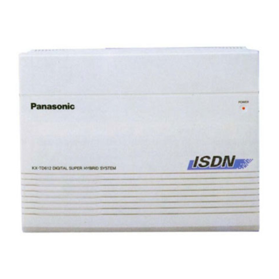
KX-TD612NE / KX-TD61260CE / KX-TD61261G / KX-
2000 Kyushu Matsushita Electric Co., Ltd. All rights reserved.
Unauthorized copying and distribution is a violation of law.
1. INTRODUCTION
1.1. SAFETY PRECAUTIONS
1. Before servicing, unplug the power cord to prevent an electric
shock.
2. When replacing parts, use only the manufacturer's recommended
components.
3. Check the condition of the power cord. Replace if wear or damage
is evident.
TD61280CE / KX-TD61291CE / KX-A227X
1
ORDER NO.KMS0005498C2
Digital Super Hybrid System
(for North Europe)
Advertisement

Related Manuals for Panasonic KX-TD612NE


Summary of Contents for Panasonic KX-TD612NE
- Page 1 ORDER NO.KMS0005498C2 Digital Super Hybrid System KX-TD612NE / KX-TD61260CE / KX-TD61261G / KX- TD61280CE / KX-TD61291CE / KX-A227X (for North Europe) 2000 Kyushu Matsushita Electric Co., Ltd. All rights reserved. Unauthorized copying and distribution is a violation of law. 1. INTRODUCTION 1.1.
- Page 2 4. After servicing, be sure to restore the lead dress, insulation barriers, insulation papers, shields, etc. 5. Before returning the serviced equipment to the customer, be sure to make the following insulation resistance test to prevent the customer from being exposed to shock hazards. 1.2.
- Page 3 Danger of explosion if battery is incorrectly replaced. Replace only with the same or equivalent type recommended by the manufacture. Discard used batteries according to following caution: Disposal of lithium batteries should be performed by permitted, professional disposal firms knowledgeable in state government federal and local hazardous materials and hazardous waste transportation and disposal requirements.
- Page 4 Note: For details of installation, refer to the System Reference Manual. 1.5. SPECIFICATIONS General Description 1. Capacity: ISDN lines / Extension lines 3max. (CO lines 6max.) (12max. with XDP) 2. Control Method: Stored Program CPU: 16 bits CPU 3. Switching: Non Blocking PCM Time Sharing Switch 4.
- Page 5 CHARACTERISTICS 1.Station Loop Limit: KX-T7531/ KX-T7533/ KX-T7536/ KX- 40 ohms T7230/ KX-T7235/ KX-T7250/ KX-T7130/ KX- T7020/ KX-T7050 etc. Single line telephone/ KX-T7310/ etc. 600 ohms including set Doorphone 20 ohms 2.Minimum Leak Resistance: 15000 ohms 3.Maximum Number of Station: 1 for a KX-T7531/ KX-T7533/ KX-T7536/ KX-T7230/ KX-T7235/ KX KX-T7130/ / KX-T7020/ KX-T7050 or a single line telephone.
- Page 6 1.8. DISASSEMBLY INSTRUCTIONS 1.8.1. HOW TO REMOVE THE COVER (Procedure 1) 1. Loosen the screw A. 2. Slide the top upper cabinet to the direction of the / arrow while pressing the marked position. 3. Remove the 2 screws B. 4.
- Page 7 1.8.2. HOW TO REMOVE THE POWER SUPPLY BOARD (Procedure 1 1. Open the upper cabinet. (Refer to steps 1~3 of No.1.8.1.) 2. Remove the 3 screws B. 3. Remove the power unit cover. 4. Pull out the 4 connectors. 5. Remove the 1 screw C. 6.
- Page 8 1.8.3. HOW TO REMOVE THE MAIN BOARD (Procedure 1 1. Pull out the connector. 2. Remove the 2 screws B and D. 3. Remove the main board.
- Page 9 2. KX-TD612NE (MAIN UNIT) 2.1. CIRCUIT OPERATIONS 2.1.1. OUTLIES AND FUNCTIONS OF EACH UNIT In this section, the unit compositions, outlines, and functions of this system are described as...
- Page 10 Classification Board Name Model No. Quantity Remarks Initial Equipment Power Supply Unit KX-TD612NE Main Board KX-TD612NE Option 1 BRI Expansion Card KX-TD61280CE Voice Message Card KX-TD61291CE Doorphone/Dooropener Card for KX-TD61260CE Doorphone KX-T30865 / Dooropener 2port Doorphone/Dooropener Card for KX-TD61261G...
- Page 11 2.1.4. MAIN BOARD The main board has CPU, which control the system, and TSW (Time Switch), which switch the PCM telephone call way, as its main function. Furthermore, the main board has common resources to the systems as clock function, clock making function, and so on. Also, I/F function, which connects the system and the terminal units.
- Page 12 Function Content ISDN Block ISDN circuit interface This is an interface circuit to connect ISDN lines and the Expansion Current Supply Supplies the communicative current to SLT. Block Hook Detection Detects On-Hook and Off-Hook when a bell signal is not Ring Trip Detection Detects Off-hook when a bell signal is presented.
- Page 13 transmitted to the ringing transformer through pin 7 of CN101. 3. AC cut off detection function: AC power failure is detected by R31 - R36, R38, D31-34, C31 and PC2. When AC power is on, pin 4 of PC4 is high. When AC power is turned off, pin 4 of PC2 changes to low.
- Page 14 CPU circuit is mainly composed of following parts. / 16 bit CPU (IC100) / ROM (IC102, IC103, IC104, IC105) / RAM (IC106, IC107) / Gate Array (IC101) etc. / Circuit Operation: CPU(IC100) controls the programs in ROM (IC102, IC103, IC104, IC105), that is, the system.
- Page 15 and of port group #G, which can be able to access by 4 bit. / (f) PCM Highway Controller Function / This function generates the basic timing of PCM Highway, and eight channel pulses. Following are the clocks generated. / CHS0 ~ 4: 128, 64, 32, 16, 8 kHz Channel select signal / CP0 ~ 5: 8 kHz Synchronous signal for CODEC / (g) APT Data Communication Circuit / APT Data Communication...
- Page 16 2. ISDN Block Composition: / ISDN I/F IC (IC500, IC501) / ISDN Transformer (T500, T501) etc. / / Circuit Operation: / This circuit has the S-Bus interface circuit and the ISDN lower LAYER (LAYER 1 only) control circuit. / The component switches B and D channel between the S/T interface and the PCM Highway I/F.
- Page 17 / / / / / / 3. Expansion Block Composition: / This is composed of the following circuits: / (a) Current Supply Circuit / (b) Hook Detection Circuit / (c) Ring Trip Detection Circuit / (d) Bell ringing section / Circuit Operation: / (a) Current Supply Circuit / Current Supply Circuit is constant-current circuit which supplies the call current to SLT.
- Page 18 condition. / Pulse dialing is a input either in the on hook or off hook condition, and the break number (on hook condition) is counted and read as the dial number. / (c) Ring Trip Detection Circuit / This is for detecting off-hook of SLT when the bell signals are presented.
- Page 19 Current supply circuit / (c) Hook detection circuit / (d) 2-4 lines conversion circuit / (e) A/D and D/A conversion circuit (CODEC) IC118 / Circuit Operation: / (a) Circuit for detection whether the Door- Phone is connected or not. / When the Door-Phone is not connected, base of Q105 is high.
- Page 20 connected externally. The control is made by the "DOPEN" signal. One of this circuit are installed on a card. / / Circuit Operation: / When CPU (IC100) make the "DOPEN" signal high, transistor (Q111) controls the relay (RL10) ON. When CPU (IC100) make the "DOPEN"...
- Page 21 presented to HWR1 of the up highway. / / / / 9. Back-Up Circuit Composition: / BAT etc. / / Circuit Operation: / The real time clock in the Gate Array and RAM are backed up by the lithium of secondary battery (BAT) for 7 years.
- Page 22 3. TROUBLESHOOTING GUIDE 3.1. NO OPERATION (Check POWER SUPPLY BOARD, MAIN BOARD) 3.2. NO DIAL TONE (Check MAIN BOARD)
- Page 23 3.3. CAN NOT DIAL (Check MAIN BOARD)
- Page 25 3.4. CAN NOT ACCESS AN EXTENSION (Check MAIN BOARD)
- Page 27 3.5. CAN NOT ACCESS TO ISDN (Check MAIN BOARD) 4. SCHEMATIC DIAGRAM AND PRINTED CIRCUIT BOARD 4.1. SCHEMATIC DIAGRAM(MAIN) 4.2. SCHEMATIC DIAGRAM(MAIN) 5. PRINTED CIRCUIT BOARD...
- Page 28 5.1. MAIN BOARD:COMPONENT VIEW_1 5.2. MAIN BOARD:COMPONENT VIEW_2 5.3. MAIN BOARD:BOTTOM VIEW_1 5.4. MAIN BOARD:BOTTOM VIEW_2 6. SCHEMATIC DIAGRAM AND PRINTED CIRCUIT BOARD 6.1. SCHEMATIC DIAGRAM (POWER UNIT) 7. PRINTED CIRCUIT BOARD 7.1. POWER UNIT:COMPONENT VIEW 8. SEVICE INFORMATION If you do not have the special tools (for example: SPOT HEATER) to remove the SPOT HEATER’S Flat IC, If you have solder (large amount) a soldering iron and a cutter knife, you can easily remove IC’s even though large than 100 pin.
- Page 29 2. Using a cutter, cut the lead at the source. (Cut the contents with the cutter lightly 5 or 6 times.) 3. Remove when the solder melts. (Remove the lead at the same time.) After removing the Flat IC and when attaching the new IC, remove any of the excess solder on the land using the soldering wire, etc.
- Page 30 *Check the accuracy of the IC setting with the corresponding soldering foil. 2. Apply flux for all pins of FLAT PACKAGE IC. 3. Solder using the specified solder, in the direction of the arrow, by sliding the soldering iron. 8.1.4. BRIDGE MODIFICATION PROCEDURE 1.
- Page 31 8.3. IC DATA 8.3.1. CPU (IC100) PORT MAP...
- Page 32 Pin No. Pin Name Function Operation DONEN (Reserved) DACKN (Reserved) DREQN (Reserved) BRG3 (Reserved) DSRN DSRN(RS232C) DTRN DTRN(RS232C) TXD3 TXD(RS232C) RXD3 RXD(RS232C) EX8PDN CODEC(EXT8) Power Control (not used) EX7PDN CODEC(EXT7) Power Control (not used) EX6PDN CODEC(EXT6) Power Control (not used) EX5PDN CODEC(EXT5) Power Control (not used)
- Page 33 Pin No. Pin Name Function Operation DDRCSN Doorphone / Door Opener Card H: negate, L: assert Select UCDCSN Message Card Select H: negate, L: assert USBCSN (Reserved) USBINTN (Reserved) 25HZ 25Hz Bell Signal Output DCALARM DC power down detection H: normal, L: power down SYSTEM CLEAR System Clear input H: normal, L: system clear...
- Page 34 Pin No. Pin Name Function Operation HOOK8 Off-Hook(EXT8) Detection (not used) HOOK7 Off-Hook(EXT7) Detection (not used) HOOK6 Off-Hook(EXT6) Detection (not used) HOOK5 Off-Hook(EXT5) Detection (not used) HOOK4 Off-Hook(EXT4) Detection HOOK3 Off-Hook(EXT3) Detection HOOK2 Off-Hook(EXT2) Detection HOOK1 Off-Hook(EXT1) Detection BELL8 Bell Relay(EXT8) Control (not used) BELL7 Bell Relay(EXT7) Control...
- Page 35 8.5.1. ACTUAL SIZE OF SCREWS...
- Page 36 8.5.2. SHORT PLUG...
- Page 37 8.6. ACCESSORIES AND PACKING MATERIALS...
- Page 39 9. REPLACEMENT PARTS LIST This replacement parts list is for KX-TD612NE only. Refer to the simplified manual (cover) for other areas. Notes: 1. The marking (RTL) indicates that the Retention Time is limited for this item. After the discontinuation of this assembly in production, the item will continue to be available for a specific period of time.
- Page 40 Ref. No. Part No. Part Name & Description Remarks CABINET AND ELECTRICAL PARTS PQHD10011X SMALL SCREW, STEEL PQLB5F2 CORE PQUS141Z SPRING PSGG1017Z1 GRILLE PSGT1883Z NAME PLATE PSHR1146Z LED SPACER PSHR1218Z CLAMPER PSJS02Q10Z CONNECTOR, 2P PSJS02Q11Z CONNECTOR, 2P PSJS07Q97Z CONNECTOR, 7P PSKE1020Y1 POWER UNIT COVER PSKF1030V1...
- Page 41 Ref. No. Part No. Part Name & Description Remarks ACCESSORIES AND PACKING MATERIALS PQHE5004Z TAPPING SCREW, STEEL PQJP1E1Z PLUG PSJS08S08Z CONNECTOR, 8P PSJS10S07Z CONNECTOR, 10P PSQW1480Z LEAFLET for TEMPLATE PSQX1942Z QUICK REFERENCE GUIDE PSQX1943Z QUICK REFERENCE GUIDE PSQW1562Z CE LEAFLET PSQX1970ZCD CD-ROM PSWAT206SP...
- Page 42 Ref. No. Part No. Part Name & Description Remarks IC119 PQVINJM2904V IC121 PSVISNLV74AP IC122 PSVIL5431T IC500 PSVIPS2115F2 IC501 PSVIPS2115F2 IC505 PSVISN7HT00A IC600A PSVIMC14548V IC600B PSVIMC14548V IC600C PSVIMC14548V IC600D PSVIMC14548V IC602 PSVITC4051BT IC603 PSVITC4051BT IC604 PQVILC73872M IC605 PQVILC73872M (TRANSISTORS) Q100 PQVTDTC143E TRANSISTOR(SI) Q101 2SC4081R...
- Page 43 Ref. No. Part No. Part Name & Description Remarks Q602D 2SB1322 TRANSISTOR(SI) Q603A 2SD1994A TRANSISTOR(SI) Q603B 2SD1994A TRANSISTOR(SI) Q603C 2SD1994A TRANSISTOR(SI) Q603D 2SD1994A TRANSISTOR(SI) Q604A 2SC4081R TRANSISTOR(SI) Q604B 2SC4081R TRANSISTOR(SI) Q604C 2SC4081R TRANSISTOR(SI) Q604D 2SC4081R TRANSISTOR(SI) Q605A PQVTDTC143E TRANSISTOR(SI) Q605B PQVTDTC143E TRANSISTOR(SI) Q605C...
- Page 44 Ref. No. Part No. Part Name & Description Remarks D600A MA143 DIODE(SI) D600B MA143 DIODE(SI) D600C MA143 DIODE(SI) D600D MA143 DIODE(SI) D600E MA143 DIODE(SI) D600F MA143 DIODE(SI) D600G MA143 DIODE(SI) D600H MA143 DIODE(SI) D601A PSVDUDZ20B DIODE(SI) D601B PSVDUDZ20B DIODE(SI) D601C PSVDUDZ20B DIODE(SI) D601D...
- Page 45 Ref. No. Part No. Part Name & Description Remarks L114 PQLE106 COIL L500 PQLQR1T2R2M COIL L501 PQLQR1T2R2M COIL L504 PQLQR2BT COIL L505 PQLQR2BT COIL L600A PQLE106 COIL L600B PQLE106 COIL L600C PQLE106 COIL L600D PQLE106 COIL L600E PQLE106 COIL L600F PQLE106 COIL L600G...
- Page 46 Ref. No. Part No. Part Name & Description Remarks R226 PQLQR1RM601 COIL R227 PQLQR1RM601 COIL R228 PQLQR1RM601 COIL R229 PQLQR1RM601 COIL R230 PQLQR1RM601 COIL R231 PQLQR1RM601 COIL R232 PQLQR1RM601 COIL R233 PQLQR1RM601 COIL R237 PQLQR1RM601 COIL R238 PQLQR1RM601 COIL R239 PQLQR1RM601 COIL R240...
- Page 47 Ref. No. Part No. Part Name & Description Remarks R311 PQLQR1RM601 COIL R312 PQLQR1RM601 COIL R313 PQLQR1RM601 COIL R314 PQLQR1RM601 COIL R315 PQLQR1RM601 COIL R317 PQLQR1RM601 COIL R318 PQLQR1RM601 COIL R319 PQLQR1RM601 COIL R320 PQLQR1RM601 COIL R321 PQLQR1RM601 COIL R322 PQLQR1RM601 COIL R323...
- Page 48 Ref. No. Part No. Part Name & Description Remarks R457 PQLQR1RM601 COIL R488 PQLQR1RM601 COIL (CONNECTORS) PQJP7D68Z CONNECTOR, 7P PSJS48A93Z CONNECTOR, 48P PSJS44A94Z CONNECTOR, 44P PSJP30A62Z CONNECTOR, 30P PQJS06A15Z CONNECTOR, 6P PSJP09A64Z CONNECTOR, 9P PSJP09B10Z CONNECTOR, 9P CN600 PSJP08B06Z CONNECTOR, 8P CN601 PSJP08B06Z CONNECTOR, 8P...
- Page 49 Ref. No. Part No. Part Name & Description Remarks (PHOTO ELECTRIC TRANSDUCER) PC10 0N3181R PHOTO ELECTRIC TRANSDUCER (SWITCHES) EVQ21409K SWITCH, RESET ESD11V120 SWITCH, CLEAR, NORMAL (TRANSFORMERS) PSLT8D7A TRANSFORMER PSLT9H6CF1A TRANSFORMER PSLT2D6A TRANSFORMER T500 PSLT9Z15A TRANSFORMER T501 PSLT9Z15A TRANSFORMER T600A PSLT9Z4A TRANSFORMER T600B PSLT9Z4A...
- Page 50 Ref. No. Part No. Part Name & Description Remarks ZNR10 PQVDNV039D03 VARISTOR ZNR60A PQVDNV039D03 VARISTOR ZNR60B PQVDNV039D03 VARISTOR ZNR60C PQVDNV039D03 VARISTOR ZNR60D PQVDNV039D03 VARISTOR ZNR60E PQVDNV039D03 VARISTOR ZNR60F PQVDNV039D03 VARISTOR ZNR60G PQVDNV039D03 VARISTOR ZNR60H PQVDNV039D03 VARISTOR ZNR61A PQVDNV039D03 VARISTOR ZNR61B PQVDNV039D03 VARISTOR ZNR61C PQVDNV039D03 VARISTOR...
- Page 51 Ref. No. Part No. Part Name & Description Remarks R124 ERJ3GEYJ330 R125 ERJ3GEYJ330 R126 ERJ3GEYJ330 R127 ERJ3GEYJ330 R128 ERJ3GEYJ330 R129 ERJ3GEYJ330 R130 ERJ3GEYJ330 R131 ERJ3GEYJ330 R132 ERJ3GEYJ330 R133 ERJ3GEYJ473 R134 ERJ3GEYJ473 R135 ERJ3GEYJ473 R136 ERJ3GEYJ473 R137 ERJ3GEYJ473 R138 ERJ3GEYJ473 R139 ERJ3GEYJ473 R140 ERJ3GEYJ472...
- Page 52 Ref. No. Part No. Part Name & Description Remarks R174 ERJ3GEYJ473 R176 ERJ3GEYJ473 R177 ERJ3GEYJ473 R178 ERJ3GEYJ473 R179 ERJ3GEYJ473 R180 ERJ3GEYJ473 R181 ERJ3GEYJ473 R182 ERJ3GEYJ473 R183 ERJ3GEYJ473 R184 ERJ3GEYJ473 R185 ERJ3GEYJ473 R186 ERJ3GEYJ473 R187 ERJ3GEYJ473 R188 ERJ3GEYJ473 R189 ERJ3GEYJ473 R190 ERJ3GEYJ473 R191 ERJ3GEYJ473...
- Page 53 Ref. No. Part No. Part Name & Description Remarks R263 ERJ3GEYJ330 R264 ERJ3GEYJ330 R265 ERJ3GEYJ330 R266 ERJ3GEYJ330 R267 ERJ3GEYJ330 R268 ERJ3GEYJ330 R269 ERJ3GEYJ272 2.7K R270 ERJ3GEYJ103 R271 ERJ3GEYJ103 R279 ERJ3GEYJ470 R280 ERJ3GEYJ470 R282 ERJ3GEYJ473 R283 ERJ3GEYJ473 R284 ERJ3GEYJ473 R285 ERJ3GEYJ473 R286 ERJ3GEYJ473 R287...
- Page 54 Ref. No. Part No. Part Name & Description Remarks R384 ERJ3GEYJ473 R385 PQ4R10XJ472 4.7K R386 ERJ3GEYJ124 120K R387 ERJ3GEYJ563 R388 ERJ3GEYJ154 150K R389 ERJ3GEYJ393 R390 ERJ3GEYJ223 R391 ERJ3GEYJ223 R400 ERJ3GEYJ103 R401 ERJ3GEYJ184 180K R402 ERJ3GEYJ203 R403 ERJ3GEYJ394 390K R404 ERJ3GEYJ333 R405 ERJ3GEYJ473 R406...
- Page 55 Ref. No. Part No. Part Name & Description Remarks R441 ERJ14YJ151 R442 ERJ14YJ151 R443 ERJ14YJ151 R444 ERJ14YJ151 R445 ERJ3GEYJ330 R446 ERJ3GEYJ330 R448 ERJ3GEYJ473 R449 ERJ3GEYJ473 R450 ERJ3GEYJ473 R451 ERJ3GEYJ473 R452 ERJ3GEYJ473 R454 ERJ3GEYJ470 R455 ERJ3GEYJ473 R456 ERJ3GEYJ473 R458 ERJ3GEYJ821 R459 ERJ3GEYJ821 R460 ERJ3GEYJ821...
- Page 56 Ref. No. Part No. Part Name & Description Remarks R514 ERJ3GEYJ473 R515 ERJ3GEYJ473 R516 ERJ3GEYJ101 R517 ERJ3GEYJ272 2.7K R518 ERJ3GEYJ272 2.7K R519 ERJ3GEYJ473 R520 ERJ3GEYJ101 R521 ERJ3GEYJ473 R522 ERJ3GEYJ473 R523 ERJ3GEYJ473 R524 ERJ3GEYJ822 8.2K R525 ERJ3GEYJ822 8.2K R526 ERJ3GEYJ822 8.2K R527 ERJ3GEYJ822 8.2K...
- Page 57 Ref. No. Part No. Part Name & Description Remarks R604D ERJ3GEYJ561 R604E ERJ3GEYJ561 R604F ERJ3GEYJ561 R604G ERJ3GEYJ561 R604H ERJ3GEYJ561 R605A ERJ3GEYJ222 2.2K R605B ERJ3GEYJ222 2.2K R605C ERJ3GEYJ222 2.2K R605D ERJ3GEYJ222 2.2K R605E ERJ3GEYJ222 2.2K R605F ERJ3GEYJ222 2.2K R605G ERJ3GEYJ222 2.2K R605H ERJ3GEYJ222 2.2K...
- Page 58 Ref. No. Part No. Part Name & Description Remarks R613A ERJ3GEYJ103 R613B ERJ3GEYJ103 R613C ERJ3GEYJ103 R613D ERJ3GEYJ103 R614A PQ4R10XJ470 R614B PQ4R10XJ470 R614C PQ4R10XJ470 R614D PQ4R10XJ470 R615A ERDS2TJ680 R615B ERDS2TJ680 R615C ERDS2TJ680 R615D ERDS2TJ680 R616A ERJ3GEYJ101 R616B ERJ3GEYJ101 R616C ERJ3GEYJ101 R616D ERJ3GEYJ101 R617A ERJ3GEYJ471...
- Page 59 Ref. No. Part No. Part Name & Description Remarks R626B ERJ3GEYJ471 R626C ERJ3GEYJ471 R626D ERJ3GEYJ471 R627A ERJ3GEYJ104 100K R627B ERJ3GEYJ104 100K R627C ERJ3GEYJ104 100K R627D ERJ3GEYJ104 100K R628A ERJ3EKF7872 78.7K R628B ERJ3EKF7872 78.7K R628C ERJ3EKF7872 78.7K R628D ERJ3EKF7872 78.7K R629A ERJ3EKF7872 78.7K R629B...
- Page 60 Ref. No. Part No. Part Name & Description Remarks R638C ERJ3GEYJ391 R638D ERJ3GEYJ391 R639 PQ4R10XJ473 R640 PQ4R10XJ152 1.5K R641 ERJ3GEYJ394 390K R642 ERJ3GEYJ394 390K (CAPACITORS) C101 ECUV1C104KBV 0.1 C102 ECUV1C104KBV 0.1 C103 ECUV1C104KBV 0.1 C104 ECUV1C104KBV 0.1 C105 ECUV1C104KBV 0.1 C106 ECUV1H470JCV C107...
- Page 61 Ref. No. Part No. Part Name & Description Remarks C143 ECUV1H100DCV 10P C144 ECUV1H100DCV 10P C145 ECUV1H100DCV 10P C146 ECUV1H100DCV 10P C147 ECUV1H100DCV 10P C149 ECUV1H470JCV C150 ECUV1H470JCV C151 ECUV1H470JCV C152 ECUV1H470JCV C153 ECUV1H100DCV 10P C154 ECUV1H470JCV C155 ECUV1H100DCV 10P C156 ECUV1H470JCV C157...
- Page 62 Ref. No. Part No. Part Name & Description Remarks C199 ECUV1C563KBV 0.056 C200 ECEA1EU470 C201 ECEA1HKS4R7 C202 PSCUV2EY104K C203 PSCUV2EY104K C204 PSCUV2EY104K C205 PSCUV2EY104K C206 ECUV1C823KBV 0.082 C207 ECUV1C823KBV 0.082 C208 ECEA1HN3R3S C209 ECUV1H100DCV 10P C210 ECEA1HU330 C211 ECEA1HU330 C212 EEUFC1H221SB C213 ECQV1H104JZ...
- Page 63 Ref. No. Part No. Part Name & Description Remarks C259 ECUV1C104KBV 0.1 C260 ECUV1C104KBV 0.1 C261 ECUV1C104KBV 0.1 C262 ECUV1C104KBV 0.1 C263 ECUV1C104KBV 0.1 C264 ECUV1C104KBV 0.1 C265 ECUV1C104KBV 0.1 C266 ECUV1C104KBV 0.1 C270 ECEA1AU101 C271 ECEA1AU221 C272 ECEA1AU331 C500 ECUV1H330JCV C501 ECUV1H330JCV...
- Page 64 Ref. No. Part No. Part Name & Description Remarks C602H PQCUV1H105JC 1 C603A PQCUV1H105JC 1 C603B PQCUV1H105JC 1 C603C PQCUV1H105JC 1 C603D PQCUV1H105JC 1 C603E PQCUV1H105JC 1 C603F PQCUV1H105JC 1 C603G PQCUV1H105JC 1 C603H PQCUV1H105JC 1 C604A ECUV1H680JCV C604B ECUV1H680JCV C604C ECUV1H680JCV C604D...
- Page 65 Ref. No. Part No. Part Name & Description Remarks C614A PQCUV1C474KB 0.47 C614B PQCUV1C474KB 0.47 C614C PQCUV1C474KB 0.47 C614D PQCUV1C474KB 0.47 C615A PQCUV1C184KB 0.18 C615B PQCUV1C184KB 0.18 C615C PQCUV1C184KB 0.18 C615D PQCUV1C184KB 0.18 C617A ECUV1H221JCV 220P C617B ECUV1H221JCV 220P C617C ECUV1H221JCV 220P C617D...
- Page 66 Ref. No. Part No. Part Name & Description Remarks POWER SUPPLY BORD PARTS PCB2 PSLP1074Y POWER SUPPLY BOARD ASSY (RTL) (ICS) AN8021L IC101 PSVIPQ1CF2 IC301 PQVILA6500 IC304 PQVILA6500 (TRANSISTORS) PSVTFS7KM18A TRANSISTOR(SI) 2SC1740S TRANSISTOR(SI) Q101 2SC1740S TRANSISTOR(SI) Q150 2SC1740S TRANSISTOR(SI) Q201 2SC1740S TRANSISTOR(SI) Q202...
- Page 67 Ref. No. Part No. Part Name & Description Remarks D207 1SS133 DIODE(SI) D208 1SS133 DIODE(SI) D209 1SS133 DIODE(SI) D210 PSVDHZS202 DIODE(SI) D301 PSVDHZS12A2 DIODE(SI) (COILS) BEA1 PSLEBL02RN1 COIL BEA2 PSLEBL02RN2 COIL BEA101 PSLEBL02RN2 COIL BEA103 PSLEBL01RN1 COIL ELF19N016A COIL L101 PSLESK08MS5Y COIL (CONNECTOR AND SOCKET) PSJPNC18710N...
- Page 68 Ref. No. Part No. Part Name & Description Remarks (VARIABLE RESISTORS) VR101 EVNDXAA03B53 VARIABLE RESISTOR VR102 EVNDXAA03B13 VARIABLE RESISTOR (VARISTOR) PSVDENC471D7 VARISTOR (RESISTORS) ERDS1TJ564 560K ERDS2TJ220 ERDS2TJ273 ERDS2TJ161 ERDS2TJ820 ERDS2TJ821 PSBPR38F022 0.22 ERDS2TJ103 ERDS2TJ473 ERDS2TJ104 100K ERG1SJ470 ERG2SJ103 ERG2SJ103 ERG2SJ103 ERDS2TJ824 820K ERDS2TJ824...
- Page 69 Ref. No. Part No. Part Name & Description Remarks R205 ERDS2TJ472 4.7K R206 ERDS2TJ472 4.7K R207 ERG2SJ152 1.5K R210 ERX2SJ6R8 R212 ERX2SJ6R8 R214 ERDS2TJ102 R215 ERDS2TJ102 R301 ERG2SJ101 R302 ERDS2TJ222 2.2K R303 ERDS2TJ272 2.7K R304 ERDS2TJ392 3.9K R305 ERDS2TJ103 R306 ERDS2TJ2R2 R307 ERDS2TJ2R2...
- Page 70 Ref. No. Part No. Part Name & Description Remarks FIXTURES AND TOOLS PQZZ2K7Z EXTENSION CORD, 2P PQZZ2K13Z EXTENSION CORD, 2P PQZZ7K4Z EXTENSION CORD, 7P Note: The Extension Cords are useful for servicing. / (They make servicing easy.) 10. KX-TD61260CE / (DOORPHONE / DOOROPENER CARD for T30865)
- Page 71 10.1. LOCATION OF OPTIONAL CARDS The location of optional cards is shown below. / / Precaution: To protect the printed circuit boards (PCB) from static electricity. / Do not touch parts on the PCB in the main unit and on the optional cards.
- Page 72 10.2. BLOCK DIAGRAM...
- Page 73 10.3. EXPLANATION OF BLOCK DIAGRAM / CIRCUIT OPERATION 10.3.1. OPTION CARD (KX-TD61260CE) Composition: / This Doorphone card is composed of the control interface with KX-TD612 and two doorphone interface and two dooropener interface section. / 1. Doorphone Section This card has two door phone interfaces. / This door phone intercom pass is composed of the send amplifier and receive amplifier circuits.
- Page 74 10.4. TROUBLESHOOTING GUIDE 10.4.1. CAN NOT CALL FROM DOORPHONE 10.4.2. CAN NOT TALK 10.4.3. CAN NOT USE DOOROPENER...
- Page 75 10.5. SCHEMATIC DIAGRAM 10.6. PRINTED CIRCUIT BOARD (COMPONENT VIEW) 10.7. SERVICE INFORMATION 10.7.1. TERMINAL GUIDE OF ICS, TRANSISTORS AND DIODES 10.7.2. IC DATA 10.7.2.1. PARALLEL I/O (IC800) PORT MAP Pin No. Pin Name Function Operation CARD CODE2 Card detection and code. L:German L:T30865 H CARD CODE1 Card detection and code.
- Page 76 Pin No. Pin Name Function Operation DRPDN-2 CODEC(for Door-phone2) H: power on, L: power power control DRPDN-1 CODEC(for Door-phone1) H: power on, L: power power control 10.7.3. ACCESSORIES AND PACKING MATERIALS 11. REPLACEMENT PARTS LIST This replacement parts list is for KX-TD61260CE only. Refer to the simplified manual (cover) for other areas.
- Page 77 special characteristics important for safety. When replacing any of these components, use only manufacture's specified parts. 3. The S mark indicates service standard parts and may differ from production parts. 4. RESISTORS & CAPACITORS / Unless otherwise specified; / All resistors are in ohms ( ) K=1000 , M=1000k / All capacitors are in MICRO FARADS (...
- Page 78 Ref. No. Part No. Part Name & Description Remarks MAIN BOARD PARTS (ICS) IC800 PQVIMS8C5A2K IC IC801 PQVITC7SU04F IC802A PQVIMC45503W IC IC802B PQVIMC45503W IC IC803A PQVINJM2904V IC803B PQVINJM2904V IC805 PQVITC7SU04F IC806 PQVINJM2904V (TRANSISTORS) Q800A PQVTDTC124EU TRANSISTOR(SI) Q800B PQVTDTC124EU TRANSISTOR(SI) Q801A UN521DTX TRANSISTOR(SI) Q801B...
- Page 79 Ref. No. Part No. Part Name & Description Remarks RL801B PSSLJV12KTZ RELAY (TRANSFORMERS) T800A PSLT8D7A TRANSFORMER T800B PSLT8D7A TRANSFORMER (VARISTORS) ZNR80A PQVDNV039D03 VARISTOR ZNR80B PQVDNV039D03 VARISTOR (RESISTORS) R800A PQ4R10XJ563 R800B PQ4R10XJ563 R801A PQ4R10XJ102 R801B PQ4R10XJ102 R802A ERJ14YJ151 R802B ERJ14YJ151 R803A PQ4R10XJ182 1.8K R803B...
- Page 80 Ref. No. Part No. Part Name & Description Remarks R822 PQ4R10XJ330 R823 PQ4R10XJ330 R824 PQ4R10XJ330 R825 PQ4R10XJ330 R826 PQ4R10XJ330 R827 PQ4R10XJ330 R828 PQ4R10XJ330 R829 PQ4R10XJ330 R830 PQ4R10XJ330 R831 PQ4R10XJ330 R832 PQ4R10XJ330 R833 PQ4R10XJ330 R834 PQ4R10XJ330 R835 PQ4R10XJ330 R836 PQ4R10XJ330 R837 PQ4R10XJ473 R838 PQ4R10XJ473...
- Page 81 Ref. No. Part No. Part Name & Description Remarks C821 PQCUV1E104MD 0.1 C822 ECEA1HU330 C823 ECEA1AU221 C824 PQCUV1E104MD 0.1 C829 PQCUV1E104MD 0.1 C830 ECEA1EU101 C831 PQCUV1E104MD 0.1 C832 PQCUV1E104MD 0.1 C832A PQCUV1E104MD 0.1 C832B PQCUV1E104MD 0.1 C833 PQCUV1E104MD 0.1 C834 ECEA1AU221 C835 ECEA1AU221...
- Page 82 12.1. LOCATION OF OPTIONAL CARDS The location of optional cards is shown below. / / Precaution: To protect the printed circuit boards (PCB) from static electricity. / Do not touch parts on the PCB in the main unit and on the optional cards.
- Page 83 12.2. BLOCK DIAGRAM...
- Page 84 12.3. EXPLANATION OF BLOCK DIAGRAM / CIRCUIT OPERATION 12.3.1. OPTION CARD (KX-TD61261G) Composition: / This Doorphone card is composed of the control interface with KX-TD612 and two doorphone interface and two dooropener interface section. / 1. Doorphone Section This card has two door phone interfaces. / This door phone intercom pass is composed of the send amplifier and receive amplifier circuits which are included in CODEC IC.
- Page 85 used for the door opener SW. 12.4. TROUBLESHOOTING GUIDE 12.4.1. CAN NOT CALL FROM DOORPHONE 12.4.2. CAN NOT TALK 12.4.3. CAN NOT USE DOOROPENER 12.5. SCHEMATIC DIAGRAM...
- Page 86 12.6. PRINTED CIRCUIT BOARD (COMPONENT VIEW) 12.7. SERVICE INFORMATION 12.7.1. TERMINAL GUIDE OF ICS, TRANSISTORS AND DIODES 12.7.2. IC DATA 12.7.2.1. PARALLEL I/O (IC800) PORT MAP Pin No. Pin Name Function Operation CARD CODE2 Card detection and code. L:German L:T30865 H: CARD CODE1 Card detection and code.
- Page 87 13. REPLACEMENT PARTS LIST This replacement parts list is for KX-TD61261G only. Refer to the simplified manual (cover) for other areas. Notes: 1. The marking (RTL) indicates that the Retention Time is limited for this item. After the discontinuation of this assembly in production, the item will continue to be available for a specific period of time.
- Page 88 are in MICRO FARADS ( F) P= F / *Type & Wattage of Resistor 13.1. ACCESSORIES AND PACKING MATERIALS Ref. No. Part No. Part Name & Description Remarks ACCESSORIES AND PACKING MATERIALS PQLB5D1 CORE PSJS08S06Z CONNECTOR, 8P PSJS30Q94Z CONNECTOR, 30P XYN3+F12FN SCREW WITH WASHER, STEEL PSPK1436Z...
- Page 89 Ref. No. Part No. Part Name & Description Remarks MAIN BOARD PARTS (ICS) IC850 PQVIMS8C5A2K IC IC851 PQVITC7SU04F IC852A PQVIMC45503W IC IC852B PQVIMC45503W IC IC853 PQVITC7SU04F (TRANSISTORS) Q851A UN5213 TRANSISTOR(SI) Q851B UN5213 TRANSISTOR(SI) Q852A PQVTDTC143E TRANSISTOR(SI) Q852B PQVTDTC143E TRANSISTOR(SI) Q853A PQVTDTC143E TRANSISTOR(SI) Q853B...
- Page 90 Ref. No. Part No. Part Name & Description Remarks (RESISTORS) R850A ERJ14YJ151 R850B ERJ14YJ151 R851A ERJ14YJ822 8.2K R851B ERJ14YJ822 8.2K R852A ERJ14YJ822 8.2K R852B ERJ14YJ822 8.2K R853A ERJ14YJ151 R853B ERJ14YJ151 R854A ERJ14YJ102 R854B ERJ14YJ102 R855A PQ4R10XJ223 R855B PQ4R10XJ223 R857A ERJ14YJ102 R857B ERJ14YJ102 R858A...
- Page 91 Ref. No. Part No. Part Name & Description Remarks R887 PQ4R10XJ330 R888 PQ4R10XJ330 R889 PQ4R10XJ330 R890 PQ4R10XJ330 R891 PQ4R10XJ330 R892 PQ4R10XJ473 R893 PQ4R10XJ473 (CAPACITORS) C850A ECEA1EKN4R7 C850B ECEA1EKN4R7 C851A ECEA1EKN4R7 C851B ECEA1EKN4R7 C852A PSCUV2EY104K 0.1 C852B PSCUV2EY104K 0.1 C853A PSCUV2EY104K 0.1 C853B PSCUV2EY104K 0.1 C854A...
- Page 92 14.1. LOCATION OF OPTIONAL CARDS The location of optional cards is shown below. / / Precaution: To protect the printed circuit boards (PCB) from static electricity. / Do not touch parts on the PCB in the main unit and on the optional cards.
- Page 93 14.2. BLOCK DIAGRAM...
- Page 94 14.3. EXPLANATION OF BLOCK DIAGRAM / CIRCUIT OPERATION 14.3.1. OPTION CARD (KX-TD61280CE) Composition: / ISDN I/F IC (IC700) / ISDN Transformer (T700) / Circuit Operation: / This circuit has the S-Bus interface circuit and the ISDN lower LAYER (LAYER 1 only) control circuit. / The component switches B and D channel between the S/T interface and the PCM Highway I/F.
- Page 95 14.4. TROUBLESHOOTING GUIDE 14.4.1. CAN NOT ACCESS TO ISDN...
- Page 96 14.5. SCHEMATIC DIAGRAM 14.6. PRINTED CIRCUIT BOARD (COMPONENT VIEW) 14.7. SERVICE INFORMATION 14.7.1. TERMINAL GUIDE OF ICS, TRANSISTORS AND DIODES 14.7.2. ACCESSORIES AND PACKING MATERIALS...
- Page 97 15. REPLACEMENT PARTS LIST This replacement parts list is for KX-TD61280CE only. Refer to the simplified manual (cover) for other areas. Notes: 1. The marking (RTL) indicates that the Retention Time is limited for this item. After the discontinuation of this assembly in production, the item will continue to be available for a specific period of time.
- Page 98 15.1. ACCESSORIES AND PACKING MATERIALS Ref. No. Part No. Part Name & Description Remarks ACCESSORIES AND PACKING MATERIALS PSHR1202Z SPACER PSPK1655Z GIFT BOX PSPP1048Z PROTECTION COVER XZB05X08A03 PROTECTION COVER PSQA2149Z MODEL NO.LABEL 15.2. MAIN BOARD PARTS Ref. No. Part No. Part Name &...
- Page 99 Ref. No. Part No. Part Name & Description Remarks (CONNECTORS) CN700 PSJP48B13Z CONNECTOR, 48P CN701 PSJP06B14Z CONNECTOR, 6P PLUG 1 PQJS02S12Z CONNECTOR, 2P PLUG 2 PSJS02S09Z CONNECTOR, 2P SW700 PQJP03G47X CONNECTOR, 3P SW701 PQJP03G47X CONNECTOR, 3P SW702 PQJP03G47X CONNECTOR, 3P SW703 PQJP03G47X CONNECTOR, 3P...
- Page 100 Ref. No. Part No. Part Name & Description Remarks (CAPACITORS) C700 ECUV1H330JCV 33P C701 ECUV1H330JCV 33P C702 ECUV1C104KBV 0.1 C703 ECUV1C104KBV 0.1 C704 ECUV1C104KBV 0.1 C705 ECUV1H102KBV 0.001 C706 ECUV1C104KBV 0.1 C707 ECUV1C104KBV 0.1 C708 ECUV1H470JCV 47P 16. KX-TD61291CE / (Voice Message CARD)
- Page 101 16.1. LOCATION OF OPTIONAL CARDS The location of optional cards is shown below. / / Precaution: To protect the printed circuit boards (PCB) from static electricity. / Do not touch parts on the PCB in the main unit and on the optional cards.
- Page 102 16.3. EXPLANATION OF BLOCK DIAGRAM / CIRCUIT OPERATION 16.3.1. OPTION CARD (KX-TD61291CE) Composition: / DSP IC (IC14, IC15) / Flash ROM (IC10, IC12) / Circuit Operation: / This card has two voice message circuits. The voice message circuit is composed of DSP and Flash ROM. / DSP has the functions that PCM recording and playback, voice prompting, tone detection and generation.
- Page 103 16.4.1. NO OPERATION 16.5. SCHEMATIC DIAGRAM 16.6. PRINTED CIRCUIT BOARD 16.7. SERVICE INFORMATION 16.7.1. TERMINAL GUIDE OF ICS, TRANSISTORS AND DIODES 16.7.2. ACCESSORIES AND PACKING MATERIALS...
- Page 104 17. REPLACEMENT PARTS LIST This replacement parts list is for KX-TD61291CE only. Refer to the simplified manual (cover) for other areas. Notes: 1. The marking (RTL) indicates that the Retention Time is limited for this item. After the discontinuation of this assembly in production, the item will continue to be available for a specific period of time.
- Page 105 17.1. ACCESSORIES AND PACKING MATERIALS Ref. No. Part No. Part Name & Description Remarks ACCESSORIES AND PACKING MATERIALS PSHR1202Z LOCK SPACER PSPK1655Z GIFT BOX PSPP1048Z PROTECTION COVER XZB05X08A03 PROTECTION COVER PSQA2151Z MODEL NO.LABEL 17.2. MAIN BOARD PARTS Ref. No. Part No. Part Name &...
- Page 106 Ref. No. Part No. Part Name & Description Remarks (RESISTORS) ERJ3GEYJ473 ERJ3GEYJ473 ERJ3GEYJ473 ERJ3GEYJ105 ERJ3GEYJ105 ERJ3GEY0R00 ERJ3GEY0R00 ERJ3GEY0R00 ERJ3GEY0R00 ERJ3GEY0R00 ERJ3GEY0R00 ERJ3GEY0R00 ERJ3GEY0R00 ERJ3GEY0R00 ERJ3GEY0R00 ERJ3GEY0R00 ERJ3GEY0R00 ERJ3GEY0R00 ERJ3GEY0R00 (CAPACITORS) ECUV1C104KBV 0.1 ECUV1C104KBV 0.1 ECUV1H010CCV 1P ECUV1H010CCV 1P ECUV1H010CCV 1P ECUV1H010CCV 1P ECUV1C104KBV 0.1 ECUV1C104KBV 0.1...
- Page 107 18.1. SERVICE INFORMATION 18.1.1. ACCESSORIES AND PACKING MATERIALS...
- Page 108 19. REPLACEMENT PARTS LIST This replacement parts list is for KX-A227X only. Refer to the simplified manual (cover) for other areas. Notes: 1. The marking (RTL) indicates that the Retention Time is limited for this item. After the discontinuation of this assembly in production, the item will continue to be available for a specific period of time.
- Page 109 Ref. No. Part No. Part Name & Description Remarks ACCESSORIES AND PACKING MATERIALS PSJS02Q48Y CABLE XB40M10M10 LEAD WIRE PSBA2F31NM10 FUSE XZB06X10A05 PROTECTION COVER PSQW1387ZA LEAFLET PSPK1524Z GIFT BOX PSQA1964Z MODEL No. LABEL H (Q) KXTD612NE / KXTD61260CE / KXTD61261G / KXTD61280CE / KXTD61291CE / KXA227X / Printed in Japan...
- Page 110 16 s µ 440V LINE INRUSH CURRENT CN104 SURGE OVER DISCHARGE FILTER PROTECTION ABSORBER BEA101 C109 PROTECTION NTC1 TO BACK UP 1kV1500P BATTERY CHARGE/DISCHAGE CIRCUIT BATTERY LIVE AC250VT4A CN103 D101 24VH SHORT CIRCUIT NTC2 PROTECTION NTTEURAL Q204 R204 4700P SWITCHING OVERCHARGE MOS FET PROTECTION...
- Page 111 R153 R152 CN101 R150 R305 Q150 CN104 R304 R151 J105 C104 NTC2 IC301 R114 R110 VR101 BEA103 R121 R112 C103 R111 CN102 Q101 Bell R120 BEA2 VR102 R116 R306 C110 D3 D5 IC101 D111 R301 C302 R113 R303 L101 J104 R302 CN103 D102...
- Page 112 CN800 R820 33 HWS[1] R821 33 HWR[1] IC805 R822 33 For T30865 4MHZ 4MHz R823 33 READY (CONECTED) READY (CONECTED) : 5V : 5V CP[4] DOOR PHONE READY DOOR PHONE READY READY (NOT CONECTED) : 0V READY (NOT CONECTED) : 0V DREADY1 8kHz Q801A...
- Page 113 D800 Q804 R803 C803 C805 C822 C823 R811 C806 C801 R804 CN800 C808 RL801 C807 C802 D801 C811 Q802 Q803 C804 R802 Q805 R805 Opener R800 R807 R810 R817 R823 R812 R808 R815 R820 Q801 R801 R813 R822 L801 IC803 CN801 R821 C809...
- Page 114 For German type CODEC IC852A CN850 R867A R875 HWS1 DR 8 HWS[1] R876 100K HWR1 DT 13 HWR[1] IC853 R877 4MHz MCLK 4MHZ BCLKR 9 R858A BCLKT 12 4MHz 8kHz -law : 5V FSR 7 A-law : 0V R878 FST 14 CP[4] MU/AN MU/AN...
- Page 115 Q853 C857 R869 R868 R860 C856 RL851 C862 C863 CN850 C858 C853 D852 Opener R859 R853 R857 R864 C859 Q851 R852 R865 IC852 R856 R862 Call R851 Q852 R855 R863 R892 IC851 CN851 R858 R866 C852 C855 C854 IC853 Control RL850 R861 R867 D851...
- Page 116 CN701 ISDN I/F ISDN TRANSFORMER SW700 R704 IC700 CN700 T700 SXL[1] HWR[1] PCMOUT PCMIN D700 D703 R708 HWS[1] 2.7K SW701 R705 LICLK SXL[2] R709 IFH[1] 2.7K R702 R706 4MHz 7.98MHz SRL[2] 8.2K 1.8K WELN SW702 D704 D707 SRL[1] S0CSN[2] R703 R707 R714 8.2K...
- Page 117 3 SW701 C704 D702 D701 R705 R700 SW700 C705 D703 D700 C707 3 SW702 C700 R704 IC700 C702 R706 R703 T700 R707 SW703 C701 IC701 D706 D705 C703 L701 R701 L700 R702 R712 R711 R709 D707 D704 C706 R710 R708 IC702 SW705 R713...
- Page 118 2MHZ,CP[0-1],HWR[1],HWS[1],LA[1-2] LD[0-7] CN10 LD[0] LD[0] LD[1] FLASH ROM LD[1] IC19 IC10 IC14 LD[2] LD[0] LD[2] HDB0 HOSTDB0 LD[1] LD[3] HDB1 HOSTDB1 LD[2] LD[3] HDB2 HOSTDB2 LD[3] LD[4] HDB3 HOSTDB3 LD[4] LD[4] HDB4 HOSTDB4 LD[5] LD[5] HDB5 HOSTDB5 LD[6] LD[5] HDB6 HOSTDB6 LD[7] LD[6]...
- Page 119 (COMPONENT VIEW) IC15 IC10 IC14 IC12 IC18 IC19 IC17 R24 R26 R28 IC16 R25 R27 CN10 (BOTTOM VIEW)
- Page 120 Front Bell Panel Trans. JACK1-2 -15V Pulse TXA [0-7], TXB [0-7], RXI [0-7] Data Comm. Trans. Circuit 25Hz Pulse Bell Amp [A/DPITS Circuit] 25Hz Bell Gate AC230V switch PAYTONE[1-4] 16kHz Paytone Array Current Supply +24V Power HWS2, HWR2 DC-DC CODEC Supply Ring -15V...
- Page 121 LA[1-23] 2:3B;2:4B;2:1H;2:1B 10G;2:4B;2:3C;2:1H;2:1B LD[0-15] IC111 S0CSN[0] IC101 2:1H SOCSN0 SCSN0 S0CSN[1] R207 LA[1] 2:1H SOCSN1 SCSN1 STO0 S0CSN[2] R208 LA[2] IC105 IC103 2:1G SOCSN2 LA15 STI0 HWS[1] R263 R209 LA[3] LA[1] LD[0] LA[1] LD[0] 3C;9E;4F;2:1I;2:4A;2:3B STO1 HWR[1] R264 R210 LA[4] +5V2 IC100 LA[2]...
- Page 122 ISDN 4MHz CN600 T600A R504 L600A CN500 T500 IC500 R601A 2.2K HWR[1] HWR[1] PCMOUT 1:8H;1:3C;1:9E;1:4F;4A;3B R602A D600A HWS[1] HWS[1] PCMIN 1:8H;1:3C;1:9E;1:4F;4A;3B Q600A R605A 2.2K SA500 RXI[0] D500 D503 R512 C602A 1µ ICLK 2.7K 1:9F R604A 560 C604A 68P R505 SA501 R513 -15V2 7.98MHz...
- Page 123 CN600 CN601 CN602 CN500 CN501 CN502 ZNR11 L114 L600F L600G L600H L600E L603A L600A L603B L600B L603C L600C L603D L600D R441 C202 SA502 SA500 SA501 SA504 SA505 SA508 L113 ZNR10 SA509 L601E L601F L601G L601H L110 L109 L602A L601A L602B L601B L602C L601C...
- Page 124 C159 C629 C628 C208 C218 C623 L604 C624 C171 C110 C228 D605E IC108 D111 IC605 IC604 C255 IC602 IC505 IC603 IC109 C626 C112 C111 R642 FIL100 C627 C113 R491 R641 C316 C173 C625 X501 C151 IC121 IC112 C150 R489 C124 C209 R274 R455...
- Page 125 Q111 R436 R391 R390 R632 R632 R632 R632 R632 R632 R632 R632 R392 R440 R393 C175 C178 R388 R395 R609 C608 R609 C608 R609 C608 R609 C608 R609 C608 R609 C608 R609 C608 R609 C608 R396 C607 R613 C607 R613 C607 R613 C607 R613...
- Page 126 R387 C169 C170 R490 C152 C236 R298 C145 C250 C144 C147 C254 C141 C252 C146 C129 C137 C135 C253 C139 C251 C256 R488 C126 R457 C153 C125 C128 C238 C103 C127 C248 C133 C102 C108 R269 C258 C140 C249 C156 C131 C247 C242...