Table of Contents
Advertisement
Quick Links
Advertisement
Table of Contents

Related Manuals for Asus PRIME B365-PLUS


Summary of Contents for Asus PRIME B365-PLUS
- Page 1 PRIME B365-PLUS...
- Page 2 Product warranty or service will not be extended if: (1) the product is repaired, modified or altered, unless such repair, modification of alteration is authorized in writing by ASUS; or (2) the serial number of the product is defaced or missing.
-
Page 3: Table Of Contents
Contents Safety information ...................... iv About this guide ......................iv Package contents ....................... vi PRIME B365-PLUS specifications summary ............vi Chapter 1: Product introduction Before you proceed ..................1-1 Motherboard overview ................. 1-1 Central Processing Unit (CPU) ..............1-10 System memory ..................1-11... -
Page 4: Safety Information
Safety information Electrical safety • To prevent electrical shock hazard, disconnect the power cable from the electrical outlet before relocating the system. • When adding or removing devices to or from the system, ensure that the power cables for the devices are unplugged before the signal cables are connected. If possible, disconnect all power cables from the existing system before you add a device. - Page 5 Refer to the following sources for additional information and for product and software updates. ASUS websites The ASUS website provides updated information on ASUS hardware and software products. Refer to the ASUS contact information. Optional documentation Your product package may include optional documentation, such as warranty flyers, that may have been added by your dealer.
-
Page 6: Package Contents
** DDR4 2666MHz and higher memory modules will run at max. 2666MHz on Intel ® 8th Generation 6-core or higher processors. *** Refer to www.asus.com for the latest Memory QVL (Qualified Vendors List). Expansion slots 1 x PCI Express 3.0/2.0 x16 slot (at x16 mode) 1 x PCI Express 3.0/2.0 x16 slot (max. - Page 7 - 6 x USB 2.0/1.1 ports (4 ports at mid-board; 2 ports at the back panel) ASUS 5X PROTECTION III ASUS unique features - ASUS SafeSlot Core: Fortified PCIe with solid soldering - ASUS ESD Guard: Enhanced ESD protection - ASUS Overvoltage Protection: World-class circuit-protecting power design...
- Page 8 BIOS features 128 Mb Flash ROM, UEFI AMI BIOS, PnP, SM BIOS 3.1, ACPI 6.1, Multi- language BIOS, ASUS EZ Flash 3, CrashFree BIOS 3, F11 EZ Tuning Wizard, F6 Qfan Control, F3 My Favorites, Last Modified log, F12 PrintScreen, and...
-
Page 9: Before You Proceed
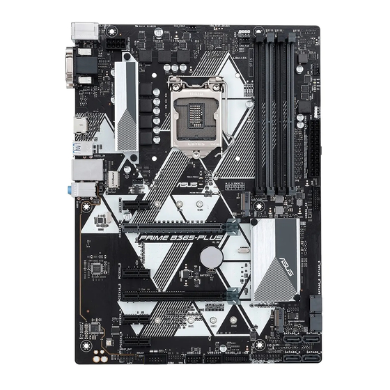
B365 Super PCIEX1_2 PCIEX16_2 M.2_2(SOCKET3) PCIE SATA IRST 22110 2280 2260 2242 PCIEX1_3 128Mb BIOS PCIEX1_4 CLRTC SATA6G_4 SATA6G_3 SPDIF_OUT SATA6G_2 SATA6G_1 USB1112 USB1314 U31G1_12 MONO_OUT AAFP PANEL Unplug the power cord before installing or removing the motherboard. Failure to do so can cause you physical injury and damage motherboard components. ASUS PRIME B365-PLUS... - Page 10 1.2.1 Layout contents Page Connectors/Jumpers/Slots/LED ATX power connectors (24-pin EATXPWR, 8-pin EATX12V) CPU and chassis fan connectors (4-pin CPU_FAN, 4-pin CHA_FAN1~3) Intel LGA1151 CPU socket ® RGB headers (4-pin RGB_HEADER1, RGB_HEADER2) DDR4 DIMM slots USB 3.1 Gen 1 (up to 5Gbps) connectors (20-1 pin U31G1_12, U31G1_56) M.2 Socket 3 Intel B365 Serial ATA 6.0 Gb/s connector (7-pin SATA6G_1~6) ® Clear RTC RAM (2-pin CLRTC) 10. System panel connector (20-3 pin PANEL) 11. USB 2.0 connectors (10-1 pin USB1112, USB1314) 12. TPM connector (14-1 pin TPM) 13. Serial port connector (10-1 pin COM) 14. Mono out header (2-pin MONO_OUT) 15. Front panel audio connector (10-1 pin AAFP) 16. Digital audio connector (4-1 pin SPDIF_OUT) 17. PCI Express 3.0/2.0 x1 slots 18. PCI Express 3.0/2.0 x16 slots ATX power connectors (24-pin EATX12V EATXPWR EATXPWR, 8-pin EATX12V)
- Page 11 +12V G R B no longer than 3m. Before you install or remove any component, ensure that the ATX power 1 2 V supply is switched off or the power cord is detached from the power supply. Failure to do so may cause severe damage to the motherboard, peripherals, or components. • Actual lighting and color will vary with LED strip. • If your LED strip does not light up, check if the RGB LED extension cable and the RGB LED strip is connected in the correct orientation, and the 12V connector is aligned with the 12V header on the motherboard. • The LED strip will only light up when the system is operating. • The LED strips are purchased separately. ASUS PRIME B365-PLUS...
- Page 12 DDR4 DIMM slots Install 2 GB, 4 GB, 8 GB, and 16 GB unbuffered non-ECC DDR4 DIMMs into these DIMM sockets. For more details, refer to System memory. USB 3.1 Gen 1 (up to 5Gbps) connectors (20-1 pin U31G1_56 U31G1_12, U31G1_56) PIN 1 USB3+5V Connect a USB 3.1 Gen 1 module to any of these USB3+5V IntA_P1_SSRX- IntA_P2_SSRX- IntA_P1_SSRX+ connectors for additional USB 3.1 Gen 1 front or rear IntA_P2_SSRX+ IntA_P1_SSTX- IntA_P2_SSTX- IntA_P1_SSTX+ panel ports. These connectors comply with USB 3.1 IntA_P2_SSTX+ IntA_P1_D- Gen 1 specifications and provide faster data transfer IntA_P2_D- IntA_P1_D+ IntA_P2_D+ speeds of up to 5 Gbps, faster charging time for USB- U31G1_12 chargeable devices, optimized power efficiency, and...
- Page 13 • Hard disk drive activity LED (2-pin +HDD_LED-) This 2-pin connector is for the HDD Activity LED. Connect the HDD Activity LED cable to this connector. The HDD LED lights up or flashes when data is read from or written to the HDD. • System warning speaker (4-pin SPEAKER) This 4-pin connector is for the chassis-mounted system warning speaker. The speaker allows you to hear system beeps and warnings. • ATX power button/soft-off button (2-pin PWR_SW) This connector is for the system power button. Pressing the power button turns the system on or puts the system in sleep or soft-off mode depending on the operating system settings. Pressing the power switch for more than four seconds while the system is ON turns the system OFF. ASUS PRIME B365-PLUS...
- Page 14 • Reset button (2-pin RESET) This 2-pin connector is for the chassis-mounted reset button for system reboot without turning off the system power. • Chassis intrusion header (2-pin CHASSIS) This connector is for a chassis-mounted intrusion detection sensor or switch. Connect one end of the chassis intrusion sensor or switch cable to this connector. The chassis intrusion sensor or switch sends a high-level signal to this connector when a chassis component is removed or replaced. The signal is then generated as a chassis intrusion event.
- Page 15 PCI Express 3.0/2.0 x16 slots This motherboard supports two PCI Express 3.0/2.0 x16 graphic cards that comply with the PCI Express specifications. PCI Express operating mode VGA configuration PCIe 3.0 x16_1 (gray) PCIe 3.0 x16_2 x16 (Recommended for single Single VGA/PCIe card VGA card) Dual VGA/PCIe cards • In single VGA card mode, use the PCIe 3.0 x16_1 slot (gray) for a PCI Express x16 graphics card to get better performance. • We recommend that you provide sufficient power when running CrossFireX™ mode. • Connect a chassis fan to the motherboard connector labeled CHA_FAN1/2/3 when using multiple graphics cards for better thermal environment. ASUS PRIME B365-PLUS...
- Page 16 1.2.2 Rear panel connectors PS/2 keyboard/mouse combo port. This port is for a PS/2 mouse or keyboard. Video Graphics Adapter (VGA) port. This 15-pin port is for a VGA monitor or other VGA-compatible devices. LAN (RJ-45) port. This port allows Gigabit connection to a Local Area Network (LAN) through a network hub. Refer to the table below for the LAN port LED indications. LAN port LED indications Speed Activity Link Activity/Link LED Speed LED Status Description Status Description No link 10Mbps connection Orange Linked ORANGE 100Mbps connection Orange (Blinking) Data activity GREEN 1Gbps connection...
- Page 17 — Side Speaker Out To configure a 7.1-channel audio output: Use a chassis with HD audio module in the front panel to support a 7.1-channel audio output. USB 3.1 Gen 1 (up to 5Gbps) ports. These 9-pin Universal Serial Bus (USB) ports connect to USB 3.1 Gen 1 devices. • USB 3.1 Gen 1 devices can only be used for data storage. • Due to the design of the Intel 300 series chipset, all USB devices connected to the ® USB 2.0 and USB 3.1 Gen 1 ports are controlled by the xHCI controller. Some legacy USB devices must update their firmware for better compatibility. • We strongly recommend that you connect USB 3.1 Gen 1 devices to USB 3.1 Gen 1 ports for faster and better performance from your USB 3.1 Gen 1 devices. HDMI port. This port is for a High-Definition Multimedia Interface (HDMI) connector, and is HDCP compliant allowing playback of HD DVD, Blu-ray, and other protected content. DVI-D port. This port is for any DVI-D compatible device. DVI-D can not be converted to output from RGB Signal to CRT and is not compatible with DVI-I. USB 2.0 ports These 4-pin Universal Serial Bus (USB) ports are for USB 2.0/1.1 devices. ASUS PRIME B365-PLUS...
-
Page 18: Central Processing Unit (Cpu)
Core™, Pentium Gold, and ® ® Celeron processors. ® Unplug all power cables before installing the CPU. • Ensure that you install the correct CPU designed for the LGA1151 socket only. DO NOT install a CPU designed for LGA1150, LGA1155 and LGA1156 sockets on the LGA1151 socket. • Upon purchase of the motherboard, ensure that the PnP cap is on the socket and the socket contacts are not bent. Contact your retailer immediately if the PnP cap is missing, or if you see any damage to the PnP cap/socket contacts/motherboard components. • Keep the cap after installing the motherboard. ASUS will process Return Merchandise Authorization (RMA) requests only if the motherboard comes with the cap on the LGA1151 socket. • The product warranty does not cover damage to the socket contacts resulting from incorrect CPU installation/removal, or misplacement/loss/incorrect removal of the PnP cap. Installing the CPU Apply the Thermal Interface Material to the CPU heatsink and CPU before you install the heatsink and fan if necessary. Chapter 1: Product introduction 1-10... -
Page 19: System Memory
• Always install DIMMs with the same CAS latency. For optimal compatibility, we recommend that you install memory modules of the same version or date code (D/C) from the same vendor. Check with the retailer to get the correct memory modules. • DDR4 2666MHz and higher memory modules will run at max. 2666MHz on Intel 8th ® Generation 6-core or higher processors. • Memory modules with memory frequency higher than 2133 MHz and its corresponding timing or the loaded X.M.P. Profile is not the JEDEC memory standard. The stability and compatibility of these memory modules depend on the CPU’s capabilities and other installed devices. • The default memory operation frequency is dependent on its Serial Presence Detect (SPD), which is the standard way of accessing information from a memory module. Under the default state, some memory modules for overclocking may operate at a lower frequency than the vendor-marked value. • For system stability, use a more efficient memory cooling system to support a full memory load (4 DIMMs). • Refer to www.asus.com for the latest Memory QVL (Qualified Vendors List) Recommended memory configurations DIMM_B1 DIMM_B2 DIMM_B2 DIMM_A1 DIMM_A2 DIMM_A2 DIMM_A2 1-11 ASUS PRIME B365-PLUS... - Page 20 Installing a DIMM To remove a DIMM Chapter 1: Product introduction 1-12...
-
Page 21: Chapter 2: Bios Information
Managing and updating your BIOS Save a copy of the original motherboard BIOS file to a USB flash disk in case you need to restore the BIOS in the future. Copy the original motherboard BIOS using the ASUS Update utility. - Page 22 2.1.2 ASUS EZ Flash 3 The ASUS EZ Flash 3 feature allows you to update the BIOS without using an OS‑based utility. • Ensure that you load the BIOS default settings to ensure system compatibility and stability. Select the Load Optimized Defaults item under the Exit menu. See section 2.3 Exit Menu for details.
- Page 23 2.1.3 ASUS CrashFree BIOS 3 utility The ASUS CrashFree BIOS 3 is an auto recovery tool that allows you to restore the BIOS file when it fails or gets corrupted during the updating process. You can restore a corrupted BIOS file using the motherboard support DVD or a USB flash drive that contains the updated BIOS file.
- Page 24 On the BIOS Updater screen, press <Tab> to switch from Files panel to Drives panel then select D:. ASUSTeK BIOS Updater for DOS V1.33 [2014/01/01] Current ROM Update ROM BOARD: PRIME B365-PLUS BOARD: Unknown VER: 0206 (H :00 B :00)
-
Page 25: Bios Setup Program
The BIOS setup screens shown in this section are for reference purposes only, and may not exactly match what you see on your screen. Visit the ASUS website at www.asus.com to download the latest BIOS file for this • motherboard. - Page 26 2.2.1 EZ Mode By default, the EZ Mode screen appears when you enter the BIOS setup program. The EZ Mode provides you an overview of the basic system information, and allows you to select the display language, system performance mode and boot device priority. To access the Advanced Mode, click Advanced Mode or press <F7>...
- Page 27 Language Hot Keys Menu bar Scroll bar Sub-menu item Search on FAQs General help Configuration Last modified fields settings Goes back Menu items to EZ Mode Pop-up window Displays the CPU temperature, CPU and memory voltage output ASUS PRIME B365-PLUS...
- Page 28 Menu bar The menu bar on top of the screen has the following main items: My Favorites For saving the frequently‑used system settings and configuration Main For changing the basic system configuration Ai Tweaker For changing the overclocking settings Advanced For changing the advanced system settings For displaying the system temperature, power status, and changing the Monitor...
- Page 29 Search on FAQ Move your mouse over this button to show a QR code. Scan this QR code with your mobile device to connect to the ASUS BIOS FAQ web page. You can also scan the QR code below. Scroll bar A scroll bar appears on the right side of a menu screen when there are items that do not fit on the screen.
-
Page 30: Exit Menu
Exit menu The Exit menu items allow you to load the optimal default values for the BIOS items, and save or discard your changes to the BIOS items. You can access the EZ Mode from the Exit menu. Load Optimized Defaults This option allows you to load the default values for each of the parameters on the Setup menus. -
Page 31: Appendix
Appendix Notices FCC Compliance Information Responsible Party: Asus Computer International Address: 48720 Kato Rd., Fremont, CA 94538, USA Phone / Fax No: (510)739-3777 / (510)608-4555 This device complies with part 15 of the FCC Rules. Operation is subject to the following two conditions: (1) This device may not cause harmful interference, and (2) this device must accept any interference received, including interference that may cause undesired operation. - Page 32 Compliance Statement of Innovation, Science and Economic Development Canada (ISED) This device complies with Innovation, Science and Economic Development Canada licence exempt RSS standard(s). Operation is subject to the following two conditions: (1) this device may not cause interference, and (2) this device must accept any interference, including interference that may cause undesired operation of the device.
- Page 33 ASUS Recycling/Takeback Services ASUS recycling and takeback programs come from our commitment to the highest standards for protecting our environment. We believe in providing solutions for you to be able to responsibly recycle our products, batteries, other components as well as the packaging materials.
- Page 34 доступний на: www.asus.com/support Cijeli tekst EU izjave o sukladnosti dostupan je na: www.asus.com/support Türkçe AsusTek Computer Inc., bu aygıtın temel gereksinimlerle ve ilişkili Čeština Společnost ASUSTeK Computer Inc. tímto prohlašuje, že toto Yönergelerin diğer ilgili koşullarıyla uyumlu olduğunu beyan eder.
-
Page 35: Asus Contact Information
+1-510-739-3777 +1-510-608-4555 Web site http://www.asus.com/us/ Technical Support Support fax +1-812-284-0883 Telephone +1-812-282-2787 Online support http://qr.asus.com/techserv ASUS COMPUTER GmbH (Germany and Austria) Address Harkort Str. 21-23, 40880 Ratingen, Germany +49-2102-959931 Web site http://www.asus.com/de Online contact http://eu-rma.asus.com/sales Technical Support Telephone +49-2102-5789555 Support Fax...