Table of Contents
Advertisement
Quick Links
Advertisement
Table of Contents

Related Manuals for LG ARUV025GSD0


Summary of Contents for LG ARUV025GSD0
- Page 1 Cooling Only R410A(50/60Hz) 5CVM0-02G(Replaces 5CVM0-02F) P/No. : MFL67474029...
-
Page 2: General Information
General Information 1. Model Names 2. External Appearance 3. Nomenclature... -
Page 3: Model Names
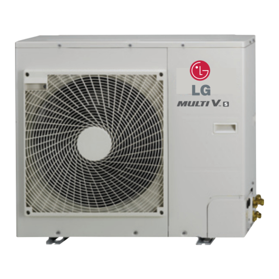
1. Model Names Power Supply 2.5HP 220-240V, 1Ø, 50Hz ARUV025GSD0 ARUV030GSD0 ARUV040GSD0 220V,1Ø, 60Hz 2. External Appearance CHASSIS Model Name Model ARUV025GSD0 ARUV030GSD0 ARUV040GSD0 R410A(50/60Hz) - Page 4 3. Nomenclature Serial Number S : Standard D : Residential Air Discharge Type S : Side Discharge Electrical Ratings G : 1Ø, 220 - 240V, 50Hz / 1Ø, 220V, 60Hz Total Cooling Capacity in Horse Power(HP) unit EX) 8HP → '080' 10HP → '100' Combination of Inverter Type and Cooling Only or Heat Pump N: Inverter and H/P...
-
Page 5: Outdoor Units
Outdoor Units 1. Outdoor Unit Function 2. Specifications 3. Dimensions 4. Electric Characteristics 5. Indoor Unit and Outdoor Unit Capacity Index 6. Capacity Tables 7. Capacity Correction Factor 8. Operation Limits 9. Piping Diagrams 10. Wiring Diagrams 11. Field Wiring 12. - Page 6 PDI(power distribution indicator) PQNUD1S00 PDI(power distribution indicator) Premium PQNUD1S40 Cool / Heat Selector PRDSBM IO Module (ODU Dry Contact) PVDSMN000 LG MV PRCT-FE1 Cycle Monitoring Device Mobile LGMV(Bluetooth) PMVBTQ01 DS(Data Saving) Module PVADTN000 Note : O : Applied, X : Not applied Accessory model name : Installed at field, ordered and purchased separately by the corresponding model name, supplied with separate package.
-
Page 7: Specifications
2. Specifications n Cooling Only 50/60Hz Model Name Combination Unit ARUV025GSD0 ARUV030GSD0 ARUV040GSD0 11.0 Cooling kcal/h 6,191 7,911 9,458 Capacity Btu/h 24,600 31,400 37,600 (Rated) Heating kcal/h Btu/h Cooling 1.80 2.10 2.75 Input (Rated) Heating Power Factor Rated 0.93 0.93 0.93... - Page 8 3. Dimensions 3.1 Dimensional Drawings R410A(50/60Hz)
- Page 9 3. Dimensions R410A(50/60Hz)
-
Page 10: Center Of Gravity
3. Dimensions 3.2 Center of Gravity [Unit : mm] ARUV025GSD0 Model Name ARUV025GSD0 [Unit : mm] ARUV030GSD0 ARUV040GSD0 Model Name ARUV030GSD0 ARUV040GSD0 R410A(50/60Hz) -
Page 11: Electric Characteristics
4. Electric Characteristics u Wiring of Main Power Supply and Equipment Capacity 1. Bear in mind ambient conditions (ambient temperature,direct sunlight, rain liquid,etc.) when proceeding with the wiring and connections. 2. The wire size is the minimum value for metal conduit wiring. The power cord size should be 1 rank thicker taking into account the line voltage drops. - Page 12 4. Electric Characteristics u 50Hz Unit Power Supply COMP Model Volts Voltage-range TOCA RLA(Cooling) RLA(Heating) 2.5 HP 13.4 13.8 0.12 Min.:198, 3 HP 220-240 21.7 21.3 16.4 0.12 Max.:264 4 HP 21.7 21.3 16.3 0.12 u 60Hz Unit Power Supply COMP Model Volts...
- Page 13 5. Indoor Unit and Outdoor Unit Capacity Index 5.1 Outdoor Unit Selection See the indoor unit capacity tables for given Indoor and Outdoor temperature. Select the unit whose capacity is the nearest to or greater than given load. Note: Individual Indoor Unit capacity is subject to change by combination. Actual capacity has to be calculated accord- ing to the combination by using Outdoor unit capacity table.
- Page 14 6. Capacity Tables 6.1 Cooling capacity Cooling Capacity(2.5HP) ARUV025GSD0 Indoor air temp. (DB/WB, °C) Outdoor Combination air temp ℃ DB 0.76 0.93 1.08 1.10 1.12 1.12 10.0 1.13 0.78 0.97 1.13 1.13 1.16 1.17 1.17 0.81 1.00 1.17 1.18 1.20 1.21...
-
Page 15: Capacity Tables
6. Capacity Tables Cooling Capacity(2.5HP) Indoor air temp. (DB/WB, °C) Outdoor Combination air temp ℃ DB 0.56 0.68 0.80 0.87 0.93 1.04 1.05 0.57 0.70 0.83 0.89 0.96 1.09 1.10 0.59 0.73 0.86 0.93 1.00 1.16 1.16 0.61 0.75 0.90 0.97 1.06 1.21... - Page 16 6. Capacity Tables Cooling Capacity(2.5HP) Indoor air temp. (DB/WB, °C) Outdoor Combination air temp ℃ DB 0.41 0.49 0.57 0.61 0.65 0.75 0.83 0.42 0.50 0.58 0.62 0.67 0.76 0.85 0.42 0.50 0.59 0.63 0.68 0.78 0.86 0.43 0.51 0.60 0.64 0.69 0.79...
- Page 17 6. Capacity Tables Cooling Capacity(3HP) ARUV030GSD0 Indoor air temp. (DB/WB, °C) Outdoor Combination air temp ℃ DB 0.89 10.0 1.09 11.6 1.26 12.1 1.29 12.2 1.30 12.5 1.31 12.8 1.32 0.91 10.0 1.13 11.6 1.32 11.9 1.32 12.1 1.35 12.4 1.36 12.7 1.37...
- Page 18 6. Capacity Tables Cooling Capacity(3HP) Indoor air temp. (DB/WB, °C) Outdoor Combination air temp ℃ DB 0.65 0.79 0.94 1.01 1.09 11.0 1.21 12.1 1.22 0.67 0.82 0.97 1.04 1.12 11.0 1.28 11.9 1.29 0.69 0.86 1.01 1.08 1.17 11.0 1.35 11.8 1.36...
- Page 19 6. Capacity Tables Cooling Capacity(3HP) Indoor air temp. (DB/WB, °C) Outdoor Combination air temp ℃ DB 0.48 0.57 0.66 0.71 0.76 0.87 0.97 0.49 0.58 0.68 0.73 0.78 0.88 0.99 0.50 0.58 0.69 0.74 0.79 0.91 1.01 0.50 0.60 0.70 0.75 0.81 0.92...
- Page 20 6. Capacity Tables Cooling Capacity(4P) ARUV040GSD0 Indoor air temp. (DB/WB, °C) Outdoor Combination air temp ℃ DB 10.1 1.17 12.0 1.42 13.9 1.65 14.4 1.69 14.6 1.70 15.0 1.71 15.3 1.72 10.1 1.20 12.0 1.48 13.9 1.72 14.2 1.73 14.5 1.76 14.8 1.78...
- Page 21 6. Capacity Tables Cooling Capacity(4P) Indoor air temp. (DB/WB, °C) Outdoor Combination air temp ℃ DB 0.85 1.03 10.3 1.23 11.0 1.33 11.7 1.42 13.2 1.58 14.4 1.60 0.88 1.07 10.3 1.27 11.0 1.36 11.7 1.47 13.2 1.67 14.2 1.69 0.91 1.12 10.3...
- Page 22 6. Capacity Tables Cooling Capacity(4P) Indoor air temp. (DB/WB, °C) Outdoor Combination air temp ℃ DB 0.63 0.75 0.87 0.93 1.00 1.14 10.2 1.27 0.64 0.76 0.89 0.95 1.02 1.16 10.2 1.30 0.65 0.77 0.90 0.97 1.04 1.19 10.2 1.32 0.66 0.78 0.92...
-
Page 23: Capacity Correction Factor
7. Capacity Correction Factor 7.1 2.5/3/4 HP Rate of change in Cooling capacity 0.98 0.96 0.94 0.92 0.90 α 10 - 0.99 0.97 0.93 0.91 0.90 7.5 - 0.99 0.97 0.93 0.91 0.90 1.00 0.97 0.93 0.91 0.90 L(m) L(m) L(m) 0.97 0.93... - Page 24 7. Capacity Correction Factor Notes 1. These figures illustrate the rate of change in capacity of a standard indoor unit system at maximum load under standard conditions.(Moreover, under partial load conditions there is only a minor deviation from the rate of change in capacity shown in the above figures.) 2.
-
Page 25: Operation Limits
8. Operation Limits Cooling 50°C 48°C 40°C 35°C 30°C 25°C 20°C 15°C 10°C 5°C 0°C -5°C 10°C 14°C 15°C 20°C 25°C 27°C 30°C Indoor Temperature(°C WB) Notes: These figures assume the following operating conditions: Equivalent piping length:7.5m Level difference:0m 20 _ R410A(50/60Hz) -
Page 26: Piping Diagrams
9. Piping Diagrams 9.1 2.5 HP Cooling Operation / Oil Return Indoor Heat Exchanger Indoor Heat Exchanger Electronic Electronic Flare Flare Expansion Valve Expansion Valve Joint Joint Flare Flare Joint Joint High Temperature High Pressure Gas High Temperature High Pressure Liquid Low Temperature Low Pressure Gas Outdoor Temperature... - Page 27 9. Piping Diagrams 9.2 3 / 4HP Cooling Operation / Oil Return Indoor Heat Exchanger Indoor Heat Exchanger Electronic Electronic Flare Flare Expansion Valve Expansion Valve Joint Joint Flare Flare Joint Joint High Temperature High Pressure Gas High Temperature High Pressure Liquid Low Temperature Low Pressure Gas Outdoor Temperature...
-
Page 28: Wiring Diagrams
10. Wiring Diagrams 10.1 2.5 HP _ 23 R410A(50/60Hz) - Page 29 10. Wiring Diagrams 10.2 3 / 4 HP 24 _ R410A(50/60Hz)
- Page 30 11. Field Wiring 11.1 50/60Hz u Example Connection of Communication Cable n Single Outdoor Unit Voltage range(V) Frequency Outdoor Indoor 50Hz 220-240V 220-240V Power supply Swich 60Hz 220V 220V Power supply (1-phase 2-wire) (Main Switch) Power cable (2-wire Cable) Communication cable(3-wire Cable) Communication cable (2-wire Cable) Pull Box 1.5mm...
-
Page 31: Field Wiring
11. Field Wiring u Example Connection of Communication Cable [BUS type] [STAR type] • Connection of communication cable must be installed • Abnormal operation can be caused by communication like below figure between indoor unit to outdoor unit. defect, when connection of communication cable is installed like below figure(STAR type). - Page 32 Unit : dB(A) Sound Pressure Levels (60Hz) Model Cooling Heating ARUV025GSD0 ARUV030GSD0 ARUV040GSD0 Notes: • Data is valid at free field condition • Data is valid at nominal operating condition • Sound level will vary depending on a range of factors...
- Page 33 Installation of Outdoor Units 1. Alternative Refrigerant R410A 2. Select the Best Location 3. Installation Space 4. Lifting Method 5. Installation 6. Refrigerant piping Installation 7. Refrigerant piping system 8. Electrical Wiring...
-
Page 34: Select The Best Location
1. Alternative Refrigerant R410A • The refrigerant R410A has the property of higher operating pressure in comparison with R22. Therefore, all materials have the characteristics of higher resisting pressure than R22 ones and this characteristic should be also considered during the installation. R410A is an azeotrope of R32 and R125 mixed at 50:50, so the ozone depletion potential (ODP) of R410A is 0. - Page 35 2. Select the Best Location 3. When installing the outdoor unit in a place that is constantly exposed to a strong wind like a coast or on a high story of a building, secure a normal fan operation by using a duct or a wind shield. •...
-
Page 36: Installation Space
3. Installation Space • The following values are the least space for installation. If any service area is needed for service according to field circumstance, obtain enough service space. • The unit of values is mm. 3.1 Individual Installation n In case of obstacles on the suction side 1. - Page 37 3. Installation Space n In case of obstacles on the discharge side [Unit:mm] 1. Stand alone installation 2. Collective installation n In case of obstacles on the suction and the discharge side Ú Obstacle height of discharge side is higher than the unit 1.
- Page 38 3. Installation Space 2. Collective installation L > H L > H Ú Obstacle height of discharge side is lower than the unit 1. Stand alone installation [Unit:mm] L ≤ H L ≤ H 2. Collective installation L ≤ H L ≤...
-
Page 39: Seasonal Wind And Cautions In Winter
3. Installation Space 3.2 Collective / continuous installation Space required for collective installation and continuous installation: When installing several units, leave space between each block as shown below considering passage for air and people. 1. One row of stand alone installation [Unit:mm] 2. - Page 40 Wind speed : Vs ≤ 1.5 m/s Secure minimum intake area When the intake area is not secured can efficiency drop and products may not be operating • Minimum intake area (For reference) ARUV025GSD0 Model ARUV030GSD0 ARUV040GSD0 Minimum intake area (m...
-
Page 41: Lifting Method
4. Lifting Method • When carrying the suspended, unit pass the ropes between legs of base panel under the unit. • Always lift the unit with ropes attached at four points so that impact is not applied to the unit. •... -
Page 42: Installation
• Anchor bolts must be inserted at least 75mm. For outdoor units should not be supported only by the corner supports. Center of the Unit Center of the Unit 5.1 The location of the Anchor bolts [Unit : mm] ARUV025GSD0 ARUV030GSD0 ARUV040GSD0 1,090 R410A(50/60Hz) - Page 43 5. Installation 5.2 Foundation for Installation • Fix the unit tightly with bolts as shown below so that unit will not fall down due to earthquake or gust. • Use the H-beam support as a base support • Noise and vibration may occur from the floor or wall since vibration is transferred through the installation part depending on installation status.
-
Page 44: Refrigerant Piping Installation
6. Refrigerant piping Installation 6.1 Precautions on Pipe connection / Valve operation Pipe connection is done by connecting from the end of the pipe to the branching pipes, and the refrigerant pipe coming out of the out- door unit is divided at the end to connect to each indoor unit. Flare connection for the indoor unit, and welding connection for the out- door pipe and the branching parts. -
Page 45: Selection Of Refrigerant Piping
7. Refrigerant Piping System 7.1 Pipe Connection Method between outdoor unit / indoor unit 7.1.1 Selection of Refrigerant Piping Outdoor unit Gas pipe Liquid pipe Branching pipe Main pipe Indoor unit Branching pipe Piping parts Name Selection of pipe size Size of main pipe Liquid pipe Gas pipe... - Page 46 7. Refrigerant Piping System 7.2 Refrigerant piping system Y branch method Example : 5 Indoor Units connected Ⓐ : Outdoor Unit Ⓑ : 1st branch (Y branch) Ⓒ : Indoor Units Outdoor unit capacity (HP) Total pipe length (m) A+B+C+D+a+b+c+d+e Longest pipe length (m) (Equivalent pipe length) A+B+C+D+e Longest pipe length after 1st branch (m)
- Page 47 7. Refrigerant Piping System Header Method Example : 6 Indoor Units connected Ⓐ : Outdoor Unit Ⓑ : 1st branch Ⓒ : Indoor Units Ⓓ : Sealed piping Outdoor unit capacity (HP) Total pipe length (m) A+a+b+c+d+e+f Longest pipe length (m) (Equivalent pipe length) Longest pipe length after 1st branch (m) Difference in height (m) (Outdoor Unit ÷...
- Page 48 7. Refrigerant Piping System Combination of Y branch/header method Example : 5 Indoor Units connected Ⓐ : Outdoor Unit Ⓑ : 1st branch (Y branch) Ⓒ : Y branch Ⓓ : Indoor Unit Ⓔ : Header Ⓕ : Sealed piping Branch pipe can not be used after header Outdoor unit capacity (HP) Total pipe length (m)
- Page 49 7. Refrigerant Piping System Refrigerant pipe diameter from outdoor unit to first branch. (A) Outdoor unit total capacity (HP) Liquid pipe [mm(inch)] Gas pipe [mm(inch)] Ø9.52(3/8) Ø15.88(5/8) Ø9.52(3/8) Ø15.88(5/8) Ø9.52(3/8) Ø15.88(5/8) Refrigerant pipe diameter from branch to branch (B,C) Downward Indoor Unit Liquid pipe [mm(inch)] Gas pipe [mm(inch)] total capacity [kW(Btu/h)]...
- Page 50 7. Refrigerant Piping System 7.2 Indoor Unit Connection Ú Indoor Unit connecting pipe from branch (a,b,c,d,e,f) Indoor Unit capacity Liquid pipe [mm(inch)] Gas pipe [mm(inch)] [kW(Btu/h)] ≤ 5.6(19,100) Ø6.35(1/4) Ø12.7(1/2) < 16.0(54,600) Ø9.52(3/8) Ø15.88(5/8) ≤ 22.4(76,400) Ø9.52(3/8) Ø19.05(3/4) ≤ 28.0(95,900) Ø9.52(3/8) Ø22.2(7/8) CAUTION...
-
Page 51: Distribution Method
7. Refrigerant Piping System 7.4 Distribution Method 1. Line Distribution 3rd main pipe distribution Main pipe Distribution 3rd main pipe distribution 2. Vertical Distribution Ensure that the branch pipes are attached vertically. 3. The others Header 18 _ R410A(50/60Hz) - Page 52 7. Refrigerant Piping System 7.5 Selection of Y Branch and Header 7.5.1 Y Branch [unit:mm] Models Gas pipe Liquid pipe I.D12.7 I.D12.7 I.D6.35 I.D15.88 I.D15.88 I.D.6.35 I.D9.52 I.D9.52 I.D15.88 ARBLN01621 I.D.6.35 I.D12.7 I.D.9.52 O.D15.88 O.D9.52 I.D12.7 I.D19.05 I.D22.2 I.D19.05 I.D15.88 I.D19.05 I.D12.7 I.D12.7...
- Page 53 7. Refrigerant Piping System 7.5.2 Header [unit:mm] Models Gas pipe Liquid pipe ID6.35 ID12.7 ID6.35 ID12.7 4 branch ID9.52 ID15.88 ID9.52 ARBL054 ID15.88 ID12.7 ID9.52 ID15.88 ID19.05 ID6.35 ID12.7 7 branch ID12.7 ID9.52 ID15.88 120 150 ARBL057 ID15.88 ID9.52 ID15.88 ID12.7 ID19.05 ID15.88...
-
Page 54: Electrical Wiring
8. Electrical Wiring 8.1 Electrical Wiring 8.1.1 Caution 1) Follow ordinance of your governmental organization for technical standard related to electrical equipment, wiring regulations and guidance of each electric power company. WARNING Be sure to have authorized electrical engineers do the electric work using special circuits in accordance with regulations and this installation manual. - Page 55 8. Electrical Wiring CAUTION • This product have reversed phase protection detector that only works when the power is turned on. If there exists black out or the power goes on and off which the product is operating, attach a reversed phase protection circuit locally.
-
Page 56: Communication And Power Cables
8. Electrical Wiring 8.1.2 Communication and Power Cables 1) Communication cable - Types : shielding cable - Cross section : 1.0~1.5mm - Maximum allowable temperature: 60°C - Maximum allowable cable length: under 300m 2) Remote control cable • Types : 3-core cable 3) Central control cable Product type Cable type... - Page 57 8. Electrical Wiring 8.2 Checking the setting of outdoor units 8.2.1 Checking according to dip switch setting - You can check the setting values of the Master outdoor unit from the 7 segment LED. The dip switch setting should be changed when the power is OFF. 8.2.2 Checking the initial display The number is sequentially appeared at the 7 segment in 5 seconds after applying the power.
- Page 58 8. Electrical Wiring 8.3 Automatic Addressing • The address of indoor units would be set by auto addressing 1) Wait for 3 minutes after supplying power. (IDU and ODU should be off) 2) Press RED button of the outdoor units for 5 seconds. (5/6HP : SW01, 2.5/3/4HP : SW02) 3) A “88”...
- Page 59 8. Electrical Wiring u The Procedure of Automatic Addressing Power On Waiting 3 minutes Press RED Button for 5 sec. (SW01C) Auto addressing start 7-segment LED = 88 Don’t press RED Button (SW01C) • When auto addressing has completed, number of indoor unit Waiting about 2~7 minutes connected to outdoor unit will be displayed on 7 segment LED for 30 seconds...
- Page 60 Special Guide 1. Cautions for Refrigerant Leaks 2. Installation guide at the seaside...
-
Page 61: Caution For Refrigerant Leaks
1. Caution For Refrigerant Leaks The installer and system specialist shall secure safety against leakage according to local regulations or standards. The following standards may be applicable if local regulations are not available. 1.1 Introduction Though the R410A refrigerant is harmless and incombustible itself , the room to equip the air conditioner should be large enough to such an extent that the refrigerant gas will not exceed the limiting concentration even if the refrigerant gas leaks in the room. - Page 62 1. Caution For Refrigerant Leaks (3) With partition and without opening which serve as passage of air to adjoining room Outdoor unit Indoor unit Smallest room n Calculate refrigerant concentration Total amount of replenished In case the result of calculation exceeds refrigerant in refrigerant facility (kg) ≤...
- Page 63 2. Installation guide at the seaside CAUTION 1. Air conditioners should not be installed in areas where corrosive gases, such as acid or alkaline gas, are pro- duced. 2. Do not install the product where it could be exposed to sea wind (salty wind) directly. It can result corrosion on the product.
-
Page 64: Installation And Maintenance
2. Installation guide at the seaside 2.2 Installation and maintenance Even though the corrosion resistance model has reinforced material or coating, it is still not completely safe from corro- sion. And for this reason, you need to increase the effect of preventing corrosion through installation planning and mainte- nance/repair. - Page 65 Yeongdeungpo-gu, Seoul, Korea (07336) http://partner.lge.com Copyright © 2014-2021 LG Electronics The air conditioners manufactured by LG have received ISO9001 certificate for quality assurance Inc. All Rights Reserved. and ISO14001 certificate for environmental management system. Printed in Korea March / 2021...