Table of Contents
Advertisement
Quick Links
TopPage
In the interests of user-safety the oven should be restored to its original condition and only parts identical to those
specified should be used.
CHAPTER 1. BEFORE SERVICING
CHAPTER 2. WARNING TO SERVICE PERSONNEL
CHAPTER 3. PRODUCT DESCRIPTION
CHAPTER 4. OPERATION
CHAPTER 5. TROUBLESHOOTING GUIDE
CHAPTER 6. TEST PROCEDURES
CHAPTER 7. TOUCH CONTROL PANEL ASSEMBLY
CHAPTER 8. PRECAUTIONS FOR USING LEAD-
SERVICE MANUAL
MICROWAVE OVEN
MODELS
CONTENTS
FREE SOLDER
CHAPTER 9. COMPONENT REPLACEMENT AND
ADJUSTMENT PROCEDURE
CHAPTER 10. MICROWAVE MEASUREMENT
CHAPTER 11. TEST DATA AT A GLANCE
CHAPTER 12. CIRCUIT DIAGRAMS
Parts List
S5902R210ATPH
COMMERCIAL
R-1500AT
R-2100AT
This document has been published to be used for
after sales service only.
The contents are subject to change without notice.
R1500AT
Advertisement
Table of Contents

Related Manuals for Sharp R-1500AT


Summary of Contents for Sharp R-1500AT
- Page 1 TopPage R1500AT SERVICE MANUAL S5902R210ATPH COMMERCIAL MICROWAVE OVEN R-1500AT MODELS R-2100AT In the interests of user-safety the oven should be restored to its original condition and only parts identical to those specified should be used. CONTENTS CHAPTER 1. BEFORE SERVICING FREE SOLDER CHAPTER 2.
-
Page 2: Table Of Contents
CONTENTS CHAPTER 1. BEFORE SERVICING CHAPTER 8. PRECAUTIONS FOR USING LEAD- GENERAL IMPORTANT INFORMA- FREE SOLDER TION ............1-1 WARNING........... 1-1 CHAPTER 9. COMPONENT REPLACEMENT AND CAUTION MICROWAVE RADIATION ..1-2 ADJUSTMENT PROCEDURE WARNINGS ..........9-1 CHAPTER 2. -
Page 3: Chapter 1. Before Servicing
[1] GENERAL IMPORTANT INFORMATION This Manual has been prepared to provide Sharp Corp. Service engineers with Operation and Service Information. It is recommended that service engineers carefully study the entire text of this manual, so they will be qualified to render satisfactory customer ser- vice. -
Page 4: Caution Microwave Radiation
R1500AT [3] CAUTION MICROWAVE RADIATION Personnel should not be exposed to the microwave energy which may radiate from the magnetron or other microwave generating devices if it is improperly used or connected. All input and output microwave connections, waveguides, flanges and gaskets must be secured. -
Page 5: Chapter 2. Warning To Service Personnel
Indien het water nog steeds schroevedraaier kortsluit tegen het chassis. koud is, herhaalt u de allereerste drie stappen en controleer Sharp beveelt ten sterkste aan dat, voor zover mogelijk, nogmaals de aansluitingen naar de geteste onderdelen. defecten worden opgespoord wanneer de stekker uit het Wanneer alle reparaties zijn uitgevoerd en de oven weer in stopcontact is gehaald. - Page 6 R1500AT 2 – 2...
- Page 7 R1500AT 2 – 3...
-
Page 8: Chapter 3. Product Description
R1500AT PRODUCT DESCRIPTION Service Manual [1] SPECIFICATIONS ITEM DESCRIPTION Power Requirements Single phase 230V, 50Hz, 3 wire earthed R-1500AT 2.3kW Power Consumption R-2100AT 3.0kW R-1500AT 1500W Operating frequency 2450 MHz (IEC60705) Power Output R-2100AT 2100W Operating frequency 2450 MHz (IEC60705) -
Page 9: Installation Information
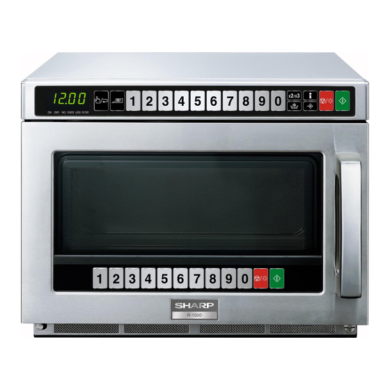
R1500AT 2. TOUCH CONTROL PANEL DOOR SIDE 7. Ten number pads 1. MANUAL/REPEAT pad 4. CUSTOM SETTING pad 8. EXPRESS DEFROST pad 2. POWER LEVEL pad 5. STOP/CLEAR pad 9. SET MEMORY pad 3. DOUBLE/TRIPLE QUANTITY pad 6. START pad [3] INSTALLATION INFORMATION When this commercial microwave oven is installed near other commercial electrical appliances, connect a lead wire to each equivalent potential ter- minal with equipotential marking between them (insert a lead wire between a washer and an earth angle, and screw them), as shown in Fig. -
Page 10: Chapter 4. Operation
R1500AT CHAPTER 4. R1500AT OPERATION Service Manual [1] DESCRIPTION OF OPERATING SEQUENCE The following is a description of component functions during oven operation. 1. OFF CONDITION 8. The monitor switch SW3 is electrically monitoring the operation of the secondary interlock switch SW1 and primary interlock relay 1. -
Page 11: Description And Function Of Components
R1500AT [2] DESCRIPTION AND FUNCTION OF COMPONENTS 1. DOOR OPEN MECHANISM 2. As the door goes to a closed position, the contacts of the monitor switches SW3, SW4 are opened first, then the contacts of the door 1. The handle lever is pulled. sensing switch SW5 and the secondary interlock switches SW1, 2. - Page 12 R1500AT 10. FAN MOTORS: FM 1. The high voltage rectifier is shorted by some fault when microwave cooking or dual cooking. The fan motors drive blades which draw external cool air into the oven. 2. The peak reverse voltage of D2 of the rectifier goes beyond the This cool air is directed through the air vanes surrounding the magne- rated peak reverse voltage 1.7 KV in the voltage doubler circuit.
-
Page 13: Chapter 5. Troubleshooting Guide
R1500AT CHAPTER 5. R1500AT TROUBLESHOOTING GUIDE Service Manual Never touch any part in the circuit with your hand or an uninsulated tool while the power supply is connected. When troubleshooting the microwave oven, it is helpful to follow the Sequence of Operation in performing the checks. Many of the possible causes of trouble will require that a specific test be performed. - Page 14 R1500AT SPECIFICATION OF ERROR Outline Operation when error occurs Display in operation usually When a basic performance and the function are ruined Displaying and heating stop EE0, EE1, EE2, EE3, EE8 When the dangers of the state of the high temperature and the ignition, etc. are Displaying and heating stop foreseen When you mistake the setting of the heating time...
-
Page 15: Chapter 6. Test Procedures
Room temperature (T0) ......around 20°C Initial temperature (T1) ........10±1°C Water load ............1000 g Mass of container (mc) ........330 g Heating time ....28 sec. [R-1500AT]/ 20 sec. [R-2100AT] P = 150 x T [R-1500AT] P = 210 x T [R-2100AT] T2 ............ -
Page 16: B: Power Transformer Test
T" (for R-2100AT)....P = 210 x 10°C = 2100 Watts JUDGEMENT: The measured output power should be at least ± 15% of the rated output power. CAUTION: 1°C CORRESPONDS TO 150WATTS (for R-1500AT)/ 210WATTS (for R-2100AT). REPEAT MEASUREMENT IF THE POWER IS INSUF- FICIENT. -
Page 17: D: High Voltage Capacitor (C1) And/Or (C2) Test
R1500AT 3. CARRY OUT 4R CHECKS. NOTE: Be sure to use an ohmmeter that will supply a forward bias voltage of more than 6.3 volts. [4] D: HIGH VOLTAGE CAPACITOR (C1) AND/OR (C2) TEST 1. CARRY OUT 3D CHECKS. 2. If the capacitor is open, no high voltage will be available to the magnetron. Disconnect input leads and check for short or open between the termi- nals using an ohmmeter. -
Page 18: I: Weak Point
R1500AT [8] H: WEAK POINT F1, F2 TEST 1. CARRY OUT 3D CHECKS. 2. If the weak point F1 or F2 is blown when the door is opened, check the primary interlock relay RY1, secondary interlock switches SW1, SW2 and monitor switches SW3, SW4 according to the “TEST PROCEDURE”... -
Page 19: N: Noise Filter Test
R1500AT [14] N: NOISE FILTER TEST 1. CARRY OUT 3D CHECKS. Source Source (Blue) (Brown) NOISE FILTER 2. Disconnect the lead wires from the terminal the noise filter. Using an ohmmeter, check DISCHARGE RESISTOR between the terminals as described in the following table. If incorrect reading are obtained, 470K 1/2W replace the noise filter. -
Page 20: Q: Power Unit Test
R1500AT 1. In connection with pads. 1) When touching the pads, a certain group of pads do not produce a signal. 2) When touching the pads, no pads produce a signal. 2. In connection with display 1) At a certain digit, all or some segments do not light up. 2) At a certain digit, brightness is low. -
Page 21: S: Antenna Sensor Test
R1500AT [19] S: ANTENNA SENSOR TEST There is no test procedure for the antenna sensor. When the error history display shows EE15, EE25 or EE35, if the antenna motors, control unit and wiring are normal, the antenna sensor may be defective. -
Page 22: Special Function For Servicing
R1500AT CHAPTER 7. R1500AT TOUCH CONTROL PANEL ASSEMBLY Service Manual [1] SPECIAL FUNCTION FOR SERVICING This oven has the special functions for servicing as shown in the table 1 ~ 4. By using the special function, service person can check the using time or the using number of times for the electrical parts. Also service person can check the AC supply voltage and /or set the standard voltage. - Page 23 R1500AT For example: Procedure to check the total cooking number of times (example, 957700 times) and using time (example, 1260 hours) of MG 1 and set 0 hours after MG1 is replaced. : no sound : 0.1 second sound : 2.0 second sound : (0.06 sec.
- Page 24 R1500AT 2. Error history (SF-4) For example: Procedure to check current voltage (In case of under 230V) You can check the most recent 10 error histories. Operation Display Indicator Sound For example: Procedure to check the error histories that have been memorized in memory 1, memory 2 and memory 9.
- Page 25 R1500AT 4. Exhaust thermistor check (SF-6) You can check if the exhaust thermistor works correctly or not by using this function. For example: In case the exhaust thermistor works correctly (275ml water load is necessary.), the display will show “OH” as follows. Operation Display Indicator...
- Page 26 R1500AT 5. Set of standard voltage (SF-7) When the control unit or the relay unit is replaced, set the standard voltage, referring to following procedure. Because the control unit judges if the AC supply voltage is 240V+10% or 230V-12% by comparing with the standard voltage. The temporary standard voltage is set when the oven is shipped from the factory.
- Page 27 (within 20 sec.) POWER LEVEL SET MEMORY (within 20 sec.) START STOP/CLEAR CUSTOM cXXH (model name) (date) XXXX (time) XXXX STOP/CLEAR #1: The display will show “c21H” or “c15H”. “c21H” means model R-2100AT. “c15H” means model R-1500AT. 7 – 6...
-
Page 28: Servicing For Brinted Wiring Boards
R1500AT [2] SERVICING FOR BRINTED WIRING BOARDS 1. Precautions for Handling Electronic Components b) On some models, the power supply cord between the printed wiring boards and the oven proper is long enough that they This unit uses CMOS LSI in the integral part of the circuits. When han- may be separated from each other. -
Page 29: Chapter 8. Precautions For Using Lead
R1500AT CHAPTER 8. R1500AT PRECAUTIONS FOR USING LEAD-FREE SOLDER Service Manual Employing lead-free solder The “Main PWB” of this model employs lead-free solder. This is indicated by the “LF” symbol printed on the PWB and in the service manual. The suffix letter indicates the alloy type of the solder. -
Page 30: Chapter 9. Component Replacement And Adjustment Procedure Warnings
4. If the outer case (cabinet) is not fitted. WARNING FOR WIRING To prevent an electric shock, take the following precau- Oven cavity. tions. 3) Sharp edge: 1. Before wiring, Bottom plate, Oven cavity, Waveguide flange Chassis 1) Disconnect the power supply cord. support and other metallic plate. -
Page 31: Power Transformers (1) And/Or (2) Removal
R1500AT 10.Remove the six (6) screws holding the rear cover and exhaust 12.Now, the rear cover with the fan motor and exhaust cover is free. cover to the bottom plate, power supply cord angle, intake duct and NOTE: Do not forget to re-connect the wire leads to the exhaust fan exhaust duct. -
Page 32: Power Supply Cord Replacement
R1500AT 6. Remove the capacitor band from the high voltage capacitor. 2) DO NOT REPLACE ONLY THE HIGH VOLTAGE REC- TIFIER. IF IT IS DEFECTIVE, REPLACE THE HIGH 7. Disconnect all wire leads from the high voltage capacitor. VOLTAGE RECTIFIER ASSEMBLY. 8. -
Page 33: Fan Motors Removal
R1500AT [10] FAN MOTORS REMOVAL 1. CARRY OUT 3D CHECKS. 2. Remove the rear cover. 5. Release the wire leads of the fan motor from the wire holder. 3. Disconnect the connector of the fan motor from the connector of 6. -
Page 34: Door Sensing Switch (Sw5)/Secondary Interlock Switches (Sw1, Sw2) And Monitor Switches (Sw3, Sw4) Replacement
R1500AT NOTE: When the relay unit is replaced, set the standard voltage refer- ring to Special Function pages. [15] DOOR SENSING SWITCH (SW5)/SECONDARY INTERLOCK SWITCHES (SW1, SW2) AND MONITOR SWITCHES (SW3, SW4) REPLACEMENT 1. REMOVAL Mount the door sensing switch in the lower position of latch hook. MONITOR SWITCHES 1. -
Page 35: Door Disassembly
R1500AT 5. Release upper and lower hinges and the hinge cover from door 2. Deviation of the door alignment from horizontal line of cavity face assembly. plate is to be less than 1.0mm. 6. Now, door assembly is free. 3. The door is positioned with its face depressed toward the cavity face plate. - Page 36 R1500AT 3. KEY UNIT (IN DOOR ASSEMBLY) REMOVAL 7. UPPER AND LOWER LATCH HEADS REMOVAL After removing door panel; After removing door panel; 1. Remove the five (5) screws holding the key fixing plate to the door 1. Remove the latch spring from the latch angle assembly and the frame.
-
Page 37: Oven Lamp And Lamp Socket Removal
R1500AT [19] OVEN LAMP AND LAMP SOCKET REMOVAL 1. CARRY OUT 3D CHECKS. Oven lamp 2. Remove the oven lamp. socket 3. By pushing the tab, remove the lamp spacer with the lamp socket from the lamp angle assembly. Terminal 4. -
Page 38: Chapter 10. Microwave Measurement
R1500AT CHAPTER 10. R1500AT MICROWAVE MEASUREMENT Service Manual After adjustment of door latch switches, monitor switch and door are completed individually or collectively, the following leakage test must be per- formed with a survey instrument and it must be confirmed that the result meets the requirements of the performance standard for microwave oven. REQUIREMENT The safety switch must prevent microwave radiation emission in excess of 5mW/cm at any point 5cm or more from external surface of the oven. - Page 39 Magnetron thermistor (Upper) Approx. 750kΩ at the room temperature Magnetron thermistor (Lower) Approx. 750kΩ at the room temperature Oven lamp 240V 25W High voltage capacitor for R-1500AT C1, C2 0.82μF AC 2300V High voltage capacitor for R-2100AT C1, C2 1.13μF AC 2300V...
-
Page 40: Oven Schematic
SENSOR (2) SW2: SECONDARY INTERLOCK SWITCH CAPACITOR R-2100AT : 1.13uF NEUTRAL R-1500AT : 0.82uF Figure O-1a Oven Schematic-OFF condition right after the oven is plugged in. SCHEMATIC NOTE: CONDITION OF OVEN 4. DOOR OPENED. 5. “0” APPEAR ON DISPLAY. POWER... - Page 41 SENSOR (2) SW2: SECONDARY INTERLOCK SWITCH CAPACITOR R-2100AT : 1.13uF NEUTRAL R-1500AT : 0.82uF Figure O-1c Oven Schematic-OFF condition after the oven door is closed. SCHEMATIC NOTE: CONDITION OF OVEN 1. DOOR CLOSED. 2. MANUAL/ REPEAT PAD TOUCHED. 3. COOKING TIME PROGRAMMED.
- Page 42 R1500AT [2] Figure S-1. Pictorial Diagram TF1: Magnetron temp.fuse (1) White High voltage capacitor (2) Wire holder MG1: Magnetron Magnetron thermistor (1) White CPU harness Blue High voltage (Blue case) capacitor (1) Red (Red case) Magnetron thermistor (2) Crosstape MG2: Magnetron Gray Power transformer Crosstape...
- Page 43 R1500AT High voltage High voltage rectifier (1) capacitor (1) Magnetron SW4: Monitor switch Asymmetric rectifier (1) Power transformer (1) SW3: High voltage Monitor Blue (Blue case) capacitor (2) switch White (Blue case) SW2: Brown Secondary interlock Gray High voltage rectifier (2) switch Main wire Gray/Red...
- Page 44 R1500AT NOTE: The red and blue wire leads to the cabinet side terminals of Main wire harness RY2 and RY3 should go through inside the core of CT1 3 WHT Cook relay (1) Main wire Cook relay (2) harness Primary interlock relay RY1 Main wire harness DC harness 12...
- Page 45 R1500AT [3] Figure S-2. Switching Power Supply Unit Circuit 12 – 6...
- Page 46 R1500AT [4] Figure S-3. Relay Unit Circuit NOTE: IF NOT SPECIFIED : 1/4W J% : 1SS133 RTRNPA162DR : NOT INSERT PARTS CN-D 1N4002x4 : CHECK POINT D292 D291 VRS1 S10K300 D294 D293 CN-A V-SENS D-12 GND-1 O.L. PCJ-124D3M CN-E 24V-2 24V 2 24V-1 SW POWER...
- Page 47 R1500AT [5] Figure S-4. Control Unit/ Antenna sensor/ Microwave Sensor Circuit 12 – 8...
- Page 48 R1500AT [6] Figure S-5. Printed Wiring Board CONTROL UNIT ANTENNA SENSOR SWITCH UNIT RELAY UNIT MICROWAVE SENSOR SWITCHING POWER SUPPLY UNIT 12 – 9...
-
Page 49: Parts List
INSTRUCTION BOOK BOTTOM PAD ASSEMBLY TOUCH GUIDE FPADBA692WRKZ CAUTION SHEET Not replaceable parts PACKING CASE FPAK-A607WRKZ [R-2100AT] FPAK-A608WRKZ [R-1500AT] This document has been published to be used for after sales service only. The contents are subject to change without notice. - Page 50 R1500AT [1] OVEN PARTS 7-21 4-64 7-31 4-74 4-63 4-48 4-34 4-12 7-21 7-21 7-25 2-2-1 7-28 6-14 7-13 4-10 4-63 7-21 7-21 4-48 7-28 4-60 Vinyl insulation tape: 7-21 7-21 20mm (W) x 520mm (L) 7-28 Please get the vinyl insulation 2-10 tape from a local vender 7-21...
- Page 51 Fuse Holder 1-10 High Voltage Rectifier assembly FH-DZA145WRZZ Antenna Motor RMOTDA238WRZZ High Voltage Capacitor [R-2100AT] RC-QZA315WRZZ RC-QZA363WRZZ High Voltage Capacitor [R-1500AT] High Voltage Capacitor [R-2100AT] RC-QZA315WRZZ High Voltage Capacitor [R-1500AT] RC-QZA363WRZZ Exhaust Fan Motor (DC24V) RMOT-A037WRZZ Exhaust Motor assembly (DC24V) FMOT-A031WRKZ...
- Page 52 R1500AT PRICE PART PARTS CODE DESCRIPTION RANK MARK RANK [1] OVEN PARTS 4-32 Antenna Cover GCOVPA027WRPZ 4-33 Antenna Cover Knob JKNBKA800WRFZ 4-34 Support Angle LANGKB292WRPZ 4-35 Lamp Angle assembly FANGQA180WRYZ 4-36 Capacitor Unit Angle LANGQA752WRPZ 4-37 LANGQA702WRPZ Motor Fixing Angle 4-38 Face Support Angle LSUB-A137WRPZ...
- Page 53 R1500AT [2] DOOR AND CONTROL PANEL PARTS 3-12 3-12 3-10 3-11 5-34 5-20 5-17 5-28 5-18 5-3-2 5-34 5-18 5-3-1 5-17 5-19 5-21 5-33 5-14 5-30 5-25 5-26 5-31 5-29 5-11 5-27 5-32 5-10 5-13 5-24 5-16 5-15 5-12 5-16 5-11 5-35 5-32...
- Page 54 PCUSGA737WRPZ 5-19 Harness Cushion PCUSGA738WRPZ 5-20 Pipe PPIPPA017WRFZ 5-21 Key Protect Cover PSHEPB325WREZ 5-24 Door Badge [R-2100AT] HBDGCA135WRRZ 5-24 Door Badge [R-1500AT] HBDGCA136WRRZ 5-25 Earth Spring MSPRCA174WREZ 5-26 DPWB-A569DRKZ Switch Unit 5-27 Key Unit FUNTKB197WREZ 5-28 Door Key harnes FW-VZC153WREZ...
- Page 55 R1500AT INDEX PRICE PART PRICE PART PARTS CODE PARTS CODE RANK MARK RANK RANK MARK RANK LHLDWA011WRE0 2-6-12 [ C ] LHLDWA013WRE0 2-6-3 CDORFB149WRKZ LHLDWA063WREZ 1-6-11 [ D ] LRTNPA001DRZZ 2-5-30 DDAI-A217WRKZ 1-2-1 LRTNPA002DRZZ 2-5-31 DDUC-A071WRKZ 1-4-2 LSTPPA261WRFZ 2-5-5 DDUC-A072WRKZ 1-4-17 LSTPPA288WRMZ 2-5-11...
- Page 56 R1500AT PRICE PART PARTS CODE RANK MARK RANK PSHEGA011WREZ 1-2-6 PSHEPB323WREZ 1-4-69 PSHEPB325WREZ 2-5-21 PSHEPB332WREZ 2-3-10 PSHEPB353WREZ 1-4-29 PSHEPB455WREZ 1-4-74 PSKR-A462WRPZ 1-4-47 PSKR-A464WRPZ 1-4-55 PSKR-A500WRPZ 1-4-73 PSPASA027WRFZ 1-4-72 [ Q ] QFS-CA024WRE0 1-F1 " 1-F2 QFSHDA019WRE0 1-1-9 QFS-TA014WRE0 1-TF1 " 1-TF2 QFS-TA015WRE0 1-TF3...