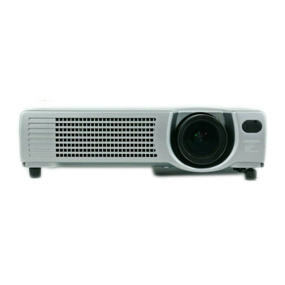
Hitachi CPS317 Service Manual
Hide thumbs
Also See for CPS317:
- User manual (43 pages) ,
- User manual (54 pages) ,
- User manual (53 pages)
Table of Contents
Advertisement
Quick Links
SERVICE MANUAL
Be sure to read this manual before servicing. To assure safety from fire, electric shock, injury, harmful
radiation and materials, various measures are provided in this Hitachi Multimedia LCD Projector. Be sure
to read cautionary items described in the manual to maintain safety before servicing.
1. When replacing the lamp, avoid burns to your fingers. The lamp becomes very hot.
2. Never touch the lamp bulb with a finger or anything else. Never drop it or give it a shock. They may cause
bursting of the bulb.
3. This projector is provided with a high voltage circuit for the lamp. Do not touch the electric parts of power
unit (main), when turning on the projector.
4. Do not touch the exhaust fan, during operation.
5. The LCD module assembly is likely to be damaged. If replacing the LCD module assembly, do not hold
the FPC of the LCD module assembly.
6. Use the cables which are included with the projector or specified
1. Features --------------------------------------------------- 2
2. Specifi cations--------------------------------------------- 2
3. Names of each part ------------------------------------ 5
4. Adjustment ------------------------------------------------ 7
5. Troubleshooting ---------------------------------------- 13
6. Service points ------------------------------------------ 18
7. Block diagram ------------------------------------------ 30
SPECIFICATIONS AND PARTS ARE SUBJECT TO CHANGE FOR IMPROVEMENT.
Multimedia LCD Projector
Caution
Service Warning
Contents
January 2003 Digital Media Division
SM0524
CPS317(C3S3)
CPX327(C3XM3)
EDS3170(C3S3)
EDX3270(C3XM3)
EDS3170A(C3S3E)
EDX3270A(C3XM3)
ED-X3250AT(C3X3ET)
EDX3280AT(C3XM4ET)
8. Connector connection diagram -------------------- 32
9. Wiring diagram ----------------------------------------- 34
10.Basic circuit diagrams------------------------------- 40
11.Disassembly diagram --------------------------------- 59
12.Replacement parts list-------------------------------- 61
13.RS-232C communication ---------------------------- 64
Advertisement
Table of Contents

Related Manuals for Hitachi CPS317


Summary of Contents for Hitachi CPS317
-
Page 1: Table Of Contents
Be sure to read this manual before servicing. To assure safety from fire, electric shock, injury, harmful radiation and materials, various measures are provided in this Hitachi Multimedia LCD Projector. Be sure to read cautionary items described in the manual to maintain safety before servicing. -
Page 2: Features
CPS317, EDS3170, EDS3170A, CPX327, EDX3270, EDX3270A 1. Features 1,500 ANSI lumens, 2.7kg(6lbs) Full connectivity Easy and flexible keystone adjustment My screen Wide angle lens Low noise 2. Specifications CPS317/EDS3170 /EDS3170A CPX327/EDX3270/EDX3270A Drive system TFT active matrix Liquid crystal Panel size 0.7 inches... - Page 3 EDX3280AT, EDX3250AT Features EDX3280AT, (1,200 lumens, 2.7kg(6lbs) EDX3250AT) Specification /EDX3250AT...
- Page 4 EDX3280AT Difference with the conventional model The base model of EDX3280AT is EDX3270A. The liquid crystal panel is the main change from EDX3270A. The main differences with the base model are described in the following table.
- Page 5 ED-X3250AT (C3X3E-T) Difference with the conventional model The base model of ED-X3250AT is ED-X3270A. The liquid crystal panel is mainly changed from ED-X3270A. The main differences with the base model are described in the following table. The main differences with the conventional model Difference Contents Note...
-
Page 6: Names Of Each Part
3. Names of each part Parts names RESET button MENU button KEYSTONE button POWER LED TEMP LED INPUT button LAMP LED STANDBY/ON button Zoom ring Focus ring Air filter Elevator button Remote sensor S-VIDEO IN port AUDIO IN R and L ports VIDEO IN port RGB IN 1 and 2 ports AC power inlet... - Page 7 SEARCH button STANDBY/ON button RGB button STANDBY/ON VIDEO SEARCH AUTO button VIDEO button ASPECT AUTO BLANK ASPECT button BLANK button MAGNIFY HOME PAGE UP VOLUME VOLUME button MAGNIFY button PAGE DOWN MUTE MUTE button FREEZE KEYSTONE FREEZE button KEYSTONE button KEYBOARD buttons POSITION MENU...
-
Page 8: Adjustment
R color ghost is at a minimum. (Set the adjustment value to default, and then raise the value. When a ghost appears to the left of a vertical line, reduce the value by 2 steps. :CPS317/EDS3170 only) 0/255 112/255 2. - Page 9 3. In the same way, use DAC-P - V.COM-G: in the Adjustment menu to adjust the G color flicker. 4. In the same way, use DAC-P - V.COM-B: in the Adjustment menu to adjust the B color flicker. CPS317/EDS3170/EDS3170A 4-4 PSIG-G adjustment (vertical stripe adjustment) Signals for internal adjustment Adjustment procedure 1.
- Page 10 CPX327/EDX3270/EDX3270A 4-4 NRSH adjustment (vertical stripe adjustment) Signals for internal adjustment Adjustment procedure 1. Make this adjustment after completing the adjustment in 4-3 Flicker adjustment. 2. Use DAC-P - NRSH - R: in the Adjustment menu to adjust so that the vertical lines spaced every 6 dots are as inconspicuous as possible.
- Page 11 4-6 Color uniformity adjustment Preparations 1. Perform these adjustments after the white balance 6. To temporarily turn correction off, place the cursor adjustment described in Section 4-5. on “ON” in the Adjust Tone menu and press the [ ] 2. Make a color uniformity adjustment for the key.
- Page 12 Adjustment procedure 1 (when a color differential meter is used) 1. First adjust [MID-L] tone [G:]. 9. Similarly, measure adjustment points [No.3] to [No.17] and adjust their color coordinates starting 2. Select adjustment point [No.2][G:]. When the background is not [G] monochrome, in order from the small number points.
- Page 13 Adjustment procedure 2 (visual inspection) 1. First adjust [MIN] tone [G:]. 6. View measurement points [No.2], [No.3], 2. Select [No.2] [G:]. [No.10] and [No.11]. Adjust the [R] and [B] of If the background is [G] monochrome, press the each measurement point so that they have the [MENU SELECT] key on the Remote control same color as measurement point [No.1].
-
Page 14: Troubleshooting
5. Troubleshooting Check points at trouble shooting TH950 PWB assembly SENSOR E302 E800 E805 E807 I256 PWB assembly Drive CHJ17 TP118 TP1H TP106 TP117 TP105 TP110 TP103 TP102 TP116 TP104 TP114 TP115 TEMPERATURE E101 SENSOR IS01 PWB assembly Signal... - Page 15 Power can not be turned on voltage input Disconnect at pins TSW form Power unit Open E800 on the PWB assembly (circuit). And check Drive at standby TSW short or mode? open? : +14V : +17V Short : +6V : +4.3V Fuse Power unit (circuit) on Power unit (circuit)
- Page 16 Lamp does not light What is the state of Light Light Change the lamp. Lamp LAMP indicator Does lamp light? during operation? Not light Not light Is the voltage at the of E805 on the PWB PWB assembly Drive assembly Drive fixed to "L" during warming-up? "L"...
- Page 17 Picture is not displayed only when the RGB signal is input Check at operating mode signal input Change the IS01 on the at each pin of E101 on PWB assembly Signal. PWB assembly Signal the PWB assembly It is repaired ? Drive? (TP06) : R signal...
- Page 18 No sound Check at operating mode Are the signals input at each pin of E101 on the PWB assembly Drive? PWB assembly Drive (TP117) : MUTE (0V) (TP104) : CLK-VOLUME Control (TP115) : DATA-VOLUME Control (TP118) : POWER-AUDIO (+3.3V) PWB assembly Signal Power unit (circuit) Speaker Can not operate to Mouse...
-
Page 19: Service Points
6. Service points Lead free solder [CAUTION] This product uses lead free solder (unleaded) to help preserve the environment. Please read these instructions before attempting any soldering work. Caution: Always wear safety glasses to prevent fumes or molten solder from getting into the eyes. Lead free solder can splatter at high temperatures (600˚C). - Page 20 6. Service points Cautions when removing the PWB assembly Drive When removing the PWB assembly Drive, there is danger of damaging the connector connecting cables and the PWB assembly Signal. 1) Disconnect 6 cables and remove 3 screws. PWB assembly Drive Disconnect 6 cables Remove 3 screws 2) Lift up the rearward of the PWB assembly Drive to the front.
- Page 21 Therefore, regarding these parts, you can either replace part , LCD / Lens Prism assembly, or send the whole unit LCD / Lens Prism assembly back to Hitachi, where we will replace the malfunctioning part, recondition the device and send it back to you.
- Page 22 • To reset the air filter timer, from the OPTION menu, select FILTER TIME. (Select RESET on the menu with the button.) Lamp ( Option Lamp: DT00511(CPS317/EDS3170/EDS3170A) / DT00521(CPX327/EDX3270/EDX3270A) HIGH VOLTAGE HIGH TEMPERATURE HIGH PRESSURE Before replacing the lamp, check the serial number of the replacement lamp bulb (sold separately: DT00511 for CPS317/EDS3170/EDS3170A or DT00521 for CPX327/EDX3270/EDX3270A), then contact your local dealer.
- Page 23 45 minutes, and prepare a new lamp (sold • Also steadily push the opposite side of the separately: DT00511 for CPS317/EPS3170/EPS3170A screwed side of the lamp into the unit. or / DT00521 for CPX327/EDX3270/EDX3270A)
- Page 24 Resetting the Lamp Timer Reset the lamp timer after replacing the lamp. When the lamp has been replaced after the LAMP indicator is red, or the CHANGE THE LAMP message is displayed, complete the following operation within ten minutes of switching power ON.
- Page 25 Notice of AUTO adjustment Use of AUTO adjustment with the image through RGB input optimizes VPOSI, HPOSI, HSIZE and HPHASE automatically. In case that projected image has dark tone around its peripheral, AUTO operation sometimes makes artifacts in the image, shifts capture area and so on. Those failures are caused by period of image data is not exactly distinguished to period of blanking on signal processing.
- Page 26 PIN BOX (ID Inquiring Code) 2. Send HITACHI sales company the Inquiring code (10 digits) to inquire the correct PIN code. 3. With the PIN BOX menu displayed, input the correct PIN code. Enter the correct PIN CODE that HITACHI sales company informed.
- Page 27 Related Messages When the unit's power is ON, messages such as those shown below may be displayed. When any such message is displayed on the screen, please respond as described below. Message Description CHANGE THE LAMP Lamp usage time is approaching 2,000 hours. (Note 2) Preparation of a new lamp, and an early lamp change, is AFTER REPLACING LAMP, recommended.
- Page 28 Regarding the Indicator Lamps Lighting and flashing of the POWER indicator, the LAMP indicator, and the TEMP indicator have the meanings as described in the Table below. Please respond in accordance with the instructions within the Table. POWER LAMP TEMP Description indicator indicator...
- Page 29 SERVICE MENU To display the OSD for “SERVICE MENU” set up. By the control panel By the remote control transmitter SERVICE yellow(selected item) 1. Display the menu by the 1. Display the menu by the FANSPEED “MENU” button. “MENU” button. B-SPEED DURABLE MODE 2.
- Page 30 Setup of Filter time (“ON” or “OFF”) 1. Select the “FILTER TIME” on the OSD using button “ ” by the SERVICE MENU. SERVICE yellow(selected item) same as the menu color FANSPEED white(not selected item) B-SPEED DURABLE MODE VIDEO NR LENS MUTE COLOR FILTER TIME...
- Page 31 DRIVE PWB INPUT PWB RGB OUT EEPROM 1M SRAM Flash ROM 1st_PLL A/D, PLL RGB IN1 CXA3506R PANEL CPS317/EDS3170 : SVGA RGB IN2 CPX327/EDX3270 : XGA L3E6070 L3E7050B CLAMP or L3E6090 COLOR SYNC Component SEPARATOR UNIFORMITY Video 0.7" LCD &...
-
Page 32: Block Diagram
DRIVE PWB INPUT PWB RGB OUT A/D,���� PANEL ED-S3170A�SVGA 1st_PLL CXA3506R ED-X3270A�XGA EEPROM 1M SRAM Flash ROM RGB�IN1 � ONLY ED-X3270A ��� CLAMP RGB�IN2 L3E7050B L3E6070 orL3E6090 G-Port COLOR Video VIDEO UNIFORMITY DECODER 0.7"LCD S-Video & VPC3230Q �L3E1040 V-Port PANEL PW265-10T TIMING LEVEL... -
Page 33: Connector Connection Diagram
8. Connector connection diagram (C3S3, C3XM3) 70P B-B 24/30P PFC(Flat) CONNECTOR With Panel(OPT Unit) 1: B 70: B Y IN 2: GND(B) 69: GND(B) SVGA 3: G 68: G (CP-S317) (CP-X327) 4: GND(G) 67: GND(G) 1:COM 1:NC 5: R 66: R 2:VVDD 2:DY Pb/Cb IN... - Page 34 Connector connection diagram (C3S3E, C3XM3E) �������� ����������������� ���������� ��������������������� ������ ������ ��������� ����������� ����������� ���� ��� ������ ������ ����������� ����������� ����������� ����������� ������� ����� ������ ������ �������� ����� ����������� ����������� ����������� ������� ������ ���������� ���������� ������� ������� ���������� ���������� ������� �������...
- Page 35 Wiring for Circuit Power Supply and Ballast Power Supply Boards Wiring for Circuit Power Supply Board Wiring for Ballast Power Supply Board (1) Keep a record of the circuit power supply lot number in the 100% inspection record. (1) Keep a record of the ballast power supply lot number in the 100% inspection record. (2) Connect the TSW.
- Page 36 Wiring for Power Supply (for Board Sub-assembling) Lamp lead During power supply assembling (1) Wire and connect the CNPWR. (2) Lay the lamp leads. TAP6 (3) Apply the TAP6. (4) Hook the CNTH lead and apply the TAP10. Apply the TAP6 to the specified position on the lamp leads shown in the illustration.
- Page 37 Before installing the optical unit, put all of leads away from where the Wiring for Bottom Case Assembling optical unit is installed as illustrated below so no lead can become entangled. During bottom case assembling CNTH CNPOW (1) Connect the CNSP to the A83. CNBAR (2) Take care not to entangle any lead when installing the optical unit.
- Page 38 Pass the CNRM through the specified position as illustrated and avoid passing it between the boss and the lens barrel Wiring for Optical Unit Installation (to prevent the lens from contacting the cable). During optical unit installation Boss (1) Connect the CNRM. (2) Apply the TAP1.
- Page 39 Wiring before Drive Board Installation Before drive board installation (1) Wire the CNBAR. (2) Wire and install the TSW. (3) Lay and fix the lamp leads. (4) Lay the #3020 lead. (5) Wire the TSW. (6) Apply the TAP7. CNTH CNPOW CNBAR Do not loosen the TSW cable (to keep the cable...
- Page 40 Wiring for Drive Board Installation E800 E302 Procedure (1) Before installing the drive board, connect the CNBAR and the #6222 while CNBAR holding the drive board with your hand. (2) Put the drive board in the position where you install it then connect the CNTH, the CNPOW, the #6220 and the #6221 while lifting the rear of the board.
-
Page 41: Basic Circuit Diagrams
10. Basic circuit diagram Parts with hatching are not mounted. PWB assembly SENSOR (C3S3/C3XM3) PWB assembly SWITCH (C3S3/C3XM3) PWB assembly REMOTE (C3S3/C3XM3) - Page 42 POWER UNIT (BALLAST) (C3S3/C3XM3)
- Page 43 POWER UNIT (CIRCUIT)(C3S3/C3XM3)
- Page 44 PWB assembly DRIVE 1 (C3S3/C3XM3) 43 1...
- Page 45 PWB assembly DRIVE 2 (C3S3/C3XM3)
- Page 46 PWB assembly DRIVE 3 (C3S3/C3XM3)
- Page 47 PWB assembly DRIVE 4 (C3S3/C3XM3)
- Page 48 PWB assembly DRIVE 5 (C3S3/C3XM3)
- Page 49 PWB assembly DRIVE 6 (C3S3/C3XM3)
- Page 50 PWB assembly DRIVE 7 (C3S3/C3XM3)
- Page 51 PWB assembly DRIVE 8 (C3S3/C3XM3)
- Page 52 PWB assembly DRIVE 9 (C3S3/C3XM3)
- Page 53 PWB assembly DRIVE 10 (C3S3/C3XM3)
- Page 54 PWB assembly SIGNAL 1 (C3S3/C3XM3)
- Page 55 PWB assembly SIGNAL 2 (C3S3/C3XM3)
- Page 56 PWB assembly SIGNAL 3 (C3S3/C3XM3)
- Page 57 PWB assembly INPUT 1 (C3S3E/C3XM3E)
- Page 58 PWB assembly INPUT 2 (C3S3E/C3XM3E)
- Page 59 PWB assembly INPUT 3 (C3S3E/C3XM3E)
-
Page 60: Disassembly Diagram
11. Disassembly diagram M : Meter screw T : Tapping screw M3X8 T3X12 T3X12 M3X10 M3X10 M3X8 DT M3X8 DT... - Page 61 M : Meter screw M3X10 T : Tapping screw M3X10 M3X10 M3X8 M3X8 M3X8 M3X10 T3X12 T3X12 T3X12 T3X12 M3X8 T2X5 M3X8 DT M3X8 M3X8 DT...
- Page 62 THE UPDATED PARTS LIST FOR THIS MODEL IS AVAILABLE ON ESTA...
-
Page 63: Rs-232C Communication
13. RS-232C communication (1) Turn off the projector and computer power supplies and connect with the RS-232C cable. (2) Turn on the computer power supply and after the computer has started up, turn on the projector power supply. Projector Computer RS-232C jack D-sub 9-pin Control jack... - Page 64 ����������������������������������������� ���������������������������������������������������������������������������� ������������������������������������������������� ���������������������������������������������������������������������������������� ��������������������������������������������� ������������������������������������������������������������������������������ ����������������������������������������������������������� ���������������������������������������������������������������������� ������������������������������������������������������������������ ���������������������������������������������������� ����������������������������������������������������������������������������������� ���������������������������������������������� ��������������������������������������������������������������������� ������������������������������������������������������������������ ���������������������������������������������������������� ������������������������������������������������������������������������������ ���������������������������������������������� ������������������������������������������������������������������������� ������������������������������������������������������������������ ���������������������������������������������������������� ����������������������������������������������������������������������������� ������������������������������������������������ ������������������������������������������������������������������������ ������������������������������������������������������������������ ������������������������������������������������ ��������������������������������������������������������������������������������������� ������������������������������������������ ������������������������������������������������������������������������������������������ ������������������������������������������������������������������������������������������� ����������������������������������������������������������������������������������������� ��������������������������������������������� ������������������������������������������������������������������������������������ ��������������������������������������������������� ��������������������������������������������������������������������������������������� �������������������������������������������������������������������������������������� ����������������������������������������������������������������������������������������� �������������������������������������������������������������������������� � ���� ������������������������������������������������������������� ��������������������������...
- Page 65 Command data chart Command data Names Operation type Header Action Type Setting code Blue BE EF 06 00 CB D3 01 00 00 30 03 00 White BE EF 06 00 6B D0 01 00 00 30 05 00 Black BE EF 06 00 9B D0...
- Page 66 Command data chart Command data Names Operation type Header Action Type Setting code H.Position Reset Execute BE EF 06 00 IC D3 06 00 03 70 00 00 H.Size Reset Execute BE EF 06 00 68 D2 06 00 04 70 00 00 Color Balance Execute...
- Page 67 Command data chart Command data Names Operation type Header Action Type Setting code BE EF 06 00 FD D3 02 00 04 20 00 00 Contrast Increment BE EF 06 00 9B D3 04 00 04 20 00 00 Decrement BE EF 06 00 4A D2...
- Page 68 Command data chart Command data Names Operation type Header Action Type Setting code BE EF 06 00 49 73 02 00 03 22 00 00 Tint Increment BE EF 06 00 2F 73 04 00 03 22 00 00 Decrement BE EF 06 00 FE 72...
- Page 69 Fax: +46 (0) 8 562 711 13 Email: csgswe@hitachi-eu.com Tel: +39 02 38073415 Servizio Clienti Fax: +39 02 48786381/2 Email: customerservice.italy@hitachi-eu.com HITACHI EUROPE S.A.S HITACHI EUROPE LTD (Norway) AB Lyon Office STRANDVEIEN 18 B.P. 45, 69671 BRON CEDEX 1366 Lysaker FRANCE...