Toshiba TS3000 Series Instruction Manual
Hide thumbs
Also See for TS3000 Series:
- Instruction manual (368 pages) ,
- Communications manual (174 pages) ,
- Instruction manual (107 pages)
Table of Contents
Advertisement
Quick Links
TS3100 SCARA / LINEAR / 6-AXIS system
• Make sure that this instruction manual is delivered to the
final user of Toshiba Machine's industrial robot.
• Before operating the industrial robot, read through and
completely understand this manual.
• After reading through this manual, keep it nearby for future
reference.
INSTRUCTION MANUAL
INTERFACE MANUAL
TOSHIBA MACHINE CO., LTD.
NUMAZU, JAPAN
Notice
STE 80729-1
Advertisement
Table of Contents

Related Manuals for Toshiba TS3000 Series


Summary of Contents for Toshiba TS3000 Series
- Page 1 INTERFACE MANUAL Notice • Make sure that this instruction manual is delivered to the final user of Toshiba Machine's industrial robot. • Before operating the industrial robot, read through and completely understand this manual. • After reading through this manual, keep it nearby for future reference.
- Page 2 INTERFACE MANUAL Copyright 2008 by Toshiba Machine Co., Ltd. All rights reserved. No part of this document may be reproduced in any form without obtaining prior written permission from Toshiba Machine Co., Ltd. The information contained in this manual is subject to change without prior notice to effect improvements.
- Page 3 INTERFACE MANUAL Preface This manual describes the type, function and handling method of external cables connecting the TS3100 robot controller with an external equipment. This manual is intended for the system designers and manufacturing engineers. The TS3100 robot controller can work in concert with the external equipment through digital input and output signals that can be programmed by the SCOL language.
- Page 4 INTERFACE MANUAL Cautions on Safety This manual contains the important information on the robot and controller to prevent injury to the operators and persons nearby, to prevent damages to assets and to assure correct use. Make sure that you well understand the following details (indications and symbols) before reading this manual.
- Page 5 INTERFACE MANUAL To perform the work ranging from robot installation to operation with safety, read through and through the Safety CAUTION Manual provided separately before actually starting the work. STE 80729 – 5 –...
- Page 6 Otherwise, the performance will deteriorate, resulting in troubles. Disassembly Prohibited • To replace parts, use the spare parts designated by Toshiba Machine. • Carry out the maintenance and inspection on a regular basis. Mandatory Otherwise, the equipment may go wrong or accidents will be caused.
-
Page 7: Table Of Contents
INTERFACE MANUAL Table of Contents Page Type of External Cable ..................10 Layout and Name of Connectors ..............10 TS3100 Power Cable "ACIN" "POWER" ............. 11 Robot Control Cables.................. 11 1.3.1 TS3100 Motor Drive Cable "MOTOR" ..........11 1.3.2 TS3100 Encoder Cable "ENC" ............11 1.3.3 Robot Control Signal Cable "HAND".......... - Page 8 INTERFACE MANUAL Connecting Robot Control Signal Cable............21 3.3.1 Connecting Robot Control Signal Cable (SCARA Type Robot) ..21 3.3.2 Connecting Robot Control Signal Cable (6-axis Robot)....23 Connecting External I/O Signal Cable..............27 Connecting External Input Signal Cable (INPUT)........27 Connecting External Output Signal Cable (OUTPUT).........
- Page 9 INTERFACE MANUAL Connecting Trigger Input Signal Cable (TRIG) ............ 108 Fabricating Trigger Input Signal Cable............109 Attaching and Detaching Trigger Input Signal Cable......... 109 10. Connecting Conveyor Synchronization Signal Cable (CONV) ......110 10.1 Fabricating Incremental Encoder Input Signal Cable ........ 111 10.2 Attaching and Detaching Incremental Encoder Input Signal Cables ..
-
Page 10: Type Of External Cable
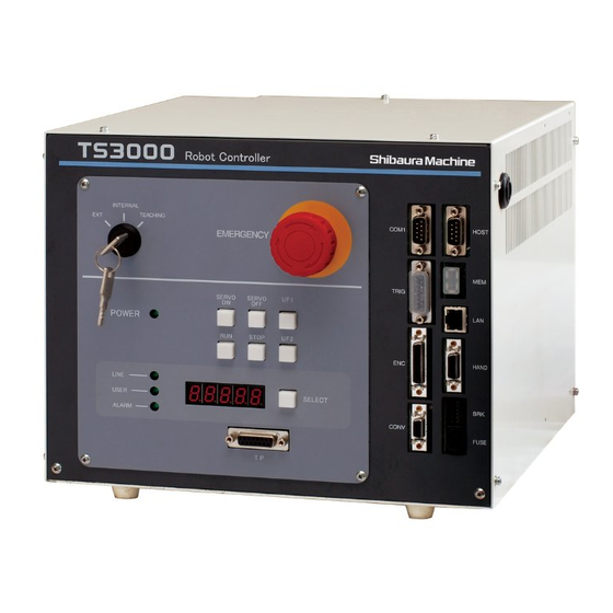
INTERFACE MANUAL Type of External Cable Layout and Name of Connectors The TS3100 robot controller is connected with the robot and external equipment, using connectors and terminal block provided on the front and rear sides of the controller. Fig. 1 Layout and name of connectors STE 80729 –... -
Page 11: Ts3100 Power Cable "Acin" "Power
INTERFACE MANUAL TS3100 Power Cable "ACIN" "POWER" Fig.1-[1], [3] (with connector) TS2000:The power cable is an interface feeding the main power (single phase, 200–240 VAC, 50/60 Hz) to the TS3100 robot controller. Connector "ACIN" is used. Switch “POWER” is used. For details, see the Installation &... -
Page 12: Robot Control Signal Cable "Brk
INTERFACE MANUAL 1.3.4 Robot Control Signal Cable "BRK" Fig. 1-[12] (with cable) This cable is used to turn on and off the parking brake for securing the robot motor shaft. Connector "BRK" is used. External I/O Signal Cables 1.4.1 Power Supply for I/O and Safe Input Cable “EMS” Fig. -
Page 13: Serial I/O Signal Cable
INTERFACE MANUAL 1.4.2 and external output signal in Para. 1.4.3, allow the robot controller to work in concert with the external equipment. Serial I/O Signal Cable 1.5.1 Serial I/O Signal "COM1" Fig. 1-[4] Of the serial input and output signals of three (3) channels equipped on the TS3100 robot controller, the D-SUB 9-pin connector located on the first line of the front connector unit in Fig. -
Page 14: Trigger Cable "Trig
INTERFACE MANUAL Trigger Cable "TRIG" Fig. 1-[6] The standard controller includes eight (8) trigger function inputs. This is used for data latch, conveyor synchronization, and other functions. Connector "TRIG" is used, which is the D-sub 15-pin connector located on the top section of the front panel. -
Page 15: Fieldbus Cable "Fieldbus" (Option)
INTERFACE MANUAL 1.11 Fieldbus Cable "FieldBUS" (Option) Fig. 1-[16] The Fieldbus slave module supports three Fieldbus types: Profibus, DeviceNet, and CC-LINK. "FieldBUS" is located in the top section of the rear panel in Fig. 1. 1.12 Teach Pendant Cable "TP" Fig. -
Page 16: Connecting Power Cable
INTERFACE MANUAL Connecting Power Cable To connect the power cable, use the attached connector (JL04V–6A22–22SE-EB-R; made by Japan Aviation Electronics Industry). AC IN User side Robot controller Single phase 200-240 VAC 50/60 Hz (±1 Hz) Grounding (Class D grounding) JL04V-2E22-22PE-B Connector: JL04V-6A22-22SE-EB-R Clamp: JL04-2022CK (14)-R Fig. -
Page 17: Connecting Robot Control Cable
INTERFACE MANUAL Connecting Robot Control Cable Connecting Motor Drive Cable 3.1.1 Connecting Motor Drive Cable (SCARA Type Robot) To connect the motors, use the attached cables. Motor drive Connector Connector TS3100 cable MOTOR MOTOR Robot robot controller Axis 1 Axis 2 Axis 3 Axis 4 Fig. -
Page 18: Connecting Motor Drive Cable (6-Axis Robot)
INTERFACE MANUAL 3.1.2 Connecting Motor Drive Cable (6-axis Robot) To connect the motors, use the attached cables. Motor drive Connector Connector cable MOTOR CN21 TS3100 robot controller Robot U- A V - A Axis 1 W- A U- B V - B Axis 2 W- B Axis 3... -
Page 19: Connecting Encoder Cable
INTERFACE MANUAL Connecting Encoder Cable 3.2.1 Connecting Encoder Cable (SCARA Type Robot) To connect the encoders to the TS3100 digital servo printed board (X8GL), use the attached cables. Connector Connector TS3100 Encoder cable robot controller Robot ARQ/SD 1RQ/SD 1RQ/SD * ARQ/ SD* Axis 1 encode... -
Page 20: Connecting Encoder Cable (6-Axis Robot)
INTERFACE MANUAL 3.2.2 Connecting Encoder Cable (6-axis Robot) To connect the encoder to the TS3100 digital servo printed board (X8GL), use the attached cables. Connector Connector Encoder cable TS3100 CN20 robot controller Robot J 1BS ARQ/ SD 1RQ/ SD ARQ/ SD * 1RQ/ SD * Axis 1 encoder... -
Page 21: Connecting Robot Control Signal Cable
INTERFACE MANUAL Connecting Robot Control Signal Cable 3.3.1 Connecting Robot Control Signal Cable (SCARA Type Robot) To connect the robot control signal cable, use the attached cables. The I/O common comes in the two (2) types; Type N [X8GN (output sink type) is selected for the I/O printed board and the polarity is the same as in the SR7000 robot] and Type P [X8GI (output source type) is selected for the I/O printed board). - Page 22 INTERFACE MANUAL [Type P] (When X8GI printed board is used) HAND TS3100 Robot control signal cable Robot robot controller ( ): Signal name of DIN (X8GC printed board) command (201) (202) (203) (204) (205) P24G (206) Sink type (“-” common) (207) (208) ( ): Signal name of DOUT...
-
Page 23: Connecting Robot Control Signal Cable (6-Axis Robot)
INTERFACE MANUAL 3.3.2 Connecting Robot Control Signal Cable (6-axis Robot) [Type N] (When X8GN printed board is used) HAND CN20 Robot control signal cable TS3100 Robot robot controller ( ): Signal name of DIN (X8GC printed board) command (201) (202) (203) (204) (205) - Page 24 INTERFACE MANUAL [Type P] (When X8GI printed board is used) HAND CN20 TS3100 Robot control signal cable Robot robot controller ( ): Signal name of DIN command (X8GC printed board) (201) (202) (203) (204) (205) P24G Sink type (“-” common) (206) (207) (208)
- Page 25 INTERFACE MANUAL All of the hand output signals are turned off when the controller power has turned on or turned off. When designing the end effector, therefore, take careful precautions not to drop a part at power failure, etc. The robot control signal can be controlled from the robot language program. In the robot language, the robot control signal is specified by the signal name assigned to each signal.
- Page 26 INTERFACE MANUAL CAUTION If the current which exceeds the rated output current is supplied, the output device may be damaged or the printed board may be burnt. To avoid this, be sure to use within the rated output current. For further information on the robot control signal cable connection, see the Installation &...
-
Page 27: Connecting External I/O Signal Cable
I/O printed board]. After confirming the type of your controller, connect the external input signal cables. This connector is not included in the accessories. Therefore, please order one separately from Toshiba Machine or obtain one yourself. STE 80729 – 27 –... - Page 28 INTERFACE MANUAL [Type N] (When X8GN printed board is used) INPUT TS3100 User side robot controller ( ): Signal name of DIN (X8GN printed board) command DIN1 DIN2 P24V DIN3 DIN4 DIN5 DIN6 DIN7 DIN8 DIN9 Source type (“+” common) DIN10 (10) DIN11...
- Page 29 INTERFACE MANUAL [Type P] (When X8GI printed board is used) INPUT TS3100 User side ( ): Signal name of DIN robot controller command (X8GI printed board) DIN1 DIN2 DIN3 DIN4 DIN5 DIN6 DIN7 DIN8 P24G DIN9 Sink type DIN10 (10) (“-”...
-
Page 30: Connecting External Output Signal Cable (Output)
I/O printed board]. After confirming the type of your controller, connect the external output signal cables. This connector is not included in the accessories. Therefore, please order one separately from Toshiba Machine or obtain one yourself. STE 80729 – 30 –... - Page 31 INTERFACE MANUAL [Type N] (When X8GN printed board is used) OUTPUT TS3100 ( ):Signal name of DOUT User side robot controller command (X8GN printed board) DOUT1 DOUT2 DOUT3 DOUT4 DOUT5 DOUT6 DOUT7 DOUT8 Digital output signals DOUT9 DOUT10 (10) P24G DOUT11 (11) Sink type...
- Page 32 INTERFACE MANUAL [Type P] (When X8GI printed board is used) OUTPUT TS3100 User side ( ):Signal name of DOUT robot controller command (X8GI printed board) DOUT1 DOUT2 DOUT3 DOUT4 P24V DOUT5 DOUT6 DOUT7 DOUT8 Digital output signals DOUT9 DOUT10 (10) DOUT11 Source type ( “+”...
-
Page 33: Connecting External I/O Signal Cable (System)
INTERFACE MANUAL As shown in Fig. 4.3 and Fig. 4.4 above, all sixteen (16) digital output signals are transistor outputs. For the function, circuit to use etc., of each signal, see Para. 4.8. Additionally, the external output signals can be controlled by the sequencer built in the TS3100. - Page 34 INTERFACE MANUAL [Type N] SYSTEM TS3100 User side robot controller (X8GC printed board) Reserved Reserved ( ):Signal name of DIN command Reserved ALM_RST Alarm reset (254) P24V STROBE Strobe (249) PRG_RST Program reset (250) STEP_RST Step reset (251) CYC_RST Cycle reset (252) DO_RST Output signal reset...
- Page 35 INTERFACE MANUAL [Type P] SYSTEM TS3100 User side robot controller (X8GC printed board) Reserved Reserved ( ):Signal name of DIN Reserved command ALM_RST Alarm reset (254) STROBE Strobe (249) PRG_RST Program reset (250) STEP_RST Step reset (251) CYC_RST Cycle reset (252) DO_RST Output signal reset...
-
Page 36: Safe Input Signal Cable (Ems)
INTERFACE MANUAL The system output signals "Servo ON contact output" and "Emergency stop contact output" are non-voltage relay output, and all others are transistor output. For the function, circuit to use etc., of each signal, see Para. 4.6 and 4.9. Additionally, the external input/output signals can be controlled by the sequencer built in the TS3100. -
Page 37: Digital Input Signal
INTERFACE MANUAL Digital Input Signal Designation Digital input signal DI_1 ~ DI_32 Connector input Signals are assigned to INPUT-1 ~ 16 pins and 19 ~ 34 pins. terminal (See Fig. 4.1 and 4.2.) Function Each signal status of DI_1 ~ DI_32 can be identified by the robot program (DIN command) to branch the processing of program. -
Page 38: System Input Signal
INTERFACE MANUAL Signal timing When the pulse type input signals are used, the pulse width should be 100 ms or over. 100 ms or over DI_1~DI_32 System Input Signal In addition to a total of thirteen (13) signals which control STOP, CYCLE, etc., of the TS3100 robot controller from the external equipment, emergency stop contacts 1 and 2, and safe input contacts 1 and 2 are also available for the system input signal. - Page 39 INTERFACE MANUAL Table 4.1 List of system input signal ON modes Master mode ON mode EXTERNAL Designation TEACHING INTERNAL EXT. SIGNAL EXT. HOST STROBE (Strobe) PRG_RST (Program reset) STEP_RST (Step reset) CYC_RST (Cycle reset) DO_RST (Output signal reset) ALM_RST (Alarm reset) RUN (Start) EX_SVON (External servo ON) STOP (Stop)
- Page 40 INTERFACE MANUAL Function Used to select an execution program for the TS3100 robot controller from the external equipment. The program number selected should use any successive "n" numbers (max. eight (8) numbers) of external digital input signal, which are coded. ←...
- Page 41 INTERFACE MANUAL Program file name and register of it to program number, and assignment of bits to external digital input signals. To select an execution file (i.e., program selection), using digital input or extension input signals, assignment of bits to the controller input signals is necessary.
- Page 42 (4) from "PROG1" ~ "PROG4". To register the program file name to the program number, use the EXTRNSEL. SYS file. Copyright (C) 2001 by TOSHIBA MACHINE CO., LTD. All rights reserved. External select file "EXTRNSEL. SYS"...
- Page 43 INTERFACE MANUAL = "PROG04" = "PROG05" = "PROG06" = "PROG07" = "PROG08" = "PROG09" = "PROG0A" = "PROG0B" = "PROG0C" = "PROG0D" = "PROG0E" = "PROG0F" The initial setting is as shown above. Specify a file name you registered beforehand for the underlined of "PROG**". Example: = "AAA"...
- Page 44 INTERFACE MANUAL Designation PRG_RST (Program reset) Input terminal SYSTEM-6 pin Signal name Signal Signal judgment Signal terminal Open Short-circuit Function Used to reset a currently stopped program to step 1. The value of each variable is also reset to zero (0). This signal can be used only in the EXT.
- Page 45 INTERFACE MANUAL Designation STEP_RST (Step reset) Input terminal SYSTEM-7 pin Signal name Signal Signal judgment Signal terminal Open Short-circuit Function Used to reset a currently stopped program to step 1. The value of each variable used in the program remains unchanged.
- Page 46 INTERFACE MANUAL Designation CYC_RST (Cycle reset) Input terminal SYSTEM-8 pin Signal name Signal Signal judgment Signal terminal Open Short-circuit Function Used to reset a currently stopped program to the step labeled "RCYCLE". The value of each variable used in the program remains unchanged.
- Page 47 INTERFACE MANUAL Designation DO_RST (Output signal reset) Input terminal SYSTEM-9 pin Signal name Signal Signal judgment Signal terminal Open Short-circuit Function Used to reset digital output signals (DO_1 ~ DO_32) of the TS3100 robot controller from the external equipment. (Extension I/O signals DO_101 (133) ~ DO_120 (152) are also reset.) When reset, all signals of DO_1 ~ DO_32 turn off.
- Page 48 INTERFACE MANUAL Designation ALM_RST (Alarm reset) Input terminal SYSTEM-4 pin Signal name Signal Signal judgment Signal terminal Open Short-circuit Function Used to cancel an alarm from the external equipment, which occurred while the TS3100 robot controller was ready to start. This signal can be used only in the EXT.
- Page 49 INTERFACE MANUAL Designation RUN (Start) Input terminal SYSTEM-10 pin Signal name Signal Signal judgment Signal terminal Open Short-circuit Function Used to start a program registered in the TS3100 robot controller from the external equipment to execute an automatic cycle operation. This signal can be used only in the EXT.
- Page 50 INTERFACE MANUAL Cautions After servo ON, automatic operation starts with the start of the RUN signal. It takes about one (1) second from the input of EX_SVON to the time when the robot is actually ready to work. Set ON the RUN signal only after the SV_RDY signal is ON. Even if the RUN signal is input before the SV_RDY signal is ON, it is neglected and the automatic operation will not be started.
- Page 51 INTERFACE MANUAL Designation EX_SVON (External servo ON) Input terminal SYSTEM-11 pin Signal name Signal Signal judgment Signal terminal Open Short-circuit Function Used to turn on the servo driver main power from the external equipment. Once the servo power is turned on, it is maintained even after this signal turns off.
- Page 52 INTERFACE MANUAL Designation STOP (Stop) Input terminal SYSTEM-12 pin Signal name Signal Signal judgment Signal terminal Open Short-circuit Function Used to stop executing a program registered in the TS3100 robot controller from the external equipment. When this signal is open, the program stops after the current motion command has been executed.
- Page 53 INTERFACE MANUAL Designation CYCLE (Cycle operation mode) Input terminal SYSTEM-13 pin Signal name Signal Signal judgment Signal terminal Open Short-circuit Function Used to stop from the external equipment a program registered in the TS3100 robot controller after current one (1) cycle operation has been executed during automatic operation.
- Page 54 INTERFACE MANUAL Designation LOW_SPD (Low speed command) Input terminal SYSTEM-15 pin Signal name Signal Signal judgment Signal terminal Open Short-circuit Function Used to cause the robot operation speed to low speed from the external equipment. The robot operates at a low speed (the low speed command is valid) while this signal is open.
- Page 55 INTERFACE MANUAL Designation BREAK (Deceleration and stop) Input terminal SYSTEM-14 pin Signal name Signal Signal judgment Signal terminal Open Short-circuit Function Used to stop the robot motion from the external equipment. The robot slows down and stops at the same time that this signal is open.
- Page 56 INTERFACE MANUAL Designation SVOFF (Servo OFF) Input terminal SYSTEM-16 pin Signal name Signal Signal judgment (Servo OFF) (Normal) Signal terminal Open Short-circuit Function Used to turn off the servo driver main power from the external equipment. While this signal is open, the servo power is turned off. This signal can always be used, irrespective of the master mode selected by means of the MODE switch.
- Page 57 INTERFACE MANUAL Designation EMS*B ~ EMS*C (Emergency stop contacts 1 & 2) Input terminal Between EMS-7 and EMS-8 (Emergency stop contact 2) Between EMS-9 and EMS-10 (Emergency stop contact 1) Signal Signal judgment (Emergency (Normal) Signal terminal stop) Open Short-circuit Function Used to emergency-stop the robot from the external equipment.
- Page 58 INTERFACE MANUAL Cautions While this signal is open, the servo power cannot be turned on in any mode. EMS*B ~ EMS*CB are assumed to have two (2) normal close contacts interconnected, which should be turned on and off at the same time. If there is a delay in contact operation, the non-conformity detecting function of hardware works to effect an emergency stop.
- Page 59 INTERFACE MANUAL Designation ENA*B ~ ENA*C (Safe input contacts 1 & 2) Input terminal Between EMS-3 and EMS-4 (Safe input contact 2) Between EMS-5 and EMS-6 (Safe input contact 1) Signal Signal judgment (Emergency (Normal) Signal terminal stop) Open Short-circuit Function Used to emergency-stop the robot from the external equipment.
- Page 60 INTERFACE MANUAL Cautions While this signal is open, the servo power cannot be turned on in any mode. ENA*B ~ ENA*C are assumed to have two (2) normal close contacts interconnected, which should be turned on and off at the same time. If there is a delay in contact operation, the non-conformity detecting function of hardware works to effect an emergency stop.
- Page 61 INTERFACE MANUAL Emergency stop signal line The connection diagram of the emergency stop switch is shown below. TS3100 User side Control panel unit P24V EMS1A EMS2A TP section Emergency stop button EMS1B Emergency EMS1C stop contact 1 Emergency stop detection 1 EMS2B Emergency EMS2C...
-
Page 62: Jumper Of Safety Measure Signal
INTERFACE MANUAL Jumper of Safety Measure Signal Of the system input signal cables, the following signals are used for the safety measures. System input signal cables ····· SYSTEM-12 (STOP) SYSTEM-16 (SVOFF) SYSTEM-14 (BREAK) EMS-7, 8 (EMS2B ~ EMS2C) EMS-9, 10 (EMS1B ~ EMS1C) EMS-3, 4 (ENA2B ~ ENA2C) -
Page 63: Digital Output Signal
INTERFACE MANUAL Digital Output Signal Designation Digital output signal DO_1 ~ DO_32 Connector output Signals DO_1 ~ DO_32 are assigned to OUTPUT-1 ~ 16 pins terminal and 21 ~ 36 pins. (See Fig. 4.3 and 4.4.) Function ON/OFF of signals DO_1 ~ DO_32 and pulse output can be performed by the robot program (BCDOUT command and PULOUT command). - Page 64 INTERFACE MANUAL Signal timing When performing pulse output by the PULOUT command, the output pulse width should be 200 ms or over. 200 ms DO_1~DO_32 Example of circuit User side User side P24V P24V ● DC relay ● DC relay ●...
-
Page 65: System Output Signal
INTERFACE MANUAL System Output Signal A total of twelve (12) system output signals are available. Of them, ten (10) signals are used to output the run status of the TS3100 robot controller and the remaining two (2) signals are output via relay contact. The two (2) relay output signals are SVST_A ~ SVST_B and EMSST_A ~ EMSST_B. - Page 66 INTERFACE MANUAL • Output circuit structure When Type N is selected (when X8GN printed board is used) (1) Transistor output (2) Relay contact output User side User side P 24V ● External Power supply P 24 G * The above figure exemplifies a normal open contact output [ Sink type ( "...
- Page 67 INTERFACE MANUAL When Type P is selected (when X8GI printed board is used) Transistor output (2) Relay contact output P24V User side User side External power supply P24G [ Source type (" +" common) ] * The above figure exemplifies a normal open contact output structure.
- Page 68 INTERFACE MANUAL Designation ACK (Acknowledge) Output terminal SYSTEM-29 pin Signal name Signal Signal judgment Output terminal High Function This is a response signal to the STROBE, PRG_RST, STEP_RST, CYC_RST and DO_RST signals. When one of these signals is input, the ACK signal is sent back to inform that appropriate processing has finished.
- Page 69 INTERFACE MANUAL Designation TEACH (Manual mode ON) Output terminal SYSTEM-30 pin Signal name Signal Signal judgment Output terminal High Function This signal turns on when the MODE switch of the TS3100 robot controller is set to "TEACH" and the test operation mode is not selected.
- Page 70 INTERFACE MANUAL Designation SV_RDY (Servo ready) Output terminal SYSTEM-27 pin Signal name Signal Signal judgment Output terminal High Function This signal indicates that the servo power of the TS3100 robot controller has turned on with the robot ready for starting an operation.
- Page 71 INTERFACE MANUAL Cautions Program so that the RUN signal can be turned on only after the SV_RDY signal turns on. To prevent an internal damage, the servo cannot be turned on about 4.5 seconds after it is turned off. To turn the servo on again, wait at least five (5) seconds after the SVST_A ~ SVST_B signal turns off.
- Page 72 INTERFACE MANUAL Designation EXTSIG (External mode ON) Output terminal SYSTEM-31 pin Signal name Signal Signal judgment Output terminal High Function This signal turns on while the TS3100 robot controller is in the EXT. SIGNAL mode. Signal timing Mode switch EXT mode EXT.SIGNAL EXT.HOST selector switch...
- Page 73 INTERFACE MANUAL Designation SYS_RDY (System ready) Output terminal SYSTEM-32 pin Signal name Signal Signal judgment Output terminal High Function This signal turns on when the robot can start after the controller main power is turned on. With this signal, it is possible to confirm that the robot can be operated.
- Page 74 INTERFACE MANUAL Designation AUTORUN (Auto mode ON) Output terminal SYSTEM-33 pin Signal name Signal Signal judgment Output terminal High Function This signal turns on when the robot is operating in the automatic operation mode. When the RUN signal is made valid after the SYS_RDY signal is turned on, automatic operation starts with this signal output.
- Page 75 INTERFACE MANUAL Designation CYC_END (Cycle end) Output terminal SYSTEM-35 pin Signal name Signal Signal judgment Output terminal High Function This signal turns on after the stop of 1-cycle automatic operation only when the CYCLE signal is made valid in the program execution (RUN) mode and an automatic operation is executed.
- Page 76 INTERFACE MANUAL Designation LOW_ST (Low speed mode ON) Output terminal SYSTEM-36 pin Signal name Signal Signal judgment Output terminal High Function This signal turns on while the robot is operating in the low speed mode by the input of system input signal LOW_SPD. This signal can always be used, irrespective of the master mode selected by means of the MODE switch.
- Page 77 INTERFACE MANUAL Designation BT_ALM (Battery alarm) Output terminal SYSTEM-28 pin Signal name Signal Signal judgment Output terminal High Function This signal turns on if a battery alarm has occurred in the robot or robot controller. The battery alarm detects all encoders of axis 1 to axis 6 and battery level in the main control board (X8GC).
- Page 78 INTERFACE MANUAL Designation ALARM (Fault) Output terminal SYSTEM-34 pin Signal name Signal Signal judgment Output terminal High Function This signal turns on if an error of level 2, 4 or 8 has occurred in the robot or TS3100 robot controller. This signal is kept ON during error detection and turns off after the error has been cleared.
- Page 79 INTERFACE MANUAL Designation SVST_A ~ SVST_B (Servo ON contact output) Output terminal Between SYSTEM-41 pin and SYSTEM-42 pin (contact output) Signal Signal judgment Open Short-circuit Output terminal Function While the servo power is turned on, the output terminals are short-circuited. This signal can always be used, irrespective of the master mode selected by means of the MODE switch.
- Page 80 INTERFACE MANUAL Designation EMSST_A ~ EMSST_B (Emergency stop contact output) Output terminal Between SYSTEM-43 pin and SYSTEM-44 pin (contact output) Signal Signal judgment Open Short-circuit Output terminal Function While the EMERGENCY stop pushbutton switch provided on the control panel or teach pendant is pressed ON or system input signals "Emergency stop contacts 1 and 2", and safe input contacts 1 and 2 are ON or when the hardware abnormal(*), the output terminals of this signal are open.
-
Page 81: Fabricating External I/O Signal Cable
INTERFACE MANUAL 4.10 Fabricating External I/O Signal Cable When fabricating an external I/O signal cable, observe the following matters. Connectors CN5 and CN6 for the TS3100 robot controller should be either the connectors attached to the controller or equivalent connectors. For INPUT and OUTPUT, prepare the following connector. -
Page 82: Attaching And Detaching External I/O Signal Cable
INTERFACE MANUAL 4.11 Attaching and Detaching External I/O Signal Cable Before attaching or detaching an external I/O signal cable to or from the TS3100 robot controller, be sure to turn off the POWER switch equipped on the front side of the controller, or the main power in the user's control panel. -
Page 83: Example Of Controller Operation, Using External Signals
INTERFACE MANUAL 4.12 Example of Controller Operation, Using External Signals (1) Normal operation sequence POWER SYS_RDY SV_RDY Approx. 1 sec. EX_SVON SVOFF SVST_A ~SVST_B Program selection STROBE CYCLE STOP AUTORUN CYC_END Set ON the RUN signal only after the SV_RDY signal is ON. Include a sufficient delay time before the program select signal starts between the program select signal input and STROBE signal input. - Page 84 INTERFACE MANUAL (2) Example of restarting the stopped robot Restart after stop (to resume the operation) STOP AUTORUN (O) Restart after stop (to start the program from the top) STOP AUTORUN STEP_RST STE 80729 – 84 –...
- Page 85 INTERFACE MANUAL (3) Example of restarting the robot after servo OFF (emergency stop) Restart after servo OFF (emergency stop) EX_SVON SVOFF (Emergency stop) EMSST_A * When emergency stop contacts 1 ~EMSST_B and 2 are valid SVST_A ~SVST_B Program selection STROBE PRG_ STEP_ CYC_...
- Page 86 INTERFACE MANUAL (4) Example of restarting the robot after error correction To resume the automatic operation after an error has occurred (i.e., processing of automatic operation after error correction): EX_SVON ALARM Error has been cleared. ALM_RST SVST_A ~SVST_B SYS_RDY Approx. 1 sec. SV_RDY Program selection STROBE...
-
Page 87: Connecting Serial Signal Cable
INTERFACE MANUAL Connecting Serial Signal Cable Connecting Serial I/O Signal Cables COM1, HOST, and TCPRG The TS3100 robot controller is provided with three (3) channels of RS-232C serial I/O signals COM1, HOST, and TCPRG. For the connection, see the figure below. It is recommended to use commercially available cables. -
Page 88: Attaching And Detaching Serial I/O Signal Cables Com1, Host, And Tcprg
INTERFACE MANUAL Attaching and Detaching Serial I/O Signal Cables COM1, HOST, and TCPRG Before attaching or detaching the serial I/O signal cables from the TS3100 robot controller, be sure turn off the "POWER" switch on the controller front panel or the main power on the customer's control panel. -
Page 89: Connecting Tp (Teach Pendant) Cable
INTERFACE MANUAL Connecting TP (Teach Pendant) Cable Connecting TP cable Connector TS3100 TP 1000 ( TP) TP cable robot controller teach pendant X8GO P24V P24V To TP control power circuit P24G P24G EMS1A EMS1A Emergency stop EMS1B EMS1B contact 1 RXDG RXDG TXDG... - Page 90 INTERFACE MANUAL The dummy connector can be removed while the POWER switch is set ON or OFF. If the dummy connector is removed while the servo power is turned on, however, the servo power is turned off automatically. (While the dummy connector or teach pendant is not connected, safety measures are effected to prevent the servo power from actuating.) The TP disconnect switch is provided as an option on the lower left side of the TP...
-
Page 91: Connecting Ext-I/O Cable
Connecting EXT–I/O Cable Connecting EXT–I/O Cable The EXT–I/O cable is used to connect the TR48DIOCN/TR48DIOC module (option) or Toshiba Machine's designated remote I/O module (option) serving as the slave station. To supply the controller internal power to the TR48DIOCN/TR48DIOC module, the EXT–I/O cable is connected with P24V (24 V) and P24G (0 V) (when external power... - Page 92 INTERFACE MANUAL 100 Ω • Characteristic impedance • Others For RS-485 250 kbps data communication. Recommended twisted pair cable with shield TKVVBS 0.3 sq. × 2 P (made by Tachii Densen) NEVER use a cable which does not conform to the specifications. Otherwise, short-circuit or cable melting due to overheated cable core may be caused.
- Page 93 INTERFACE MANUAL +24V External 24 V power supply Terminal block TS3100 ( EXT I/O ) robot controller User side (slave station 0) TR48DIOCN/TR48DIOC P24V P24G 485A(+) A(485A +) 485B(-) B(485A -) TR48DIOCN/TR48DIOC (slave station 1) A(485A +) B(485A -) Fig. 7.3 Connection of EXT–I/O cable when external power supply is used STE 80729 –...
-
Page 94: Ext-I/O Communication
RS-485 serial communication. In addition to the TR48DIOCN/TR48DIOC module, a remote I/O module designated by Toshiba Machine, which can serve as the slave station, can be used also. TR48DIOCN/TR48DIOC TR48DIOCN/TR48DIOC 1:子局局番設定SW... - Page 95 INTERFACE MANUAL • User parameter setting procedures To designate the slave station number of the TS3100, observe the following steps. Under [U12] of the USER.PAR (user parameter) file, you can find the following parameter setting related to the extension input and output. [U12] Extend I/O setting {Use/Not Use} (0: Not Use, 1: Use) {Not Use}...
- Page 96 INTERFACE MANUAL Terminator ON direction Setting of slave Setting of slave station 1 station 0 Ex.1 When adding one (1) Ex.2 When adding two (2) TR48DIOCN/TR48DIOC TR48DIOCN/TR48DIOC The slave station setting is already described above. Specify the slave station of TR48DIOCN/TR48DIOC to be used, according to the station number set in USER.
-
Page 97: Attaching And Detaching Ext-I/O Cable
INTERFACE MANUAL module which is located on the extreme right side in terms of cable wiring when seen from the controller. Be sure to execute Items [1] and [2] above, irrespective of the presence or absence of external power supply. Otherwise, the system may not function normally or go wrong. - Page 98 INTERFACE MANUAL To connect the EXT-I/O cable, use the attached connectors. As shown in Fig. 7.5, when the cable insert/release button of the connector is pressed in by a flat-head screwdriver, the cable insert/release button is locked, and the cable can be attached or detached. After the cable is firmly pressed in, pull up the cable insert/release button to release the lock.
-
Page 99: Connecting Extension I/O Signal Cable (Option)
INTERFACE MANUAL Connecting Extension I/O Signal Cable (Option) The TR48DIOCN and TR48DIOC modules are available to serve as the extension I/O modules exclusive to the TS3100 robot controller. They are provided with twenty-eight (28) inputs and twenty (20) outputs, respectively. For the TS3100 robot controller, up to two (2) stations can be extended. - Page 100 INTERFACE MANUAL INPUT TR48DIOCN User side (Station 0/Station 1): Station 0/Station 1 Signal name of DIN command DI_101 ~ DI_108 DI_101/DI_133 DI_133 DI_140 (101 /133 ) DI_102/DI_134 (102 /134 ) DI_103/DI_135 (103 /135 ) DI_104/DI_136 (104 /136 ) INCOM1 DI_105/DI_137 (105 /137 ) DI_106/DI_138 Note 1:...
- Page 101 INTERFACE MANUAL The specifications of the extension input signal are as follows: • Type of input: Non-voltage contact input or transistor open collector input • Example of application circuit and structure of input circuit Sink type (“-” common) Source type (“+” common) TR48DIOCN User side TR48DIOCN...
-
Page 102: Connecting Extension Output Signal Cable
INTERFACE MANUAL 8.1.2 Connecting Extension Output Signal Cable To connect the extension output signal cable, use the connector attached to the TR48DIOCN module [XM2A–2501 (plug type connector), XM2S–2511 (connector cover)]. Connect the outputs of the TR48DIOCN (DO_101 ~ 120 (station 0) and DO_133 ~ 152 (station 1) to connector OUTPUT provided on the module surface. -
Page 103: Tr48Dioc
INTERFACE MANUAL TR48DIOC The output specifications of the TR48DIOC differ from those of the source type. The polarity is the same as the output polarity of I/O printed board X8GI of this controller. For the input specifications, a bidirectional photocoupler is used in the input circuit, and it is possible to change over the source type or sink type by the selection of INCOM*. - Page 104 INTERFACE MANUAL INPUT TR48DIOC User side (Station 0/Station 1): Signal name of DIN command Station 0/Station 1 DI_101 ~ DI_108 DI_101 / DI_133 DI_133 DI_140 (101 / 133 ) DI_102 / DI_134 (102 / 134 ) DI_103 / DI_135 (103 / 135 ) DI_104 / DI_136 (104 / 136 ) INCOM1...
-
Page 105: Connecting Extension Output Signal Cable
INTERFACE MANUAL 8.2.2 Connecting Extension Output Signal Cable To connect the extension output signal cable, use the connector attached to the TR48DIOC module [XM2A–2501 (plug type connector), XM2S–2511 (connector cover)]. Connect the outputs of the TR48DIOC (DO_101 ~ 120 (station 0) and DO_133 ~ 152 (station 1) to connector OUTPUT provided on the module surface. -
Page 106: Fabricating Extension I/O Signal Cable
INTERFACE MANUAL • Electric rating Electric rating Cautions Rated voltage 24 VDC Select the optimum external power supply according to the user's system specifications Rated current 100 mA (max.) (power supply capacity). If the current which exceeds the rated output current is supplied, the output device may be damaged or the printed board may be burnt. -
Page 107: Attaching And Detaching Extension I/O Signal Cable
INTERFACE MANUAL The INPUT and OUTPUT2 connectors are solder cap type connectors that are joined by soldering the wires. For details about the procedure for joining the wires to the connector and applying the shielding, see Appendix in Chapter 15. Attaching and Detaching Extension I/O Signal Cable For attaching and detaching the extension I/O signal cable, see Para. -
Page 108: Connecting Trigger Input Signal Cable (Trig)
INTERFACE MANUAL Connecting Trigger Input Signal Cable (TRIG) The TS3100 robot controller is provided with eight (8) trigger inputs as standard. Though a filter of 0.22 ms (calculated value) is normally provided for the inputs, only a filter of 2.2 µs (calculated value) is provided for the high-speed inputs. To prevent mis-operation, input a signal without chattering and less noise. -
Page 109: Fabricating Trigger Input Signal Cable
INTERFACE MANUAL Fabricating Trigger Input Signal Cable When fabricating the high-speed input signal cable, follow the fabrication procedures given below. a. Use the connectors attached to the controller or the same type connectors. Equivalent connectors (D-sub connector) made by other maker can also be used. -
Page 110: Connecting Conveyor Synchronization Signal Cable (Conv)
INTERFACE MANUAL 10. Connecting Conveyor Synchronization Signal Cable (CONV) The standard TS3100 includes a two-channel conveyor synchronization encoder input. Use an encoder having an output circuit with RS-422 differential output (line driver) and A and B phase signals with a 90-degree phase. Use the supplied connectors (54306-1419 (connector), 54331-0141 (hood)) to connect the encoder signal cable. -
Page 111: Fabricating Incremental Encoder Input Signal Cable
INTERFACE MANUAL CONV TS3100 robot controller User side (X8GL printed board) CH1AH Conveyor 1 CH1AL encoder CH1BH CH1BL P5VA P5VA CH2AH Conveyor 2 CH2AL encoder CH2BH CH2BL P5VA P5VA Case 54306-1419 (Connector) 54331-0141 (Cover) Fig. 10.2 Connection Between Incremental Encoders (when using internal power supply) 10.1 Fabricating Incremental Encoder Input Signal Cable... -
Page 112: Attaching And Detaching Incremental Encoder Input Signal Cables
INTERFACE MANUAL c. The CONV connector is a solder cap type connector that is joined by soldering the wires. For details about the procedure for joining the wires to the connector and applying the shielding, see the Appendix in Chapter 15. 10.2 Attaching and Detaching Incremental Encoder Input Signal Cables For the procedure for attaching and detaching incremental encoder input signal... -
Page 113: 12. Memory Cable "Mem
INTERFACE MANUAL 12. Memory Cable "MEM" The standard TS3100 has a one-channel USB port. A commercial USB memory device can be used to transfer and save various parameters and to back up programs and other data. For the USB memory usage procedure, see the Operator's Manual. -
Page 114: Connecting Motor Brake Signal Cable (6-Axis Robot)
INTERFACE MANUAL 13.2 Connecting Motor Brake Signal Cable (6-axis Robot) CN20 TS3100 robot controller Robot (X8GC printed board) Brake cable P24V 1st axis brake BRA_A 2nd axis BRA_B brake 3rd axis BRA_C brake P24G BRA_D Sink type (“-” common) BRA_E BRA_F 4th axis brake... - Page 115 INTERFACE MANUAL TS3100 robot controller User side board Usable power supply range: AWG24 to AWG16 (X8 GC printed External I/O P24G P24G External operation I/O External power supply (24 VDC) P24V P24V Extension I/O ENA2B For robot control (hand) Safe input ENA2C contact 2 ENA1B...
-
Page 116: 15. Appendixes
INTERFACE MANUAL 15. Appendixes 15.1 System Signal Table Name Function Signal judgment STROBE Selects an execution program file from Short-circuit the external equipment. OFF: Open PRG_RST Resets a program currently stopped to Short-circuit step 1. The value of each variable is OFF: Open also reset to “0”. - Page 117 INTERFACE MANUAL Name Function Signal judgment EMS*B Emergency-stops the robot. Open ~ EMS*C OFF: Short-circuit ENA*B Emergency-stops the robot. ON: Open ~ ENA*C OFF: Short-circuit Serves as a response signal to input High signals STROBE, PRG_RST, OFF: Low STEP_RST, CYC_RST and DO_RST. TEACH This signal is output when the robot arm High...
- Page 118 INTERFACE MANUAL Name Function Signal judgment EMSST_A Used to detect the EMERGENCY stop Contact open ~ EMSST_B switch equipped on the control panel or OFF: Contact close teach pendant, and system input signal Non-voltage contact of emergency stop. Input signal Output signal STE 80729 –...
-
Page 119: Fabricating Cable Using D-Sub Connector
INTERFACE MANUAL 15.2 Fabricating Cable Using D-SUB Connector The cables to TS3100 high-speed input signal connectors TRIG, and extension I/O module connectors INPUT/OUTPUT. Housing Soldering Shield wire Stripped length of twisted wire: Cable clamp 4 mm Note: The shield wire of the cable using a D-SUB connector is connected to the ground of the TS3100 robot controller through the housing. -
Page 120: Fabricating Cable Using Half-Pitch Connector
INTERFACE MANUAL 15.3 Fabricating Cable Using Half-Pitch Connector A cable to the TS3100 external I/O signal connectors INPUT/OUTPUT, SYSTEM, and conveyor synchronization signal connectors CONV should be fabricated as shown below. Housing Soldering Cable clamp Shield wire Stripped length of twisted wire: 3 mm Note:... - Page 121 INTERFACE MANUAL APPROVED BY: CHECKED BY: PREPARED BY: STE 80729 – 121 –...