Sanyo DC-MCR60 Service Manual
Hide thumbs
Also See for DC-MCR60:
- Service manual (28 pages) ,
- Service manual (14 pages) ,
- Instruction manual (11 pages)
Advertisement
Quick Links
Service Manual
Contents
Laser beam safety precaution ........................................... 1
Tape adjustments ............................................................. 1
Tuner adjustments ............................................................ 2
CD pick-up maintenance ................................................... 2
Exploded view ................................................................... 3
Parts list ............................................................................ 4
IC block diagram & description ......................................... 7
LCD display ....................................................................... 15
Schematic diagram
(CD & SYSCON) CD Section ......................................... 16
SYSCON Section ............................... 18
(FRONT) ........................................................................ 22
This service manual consists of "DC-MCR60U/AU" (Main unit : 129 683 07) and
"SX-MCR60/XE" (Speaker system : 165 097 03).
All manuals and user guides at all-guides.com
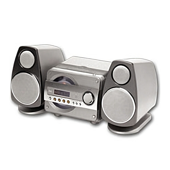
Micro Component System
FILE NO.
DC-MCR60
PRODUCT CODE No.
129 684 07
(DECK) ........................................................................... 24
(AMPLIFIER) .................................................................. 26
(TUNER) ........................................................................ 28
Wiring diagram
(CD & SYSCON) ........................................................... 20
(FRONT) ....................................................................... 23
(DECK) .......................................................................... 25
(AMPLIFIER & TUNER) ................................................ 30
(PRIMARY POWER SUPPLY) ...................................... 32
(SECONDARY POWER SUPPLY) ............................... 32
(SWITCH) ...................................................................... 32
Wiring connection ............................................................. 33
REFERENCE No.
(AU)
SM
5810603
Advertisement

Related Manuals for Sanyo DC-MCR60


Summary of Contents for Sanyo DC-MCR60
-
Page 1: Table Of Contents
All manuals and user guides at all-guides.com FILE NO. Service Manual Micro Component System DC-MCR60 (AU) Contents PRODUCT CODE No. 129 684 07 Laser beam safety precaution ........... 1 (DECK) ................24 Tape adjustments ............. 1 (AMPLIFIER) ..............26 Tuner adjustments ............2 (TUNER) ................ -
Page 2: Laser Beam Safety Precaution
All manuals and user guides at all-guides.com LASER BEAM SAFETY PRECAUTION • Pick-up that emits a laser beam is used in this CD player section. CAUTION : THIS PRODUCT CONTAINS A LOW POWER LASER DEVICE, TO ENSURE CONTINUED SAFETY DO NOT REMOVE ANY COVERS OR ATTEMPT TO GAIN ACCESS TO THE INSIDE OF THE PRODUCT. -
Page 3: Tuner Adjustments
Clean a lens with swab of the cotton which moistened it with alcohol, cleaning paper or cleaning disc appointed. Specified cleaning disc : LC-1 (Part code : 645 026 1961 ..manufactured by SANYO.) Show a clean procedure in the following in reference by swab of cotton. -
Page 4: Exploded View
All manuals and user guides at all-guides.com EXPLODED VIEW - 3 -... -
Page 5: Parts List
All manuals and user guides at all-guides.com PARTS LIST PRODUCT SAFETY NOTICE EACH PRECAUTION IN THIS MANUAL SHOULD BE FOLLOWED DURING SERVICING. COMPONENTS IDENTIFIED WITH THE IEC SYMBOL IN THE PARTS LIST AND THE SCHEMATIC DIAGRAM DESIGNATED COMPONENTS IN WHICH SAFETY AND ! ! ! PERFORMANCE CAN BE OF SPECIAL SIGNIFICANCE. - Page 6 All manuals and user guides at all-guides.com PARTS LIST REF.NO. PART NO. DESCRIPTION REF.NO. PART NO. DESCRIPTION 614 274 2013 CORD,ID CONNECTOR BR604 614 327 7989 REFLECTOR,LCD 423 016 7908 FUSE 250V 2.5A CN601 645 063 8695 SOCKET,FPC 22P,FRONT-MCON 645 066 7701 TRANS,POWER CN603 645 063 8701 SOCKET,FPC 16P,FRONT-MCON 645 068 1059 CORD,POWER-2.0MK...
- Page 7 All manuals and user guides at all-guides.com PARTS LIST AMPLIFIER & TUNER P.W.BOARD ASSY REF.NO. PART NO. DESCRIPTION Q2003 405 017 9709 TR 2SC3330-U REF.NO. PART NO. DESCRIPTION 405 017 9600 TR 2SC3330-T 614 328 8404 ASSY,PWB,AMP-TU(Only initial) 405 011 8609 TR 2SC1740S-S C4714 403 058 4608 POLYESTER 0.15U J 50V 405 011 8500 TR 2SC1740S-R...
-
Page 8: Ic Block Diagram & Description
All manuals and user guides at all-guides.com PARTS LIST SECONDARY POWER SUPPLY P.W.BOARD ASSY REF.NO. PART NO. DESCRIPTION XF210 645 059 0047 FILTER,BP REF.NO. PART NO. DESCRIPTION 645 026 2975 FILTER,BP 108MHZ 614 328 4482 ASSY,PWB,PT2(Only initial) 614 252 1045 FILTER,LC CN451 614 017 8203 TERMINAL BOARD XF211... - Page 9 All manuals and user guides at all-guides.com IC BLOCK DIAGRAM & DESCRIPTION IC101 LA9242M-MPB (Servo Processing Signal for CD Player) Vcc1 BH1 PH1 VR REF1 Vcc2 DRF CE DAT CL CLK 54 53 RF DET FIN2 FIN1 DGND INTER FACE RFS- RF Amp RFSM...
- Page 10 All manuals and user guides at all-guides.com IC BLOCK DIAGRAM & DESCRIPTION IC102 LC78629E (DSP for CD Player) DEFI EFLG SBSY XVSS VVSS ISET XOUT VVDD XVDD MUTER CONT8 RVDD EFMO RCHO EFMIN RVSS TEST2 LVSS CLV+ LCHO CLV- LVDD V *P MUTEL CONT7 PCCL...
- Page 11 All manuals and user guides at all-guides.com IC BLOCK DIAGRAM & DESCRIPTION IC102 LC78629E (DSP for CD Player) TST11 TEST2 TEST4 EFMO PDO ISET FR TEST1 TEST3 TEST5 VDD3V 59 64 11 32 33 62 RAM Address Slice level 8bits DEFI VCO Clock Oscillator Control...
- Page 12 All manuals and user guides at all-guides.com IC BLOCK DIAGRAM & DESCRIPTION IC211 LA1844ML (Electronic Tuning-Supported Home Audio Tuner IC) RF.AMP PILOT DECODER BUFF CANCEL ANTI-BIRDIE P-DET STEREO LEVEL AM/FM COMP S-CURVE BUFF PILOT 304kHz TUNING DRIVE IC412 TA8229 (Audio Power IC) IC510 BA3314F (Dual Pre Amp for Audio) VCC2 VCC1...
- Page 13 All manuals and user guides at all-guides.com IC BLOCK DIAGRAM & DESCRIPTION IC601 LC72338-9C10 (Single-Chip PLL + Controller) 77 E01 DIVIDER REFERENCE DIVIDER SELECTER PHASE DETECTOR XOUT COM1 COMMON COM2 DRIVER COM3 UNLOCK 1 / 16,1 / 17 FMIN PROGRAMMABLE DIVIDER Vdd1 Vdd2 AMIN...
- Page 14 All manuals and user guides at all-guides.com IC BLOCK DIAGRAM & DESCRIPTION IC601 LC72338-9C10 (Single-Chip PLL + Controller) PIn name Pin No. I/O I/O Format Functions PIn name Pin No. I/O I/O Format Functions Universal counter (freqency and period measurement) / general- Port only for key return signal input.