Table of Contents
Advertisement
Advertisement
Table of Contents

Related Manuals for Huawei RRU3971


Summary of Contents for Huawei RRU3971
- Page 1 Issue Date HUAWEI TECHNOLOGIES CO., LTD.
- Page 2 All other trademarks and trade names mentioned in this document are the property of their respective holders. Notice The purchased products, services and features are stipulated by the contract made between Huawei and the customer. All or part of the products, services and features described in this document may not be within the purchase scope or the usage scope.
-
Page 3: About This Document
About This Document About This Document Purpose This document describes the process of installing DC blade RRU3971 (referred to as RRU in this document). Product Versions The following table lists the product versions related to this document. Product Name Solution Version... - Page 4 Indicates an imminently hazardous situation which, if not avoided, will result in death or serious injury. Indicates a potentially hazardous situation which, if not avoided, could result in death or serious injury. Issue () Huawei Proprietary and Confidential Copyright © Huawei Technologies Co., Ltd.
- Page 5 One item is selected. [ x | y | ... ] Optional items are grouped in brackets and separated by vertical bars. One item is selected or no item is selected. Issue () Huawei Proprietary and Confidential Copyright © Huawei Technologies Co., Ltd.
- Page 6 Action Description Click Select and release the primary mouse button without moving the pointer. Double-click Press the primary mouse button twice continuously and quickly without moving the pointer. Issue () Huawei Proprietary and Confidential Copyright © Huawei Technologies Co., Ltd.
- Page 7 About This Document Action Description Drag Press and hold the primary mouse button and move the pointer to a certain position. Issue () Huawei Proprietary and Confidential Copyright © Huawei Technologies Co., Ltd.
-
Page 8: Table Of Contents
Contents Contents About This Document........................ii 1 Changes in RRU3971 Installation Guide..................1 2 Installation Preparations......................2 2.1 Reference Documents..............................3 2.2 Tools and Instruments..............................3 2.3 Skills and Requirements for Onsite Personnel.......................5 3 Information About the Installation...................6 3.1 RRU Exterior..................................7 3.2 RRU Ports..................................8 3.3 RRU Indicators................................10 3.4 Installation Scenarios..............................12... - Page 9 9 Checking the RRU Hardware Installation................118 10 Powering On an RRU......................119 11 Appendix...........................121 11.1 Adding a Tool-Less Female Connector (Pressfit Type) to the RRU Power Cable on the RRU Side......122 Issue () Huawei Proprietary and Confidential viii Copyright © Huawei Technologies Co., Ltd.
-
Page 10: Changes In Rru3971 Installation Guide
1 Changes in RRU3971 Installation Guide Changes in RRU3971 Installation Guide This section describes the changes in the RRU3971 Installation Guide. Draft A (2015-09-30) This is a draft. Issue () Huawei Proprietary and Confidential Copyright © Huawei Technologies Co., Ltd. -
Page 11: Installation Preparations
2.3 Skills and Requirements for Onsite Personnel Onsite personnel must be qualified and trained. Before performing any operation, onsite personnel must be familiar with correct operation methods and safety precautions. Issue () Huawei Proprietary and Confidential Copyright © Huawei Technologies Co., Ltd. -
Page 12: Reference Documents
You must prepare the following tools and instruments before the installation. Hammer drill (a φ12 bit) ESD gloves Vacuum cleaner Heat gun Phillips screwdriver (M3 to Flat-head screwdriver (M3 to Rubber mallet COAX crimping tool Wire stripper Issue () Huawei Proprietary and Confidential Copyright © Huawei Technologies Co., Ltd. - Page 13 (M3 to M6) Multimeter Measuring tape Marker (diameter ≤ 10 mm [0.39 in.]) Inner hexagon wrench Fixed pulley(weight-bearing Lifting sling capacity > 500 kg or 1102.5 5 mm Hydraulic pliers Issue () Huawei Proprietary and Confidential Copyright © Huawei Technologies Co., Ltd.
-
Page 14: Skills And Requirements For Onsite Personnel
Before the installation, pay attention to the following items: The customer's technical engineers must be trained by Huawei and be familiar with the proper installation and operation methods. The number of onsite personnel depends on the engineering schedule and installation environment. -
Page 15: Information About The Installation
3.5 Installation Clearance Requirements of an RRU This section describes the requirements for the installation clearance of a single RRU and multiple RRUs and the requirements for the installation spacing between RRUs. Issue () Huawei Proprietary and Confidential Copyright © Huawei Technologies Co., Ltd. -
Page 16: Rru Exterior
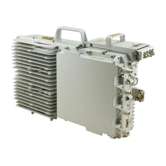
This section describes the exterior and dimensions of an RRU. Figure 3-1 shows the exterior of an RRU. Figure 3-1 RRU exterior Figure 3-2 shows RRU dimensions. Figure 3-2 RRU dimensions Issue () Huawei Proprietary and Confidential Copyright © Huawei Technologies Co., Ltd. -
Page 17: Rru Ports
This section describes ports on the RRU panels. An RRU has a bottom panel, cabling cavity panel, and indicator panel. Figure 3-4 shows the ports on the RRU panels. Issue () Huawei Proprietary and Confidential Copyright © Huawei Technologies Co., Ltd. - Page 18 Power supply socket, for details about RRU cavity power cable experience and specifications, NEG(-) see RRU Power Cable. CPRI0 Optical/electrical port 0, connected to the CPRI1 Optical/electrical port 1, connected to the Issue () Huawei Proprietary and Confidential Copyright © Huawei Technologies Co., Ltd.
-
Page 19: Rru Indicators
Color Status Meaning Green Steady on The power input is available, but the board is faulty. Steady off No power input is available or the board is faulty. Issue () Huawei Proprietary and Confidential Copyright © Huawei Technologies Co., Ltd. - Page 20 CPRI ports. Steady off The optical module cannot be detected or is powered off. CPRI1 Red and Steady green The CPRI link is running properly. green Issue () Huawei Proprietary and Confidential Copyright © Huawei Technologies Co., Ltd.
-
Page 21: Installation Scenarios
RRU mounting kits in assembled installation mode are not allowed in indoor scenarios. NOTICE If the RRU is inappropriately installed, heat dissipation of the RRU deteriorates and the RRU may not work properly, as shown in Figure 3-5. Issue () Huawei Proprietary and Confidential Copyright © Huawei Technologies Co., Ltd. - Page 22 RRUs on the auxiliary pole. Figure 3-6 Requirements for the vertical deviation angle of an RRU (1) RRU (2) Installation support (pole, U-steel, angle steel, or wall) Issue () Huawei Proprietary and Confidential Copyright © Huawei Technologies Co., Ltd.
- Page 23 RRUs. l The recommended thickness of the pole wall is 3.5 mm (0.14 in.) or above. Figure 3-8 shows a single RRU installed on a pole. Issue () Huawei Proprietary and Confidential Copyright © Huawei Technologies Co., Ltd.
- Page 24 RRUs installed on a pole. Figure 3-9 Two RRUs installed on a pole Figure 3-10, Figure 3-11, and Figure 3-12 show multiple RRUs installed on a pole. Issue () Huawei Proprietary and Confidential Copyright © Huawei Technologies Co., Ltd.
- Page 25 3 Information About the Installation Figure 3-10 Three RRUs installed on a pole Figure 3-11 Four RRUs installed on a pole Issue () Huawei Proprietary and Confidential Copyright © Huawei Technologies Co., Ltd.
- Page 26 Figure 3-13 shows U-steel specifications. Figure 3-13 U-steel specifications NOTICE U-steel only supports the standard installation of a single RRU. Figure 3-14 shows an RRU installed on U-steel. Issue () Huawei Proprietary and Confidential Copyright © Huawei Technologies Co., Ltd.
- Page 27 Figure 3-15 Angle steel specifications NOTICE Angle steel only supports the standard installation of a single RRU. Figure 3-16 shows an RRU installed on angle steel. Issue () Huawei Proprietary and Confidential Copyright © Huawei Technologies Co., Ltd.
- Page 28 When RRUs are installed on a wall in side-mounted mode, do not combine mounting brackets for multiple RRUs, as shown in Figure 3-17. Figure 3-17 Correct installation of mounting brackets for multiple RRUs installed on a wall in side-mounted mode Issue () Huawei Proprietary and Confidential Copyright © Huawei Technologies Co., Ltd.
- Page 29 RRUs" in 3900 Series Base Station Technical Description. NOTICE The mounting brackets for multiple RRUs cannot be combined when the RRUs are installed on an IFS06, as shown in Figure 3-19. Issue () Huawei Proprietary and Confidential Copyright © Huawei Technologies Co., Ltd.
- Page 30 3 Information About the Installation Figure 3-19 Correct installation of mounting brackets for RRUs installed on an IFS06 Figure 3-20 Figure 3-21 show RRUs installed on an IFS06. Issue () Huawei Proprietary and Confidential Copyright © Huawei Technologies Co., Ltd.
- Page 31 3 Information About the Installation Figure 3-20 Three RRUs installed on an IFS06 (1) Height-restricted scenario (2) Height-unrestricted scenario Issue () Huawei Proprietary and Confidential Copyright © Huawei Technologies Co., Ltd.
-
Page 32: Installation Clearance Requirements Of An Rru
RRUs and the requirements for the installation spacing between RRUs. 3.5.1 Clearance for a Single RRU This section describes the recommended and minimum clearances for a single RRU. Issue () Huawei Proprietary and Confidential Copyright © Huawei Technologies Co., Ltd. - Page 33 Clearance for a Single RRU in Side-Mounted Mode Figure 3-22 shows the clearance for a single RRU in side-mounted mode. Issue () Huawei Proprietary and Confidential Copyright © Huawei Technologies Co., Ltd.
- Page 34 Figure 3-22 Clearance for a single RRU in side-mounted mode Clearance for a Single RRU in Standard Mode Figure 3-23 shows the clearance for a single RRU in standard mode. Issue () Huawei Proprietary and Confidential Copyright © Huawei Technologies Co., Ltd.
- Page 35 Figure 3-23 Clearance for a single RRU in standard mode Clearance for a Single Tower-Mounted RRU Figure 3-24 Figure 3-25 show the minimum clearances for a single RRU in side-mounted mode and standard mode on a tower. Issue () Huawei Proprietary and Confidential Copyright © Huawei Technologies Co., Ltd.
-
Page 36: Clearance For Three Or More Rrus
Figure 3-25 Minimum clearance for a single RRU in standard mode on a tower 3.5.2 Clearance for Three or More RRUs This section describes the recommended and minimum clearances for three or more RRUs. Issue () Huawei Proprietary and Confidential Copyright © Huawei Technologies Co., Ltd. - Page 37 Figure 3-26 Recommended clearances for three or more RRUs installed in centralized mode Minimum Clearances for Three or More RRUs Installed in Centralized Mode Figure 3-27 shows the minimum clearances for three or more RRUs installed in centralized mode. Issue () Huawei Proprietary and Confidential Copyright © Huawei Technologies Co., Ltd.
- Page 38 Recommended Clearances for Three or More RRUs Installed in Standard Mode on a Wall Figure 3-28 shows the recommended clearances for three or more RRUs installed in standard mode on a wall. Issue () Huawei Proprietary and Confidential Copyright © Huawei Technologies Co., Ltd.
- Page 39 RRUs installed in standard mode on a wall. Figure 3-29 Minimum clearances for three or more RRUs installed in standard mode on a wall Issue () Huawei Proprietary and Confidential Copyright © Huawei Technologies Co., Ltd.
-
Page 40: Installation Spacing Between Rrus
This section describes the horizontal and vertical spacing between RRUs. Recommended Horizontal Spacing Between RRUs Figure 3-31 shows the recommended horizontal spacing between RRUs. Figure 3-31 Recommended horizontal spacing between RRUs Issue () Huawei Proprietary and Confidential Copyright © Huawei Technologies Co., Ltd. - Page 41 Figure 3-32 Minimum horizontal spacing between RRUs Recommended Vertical Spacing Between RRUs Figure 3-33 shows the recommended vertical spacing between RRUs. Figure 3-33 Recommended vertical spacing between RRUs Issue () Huawei Proprietary and Confidential Copyright © Huawei Technologies Co., Ltd.
- Page 42 3 Information About the Installation Minimum Vertical Spacing Between RRUs Figure 3-34 shows the minimum vertical spacing between RRUs. Figure 3-34 Minimum vertical spacing between RRUs Issue () Huawei Proprietary and Confidential Copyright © Huawei Technologies Co., Ltd.
-
Page 43: Unpacking The Equipment
The total number does not tally with the Find out the cause and report any missing packing list articles to the local Huawei office. Step 2 Check the exterior of the packing case. Issue () Huawei Proprietary and Confidential... - Page 44 Sign the Packing List with the customer. those on the packing list Either shipment shortage, wrong shipment Report to the local Huawei office. or damaged articles. CAUTION l To protect the equipment and prevent damage to the equipment, you are advised to keep the...
-
Page 45: Installation Process
The installation process involves installing an RRU and RRU cables, checking the RRU hardware installation, and powering on an RRU. Figure 5-1 shows the installation process. Figure 5-1 Process of installing an RRU Issue () Huawei Proprietary and Confidential Copyright © Huawei Technologies Co., Ltd. -
Page 46: Hoisting An Rru And Related Cables Onto A Tower
6.3 Hoisting Power Cables onto a Tower This section describes the procedure for hoisting power cables onto a tower and the precautions that must be taken. Issue () Huawei Proprietary and Confidential Copyright © Huawei Technologies Co., Ltd. -
Page 47: Hoisting An Rru Onto A Tower
Figure 6-1. Then technician B pulls the lifting sling downwards, and technician C pulls the traction sling outwards to protect the mounting kits from colliding with the tower. Issue () Huawei Proprietary and Confidential Copyright © Huawei Technologies Co., Ltd. - Page 48 Step 5 Technician C binds the RRU using the lifting sling and traction sling, as shown in Figure 6-2. The binding methods in Figure 6-3 Figure 6-4 are incorrect. Issue () Huawei Proprietary and Confidential Copyright © Huawei Technologies Co., Ltd.
- Page 49 6 Hoisting an RRU and Related Cables onto a Tower Figure 6-2 Binding the RRU (1) Handle (2) Lifting sling (3) Traction eye (4) Traction sling Figure 6-3 Incorrect binding method (1) Issue () Huawei Proprietary and Confidential Copyright © Huawei Technologies Co., Ltd.
- Page 50 C pulls the traction sling outwards to protect the RRU from colliding with the tower. Figure 6-5 Hoisting the RRU onto the tower (1) Lifting sling (2) Fixed pulley (3) Traction sling Issue () Huawei Proprietary and Confidential Copyright © Huawei Technologies Co., Ltd.
-
Page 51: Hoisting Fiber Optic Cables Onto A Tower
Cabling requirements for power cables are met. For details, see 8.1 Cabling Requirements. Procedure Step 1 Hoist the fiber optic cables onto the tower, as shown in Figure 6-6. Issue () Huawei Proprietary and Confidential Copyright © Huawei Technologies Co., Ltd. - Page 52 4 m (13.12 ft) away from the lifting sling, as shown in Figure 6-7. Issue () Huawei Proprietary and Confidential Copyright © Huawei Technologies Co., Ltd.
- Page 53 Installation engineer C pulls the lifting sling downwards, and installation engineer D pulls the traction sling outwards to protect the fiber optic cables from colliding with the tower. Issue () Huawei Proprietary and Confidential Copyright © Huawei Technologies Co., Ltd.
-
Page 54: Hoisting Power Cables Onto A Tower
Step 1 Hoist the power cables onto the tower, as shown in Figure 6-9. Figure 6-9 Hoisting power cables onto the tower (1) Lifting sling (2) Fixed pulley Issue () Huawei Proprietary and Confidential Copyright © Huawei Technologies Co., Ltd. - Page 55 Wrap the PVC insulation tape from 30 mm (1.18 in.) away from one end of the connector until it reaches the other end of the connector. The total length of the wrapped connector is 100 mm (3.94 in.). Issue () Huawei Proprietary and Confidential Copyright © Huawei Technologies Co., Ltd.
- Page 56 Step 3 Remove the cable ties, PVC insulation tape, and lifting sling. NOTE The procedure for hoisting the power cables onto the tower is for your reference only. ----End Issue () Huawei Proprietary and Confidential Copyright © Huawei Technologies Co., Ltd.
-
Page 57: Installing The Rru
This section describes the procedure and precautions for installing an RRU on a wall. 7.6 Installing an RRU on an IFS06 This section describes the procedure and precautions for installing an RRU on an IFS06. Issue () Huawei Proprietary and Confidential Copyright © Huawei Technologies Co., Ltd. -
Page 58: Mounting Kits For An Rru
When the operator faces the RRU whose handle and cabling cavity are on the right-hand side, the side facing the operator is the front of the RRU. Figure 7-2 shows the bracket assembly for an RRU. Issue () Huawei Proprietary and Confidential Copyright © Huawei Technologies Co., Ltd. -
Page 59: Installing The Rru On A Pole
Do not stand an RRU upright because the RF ports cannot support the weight of the RRU. l Place a foam pad or cardboard under an RRU to protect the RRU housing from damage during the installation. Issue () Huawei Proprietary and Confidential Copyright © Huawei Technologies Co., Ltd. - Page 60 3.5 Installation Clearance Requirements of an RRU needs to be provided. Step 2 Install the RRU mounting brackets, as shown in Figure 7-4. Figure 7-4 Installing the RRU mounting brackets Issue () Huawei Proprietary and Confidential Copyright © Huawei Technologies Co., Ltd.
- Page 61 Figure 7-5 Securing the RRU mounting brackets Step 4 Install the RRU onto the main bracket, as shown in Figure 7-6. Issue () Huawei Proprietary and Confidential Copyright © Huawei Technologies Co., Ltd.
-
Page 62: Installing Two Rrus
7.2.2 Installing Two RRUs This section describes the procedure and precautions for installing two RRUs on a pole. Prerequisites The hoist clamp on the main bracket is secured properly. Issue () Huawei Proprietary and Confidential Copyright © Huawei Technologies Co., Ltd. - Page 63 Step 2 Use an M6 inner hexagon screwdriver to loosen the four hex socket screws from the main bracket and pole installation brackets on the second set of mounting brackets, and remove the main bracket, as shown in Figure 7-9. Issue () Huawei Proprietary and Confidential Copyright © Huawei Technologies Co., Ltd.
- Page 64 The main mounting bracket for installing a blade RRU can connect to the main mounting bracket for installing a common RRU in the scenarios of adding RRUs, as shown in Figure 7-11. Issue () Huawei Proprietary and Confidential Copyright © Huawei Technologies Co., Ltd.
- Page 65 5 N·m (44.25 lbf·in.) so that the attachment plate and main bracket are firmly secured, as shown in Figure 7-13 Issue () Huawei Proprietary and Confidential Copyright © Huawei Technologies Co., Ltd.
- Page 66 RRU. Then, rotate the sheet metal tab to align the vacant hole in the sheet metal tab with a hole on the top of the first RRU. Issue () Huawei Proprietary and Confidential Copyright © Huawei Technologies Co., Ltd.
-
Page 67: Installing Three Or More Rrus
RRUs on a pole. Procedure Step 1 Install two RRUs, as shown in Figure 7-15. For detailed installation process, see 7.2.2 Installing RRUs. Figure 7-15 Two RRUs installed on a pole Issue () Huawei Proprietary and Confidential Copyright © Huawei Technologies Co., Ltd. - Page 68 RRU to 5 N·m (44.25 lbf·in.), as shown in Figure 7-17. NOTICE The third main bracket must be installed, with the open ends of U-shaped slots on both sides facing downwards. Issue () Huawei Proprietary and Confidential Copyright © Huawei Technologies Co., Ltd.
- Page 69 (1) Main mounting bracket for a blade RRU (2) Main mounting bracket for a common RRU Step 4 Install the sheet metal tab for fixing the neighboring RRUs, as shown in Figure 7-19. Issue () Huawei Proprietary and Confidential Copyright © Huawei Technologies Co., Ltd.
- Page 70 Step 5 Install the second set of RRU mounting brackets at least 80 mm (3.15 in.) above or below the first set of RRU mounting brackets, as shown in Figure 7-20. Issue () Huawei Proprietary and Confidential Copyright © Huawei Technologies Co., Ltd.
- Page 71 5 N·m (44.25 lbf·in.) so that the attachment plate and main bracket are firmly secured, as shown in Figure 7-21. Figure 7-21 Installing the fourth RRU on the fourth main bracket Issue () Huawei Proprietary and Confidential Copyright © Huawei Technologies Co., Ltd.
-
Page 72: Installing An Rru On U-Steel
RRU installed on U-steel. NOTICE When the width of the narrower edges of the U-steel is less than 40 mm (1.57 in.), only the a and b modes are supported. Issue () Huawei Proprietary and Confidential Copyright © Huawei Technologies Co., Ltd. - Page 73 3.5.1 Clearance for a Single RRU. If the RRU is installed on the ground, determine a position for installing the mounting brackets according to the instructions in Figure 7-23. Issue () Huawei Proprietary and Confidential Copyright © Huawei Technologies Co., Ltd.
- Page 74 Adjust the position of the nut and remove the square-neck bolt at the open end from the slot on the auxiliary bracket. Slide the mounting brackets onto the U-steel horizontally and insert the square-neck bolt into the slot. Issue () Huawei Proprietary and Confidential Copyright © Huawei Technologies Co., Ltd.
- Page 75 Step 4 Use an inner hexagon torque screwdriver to remove the attachment plate from one side of the RRU, reinstall the attachment plate onto the rear of the RRU, and tighten the four stainless screws to 5 N·m (44.25 lbf·in.), as shown in Figure 7-26. Issue () Huawei Proprietary and Confidential Copyright © Huawei Technologies Co., Ltd.
- Page 76 5 N·m (44.25 lbf·in.) so that the attachment plate and main bracket are firmly secured, as shown in Figure 7-28. Issue () Huawei Proprietary and Confidential Copyright © Huawei Technologies Co., Ltd.
-
Page 77: Installing An Rru On Angle Steel
Place a foam pad or cardboard under an RRU to protect the RRU housing from damage during the installation. Context Figure 7-29 shows the top view of an RRU installed on angle steel. Issue () Huawei Proprietary and Confidential Copyright © Huawei Technologies Co., Ltd. - Page 78 1200 mm (47.24 in.) to 1600 mm (59.06 in.) high above the ground. If the space is insufficient, only 3.5 Installation Clearance Requirements of an RRU needs to be provided. Issue () Huawei Proprietary and Confidential Copyright © Huawei Technologies Co., Ltd.
- Page 79 Tighten the nuts on the two square-neck bolts synchronously. After the main and auxiliary brackets are secured properly, measure the spacing between the brackets on both sides and ensure that the spacing is the same on the two sides. Issue () Huawei Proprietary and Confidential Copyright © Huawei Technologies Co., Ltd.
- Page 80 Figure 7-33. Figure 7-33 Installing the attachment plate onto the rear of the RRU Step 5 Install the RRU onto the main bracket, as shown in Figure 7-34. Issue () Huawei Proprietary and Confidential Copyright © Huawei Technologies Co., Ltd.
- Page 81 5 N·m (44.25 lbf·in.) so that the attachment plate and main bracket are firmly secured, as shown in Figure 7-35. Figure 7-35 Securing the captive screw into the connection hole ----End Issue () Huawei Proprietary and Confidential Copyright © Huawei Technologies Co., Ltd.
-
Page 82: Installing An Rru On A Wall
Figure 7-36 Disassembling the RRU mounting brackets (1) Main bracket (2) Square-neck bolt (3) Pole installation bracket (4) Auxiliary bracket (5) Flat washer (6) Spring washer (7) Nut (8) Plastic screw cap Issue () Huawei Proprietary and Confidential Copyright © Huawei Technologies Co., Ltd. - Page 83 3.5 Installation Clearance Requirements of an RRU needs to be provided. Step 3 Drill holes at the anchor points, and then insert expansion anchor bolts, as shown in Figure 7-38. Issue () Huawei Proprietary and Confidential Copyright © Huawei Technologies Co., Ltd.
- Page 84 16 mm (0.63 in.) torque socket to tighten the nuts to 30 N·m (265.52 lbf·in.), as shown in Figure 7-39. Issue () Huawei Proprietary and Confidential Copyright © Huawei Technologies Co., Ltd.
- Page 85 5 N·m (44.25 lbf·in.) so that the main bracket and pole installation bracket are firmly secured, as shown in Figure 7-40. Figure 7-40 Installing the main bracket Issue () Huawei Proprietary and Confidential Copyright © Huawei Technologies Co., Ltd.
- Page 86 Figure 7-41 Installing the attachment plate onto the rear of the RRU Step 7 Install the RRU onto the main bracket, as shown in Figure 7-42. Figure 7-42 Installing the RRU onto the main bracket Issue () Huawei Proprietary and Confidential Copyright © Huawei Technologies Co., Ltd.
-
Page 87: Installing An Rru On An Ifs06
RRUs can be installed on an IFS06 when the ambient temperature is higher than or equal to the lowest operating temperature of the RRUs and at least 5°C (41°F) lower than the Issue () Huawei Proprietary and Confidential Copyright © Huawei Technologies Co., Ltd. - Page 88 Use an M10 torque wrench to loosen the nuts on the two square-neck bolts, and remove the plastic screw cap, nuts, spring washers, flat washers, square-neck bolts, and pole installation bracket from the auxiliary bracket. Issue () Huawei Proprietary and Confidential Copyright © Huawei Technologies Co., Ltd.
- Page 89 Step 3 Attach the main bracket to the pole installation bracket, and use an inner hexagon screwdriver to tighten four M6x16 screws to 5 N·m (44.25 lbf·in.) so that the main bracket and pole installation bracket are firmly secured, as shown in Figure 7-46. Issue () Huawei Proprietary and Confidential Copyright © Huawei Technologies Co., Ltd.
- Page 90 5 N·m (44.25 lbf·in.) so that the attachment plate and main bracket are firmly secured, as shown in Figure 7-47. Issue () Huawei Proprietary and Confidential Copyright © Huawei Technologies Co., Ltd.
- Page 91 7 Installing the RRU Figure 7-47 Installing the RRU onto the main bracket Step 5 Install the RRUs on the lower level from left to right, as shown in Figure 7-48. Issue () Huawei Proprietary and Confidential Copyright © Huawei Technologies Co., Ltd.
- Page 92 RRU and at least 10°C (10°F) lower than the highest operating temperature of the RRU, repeat the preceding steps to install the RRUs on the higher level, as shown in Figure 7-49. Issue () Huawei Proprietary and Confidential Copyright © Huawei Technologies Co., Ltd.
- Page 93 7 Installing the RRU Figure 7-49 Installing RRUs on the higher level ----End Issue () Huawei Proprietary and Confidential Copyright © Huawei Technologies Co., Ltd.
-
Page 94: Installing Rru Cables
This section describes the procedure for installing a CPRI optical cable. 8.11 Installing an RRU Power Cable This section describes the procedure for installing an RRU power cable. 8.12 Closing the Cover Plate of an RRU Cabling Cavity Issue () Huawei Proprietary and Confidential Copyright © Huawei Technologies Co., Ltd. - Page 95 8 Installing RRU Cables This section describes the procedure for closing the cover plate of an RRU cabling cavity. Issue () Huawei Proprietary and Confidential Copyright © Huawei Technologies Co., Ltd.
-
Page 96: Cabling Requirements
Reserve a proper distance (0.1 m or 3.937 in. is recommended) between equipment and cables especially at the cable curves to protect the cables and equipment. Indoor cabling requirements Route each cable into the room through the feeder window. Issue () Huawei Proprietary and Confidential Copyright © Huawei Technologies Co., Ltd. - Page 97 A 3-hole clip is shown by illustration a in the following figure. It is often used to fasten feeders. A 6-hole clip is shown by illustration b in the following figure. It is often used to fasten power cables and CPRI fiber optic cables. Issue () Huawei Proprietary and Confidential Copyright © Huawei Technologies Co., Ltd.
- Page 98 The following figure shows the cables secured on a cable tray. Figure 8-2 Cables secured on a cable tray (1) 3-hole clip (2) 6-hole clip The following figure shows the cables secured on a tower. Issue () Huawei Proprietary and Confidential Copyright © Huawei Technologies Co., Ltd.
- Page 99 Cables can only be laid out under well-planned instructions. The cabling activities of fiber optic cables are allowed only when qualified personnel and communication facilities are available. Do not circle and twist cables. Issue () Huawei Proprietary and Confidential Copyright © Huawei Technologies Co., Ltd.
- Page 100 E1 cables must not be pressed by the door of the cabinet when routed, as shown in the following figure. Figure 8-4 E1 cables routed in the cabinet Cabling of fiber optic cables Issue () Huawei Proprietary and Confidential Copyright © Huawei Technologies Co., Ltd.
- Page 101 Unused optical connectors must be covered with dustproof caps. The fiber optic cables must not be pressed by the door of the cabinet when routed, as shown in the following figures. Issue () Huawei Proprietary and Confidential Copyright © Huawei Technologies Co., Ltd.
- Page 102 After routing a fiber optic cable onto the platform on a tower, route it along the shortest path to the rails surrounding the platform, and route it along the inside of the rails. Issue () Huawei Proprietary and Confidential Copyright © Huawei Technologies Co., Ltd.
-
Page 103: Rru Cable Connections
(3) RRU AISG multi-wire cable (4) RRU AISG extension cable (5) RRU power cable (6) CPRI optical fiber (7) RRU alarm cable Figure 8-10 shows the cable connections of a multimode RRU. Issue () Huawei Proprietary and Confidential Copyright © Huawei Technologies Co., Ltd. - Page 104 (3) RRU AISG multi-wire cable (4) RRU AISG extension cable (5) RRU power cable (6) CPRI optical fiber (7) RRU alarm cable Figure 8-11 shows the cable connections of multiple single-mode RRUs. Issue () Huawei Proprietary and Confidential Copyright © Huawei Technologies Co., Ltd.
- Page 105 Figure 8-11 Cable connections of multiple single-mode RRUs (1) RRU PGND cable (2) RRU RF jumper (3) RRU power cable (4) CPRI optical fiber Figure 8-12 shows the cable connections of multiple multimode RRUs. Issue () Huawei Proprietary and Confidential Copyright © Huawei Technologies Co., Ltd.
-
Page 106: Installing Rru Cables
Figure 8-12 Cable connections of multiple multimode RRUs 8.3 Installing RRU Cables This chapter describes the procedure for installing RRU cables. Figure 8-13 shows the procedure for installing RRU cables. Issue () Huawei Proprietary and Confidential Copyright © Huawei Technologies Co., Ltd. -
Page 107: Rru Cables
Position Position RRU PGND OT terminal Ground OT terminal Ground terminal Cable terminal on the on the ground (M6, 16 mm (M8, 16 mm 0.025 in. 0.025 in. Issue () Huawei Proprietary and Confidential Copyright © Huawei Technologies Co., Ltd. -
Page 108: Installing An Rru Pgnd Cable
OT terminal at one end and an M8 terminal at the other end. DANGER Install RRU PGND cables by strictly following the following operations. Otherwise, damage to the RRU or personal injury may occur. Issue () Huawei Proprietary and Confidential Copyright © Huawei Technologies Co., Ltd. - Page 109 Therefore, when installing a PGND cable on a ground terminal, remove the screws on the other ground terminal before installing the RRU. l Crimp OT terminals in correct positions, as shown in Figure 8-15. Issue () Huawei Proprietary and Confidential Copyright © Huawei Technologies Co., Ltd.
-
Page 110: Installing An Rru Rf Jumper
Step 1 Connect the 4.3-10 straight male connector on the RRU RF jumper to the antenna port, and use a torque wrench to tighten the connector to 5 N·m (44.25 lbf·in.), as shown in Figure 8-16. Figure 8-16 Installing an RRU RF jumper Issue () Huawei Proprietary and Confidential Copyright © Huawei Technologies Co., Ltd. - Page 111 Start wrapping the connector at a position 50 mm (1.97 in.) away below the bottom of the connector to the top of the connector, first from bottom Issue () Huawei Proprietary and Confidential Copyright © Huawei Technologies Co., Ltd.
- Page 112 Cut off the redundant tape after three layers are wrapped. Wrap each layer of tape around the connector tightly. Issue () Huawei Proprietary and Confidential Copyright © Huawei Technologies Co., Ltd.
-
Page 113: Installing An Rru Aisg Multi-Wire Cable And Aisg Extension Cable
Link the waterproofed DB9 connector at one end the AISG multi-wire cable to the RET port on the RRU bottom, as shown in Figure 8-19. Issue () Huawei Proprietary and Confidential Copyright © Huawei Technologies Co., Ltd. - Page 114 Link the waterproofed DB9 connector at one end of the AISG multi-wire cable to the RET port on the RRU bottom, and link the other end to the standard AISG male connector of the AISG extension cable, as shown in Figure 8-20. Issue () Huawei Proprietary and Confidential Copyright © Huawei Technologies Co., Ltd.
- Page 115 Connect the other end of the AISG extension cable to the standard AISG male connector on the RCU, as shown in Figure 8-21. Figure 8-21 Installing an RRU AISG extension cable Issue () Huawei Proprietary and Confidential Copyright © Huawei Technologies Co., Ltd.
-
Page 116: Installing An Rru Alarm Cable
Step 3 Use an M3 Phillips screwdriver to tighten the posts on both sides of the waterproof DB15 male connector to 0.4 N·m (3.54 lbf·in.). Issue () Huawei Proprietary and Confidential Copyright © Huawei Technologies Co., Ltd. - Page 117 8.1 Cabling Requirements, and then use cable ties to bind the cables. Step 6 Label the installed cables according to the instructions in Attaching an L-Shaped Label. ----End Issue () Huawei Proprietary and Confidential Copyright © Huawei Technologies Co., Ltd.
-
Page 118: Opening The Cover Plate Of An Rru Cabling Cavity
90 degrees and pull the handle outwards to open the RRU cabling cavity, as shown in Figure 8-25. Figure 8-25 Opening the cover plate of the RRU cabling cavity (1) Locking screw Figure 8-26 shows the internal structure of the cabling cavity. Issue () Huawei Proprietary and Confidential Copyright © Huawei Technologies Co., Ltd. -
Page 119: Installing A Cpri Optical Cable
MM indicates a multimode optical module. Color of the puller on an optical module: Blue indicates a single-mode optical module, and black or gray indicates a multimode optical module. Issue () Huawei Proprietary and Confidential Copyright © Huawei Technologies Co., Ltd. - Page 120 20 minutes. Step 2 Connect the end labeled 1A and 1B of the optical cable to the optical module on the RRU side, as shown in Figure 8-28. Issue () Huawei Proprietary and Confidential Copyright © Huawei Technologies Co., Ltd.
-
Page 121: Installing An Rru Power Cable
A tool-less female connector (pressfit type) is added to the RRU power cable on the RRU side. For details, see 11.1 Adding a Tool-Less Female Connector (Pressfit Type) to the RRU Power Cable on the RRU Side. Issue () Huawei Proprietary and Confidential Copyright © Huawei Technologies Co., Ltd. - Page 122 Step 1 Connect the tool-less female connector (pressfit type) at one end of the RRU power cable to the power supply socket on the RRU, as shown in Figure 8-29. Issue () Huawei Proprietary and Confidential Copyright © Huawei Technologies Co., Ltd.
- Page 123 8.1 Cabling Requirements, and then use cable ties to bind the cables. Step 4 Label the installed cables according to the instructions in Attaching a Cable-Tying Label. ----End Issue () Huawei Proprietary and Confidential Copyright © Huawei Technologies Co., Ltd.
-
Page 124: Closing The Cover Plate Of An Rru Cabling Cavity
Step 2 Insert waterproof blocks into vacant cable troughs in the cabling cavity, as shown in Figure 8-31. NOTICE Ensure that cables and waterproof blocks are properly inserted into troughs. Issue () Huawei Proprietary and Confidential Copyright © Huawei Technologies Co., Ltd. - Page 125 90 degrees to ensure that the cover plate is locked, as shown in Figure 8-32. NOTICE The RRU cabling cavity must be securely tightened to prevent water. Issue () Huawei Proprietary and Confidential Copyright © Huawei Technologies Co., Ltd.
- Page 126 8 Installing RRU Cables Figure 8-32 Closing the cover plate of an RRU cabling cavity Step 4 Take off the ESD gloves, and pack up all the tools. ----End Issue () Huawei Proprietary and Confidential Copyright © Huawei Technologies Co., Ltd.
-
Page 127: Checking The Rru Hardware Installation
The connectors of each signal cable are intact and securely linked, and these cables are not damaged or broken. Labels are correct, legible, and complete at both ends of each cable, feeder, and jumper. All ground cables are properly grounded. Issue () Huawei Proprietary and Confidential Copyright © Huawei Technologies Co., Ltd. -
Page 128: Powering On An Rru
For details about how to power on an RRU, see Powering On an RRU. For details about how to power off an RRU, see section "Powering-Off the RRU" in RRU Maintenance Guide. Issue () Huawei Proprietary and Confidential Copyright © Huawei Technologies Co., Ltd. - Page 129 -36 V DC to -57 V DC. (b) The RUN indicator on the RRU is on for 1s and off for 1s. The ALM indicator is steady off. Issue () Huawei Proprietary and Confidential Copyright © Huawei Technologies Co., Ltd.
-
Page 130: Appendix
11.1 Adding a Tool-Less Female Connector (Pressfit Type) to the RRU Power Cable on the RRU Side This section describes the procedure for adding a tool-less female connector (pressfit type) to the RRU power cable on the RRU side. Issue () Huawei Proprietary and Confidential Copyright © Huawei Technologies Co., Ltd. -
Page 131: Adding A Tool-Less Female Connector (Pressfit Type) To The Rru Power Cable On The Rru Side
Side by strictly following the following operations. Otherwise, damage to the RRU or personal injury may occur. Procedure Step 1 Determine the length of the power cable for different operations based on the labels, as shown Figure 11-2. Issue () Huawei Proprietary and Confidential Copyright © Huawei Technologies Co., Ltd. - Page 132 Figure 11-5 Matched length Step 4 Add a tool-less female connector (pressfit type) to two core wires. Tighten the screws using a Phillips screwdriver, as shown in Figure 11-6. Issue () Huawei Proprietary and Confidential Copyright © Huawei Technologies Co., Ltd.
- Page 133 30 N•m and all copper wires are inserted in the connector terminal socket. Step 5 Strip the specified length of the sheath off the power cable to expose the intact shield layer, as shown in Figure 11-8. Issue () Huawei Proprietary and Confidential Copyright © Huawei Technologies Co., Ltd.
- Page 134 Each core wire is exposed outside the tool-less female connector (pressfit type) for 1.5 mm (0.059 [in.]), as shown in Figure 11-9. Figure 11-9 Inserting core wires into the tool-less female connector (pressfit type) ----End Issue () Huawei Proprietary and Confidential Copyright © Huawei Technologies Co., Ltd.