Table of Contents
Advertisement
Quick Links
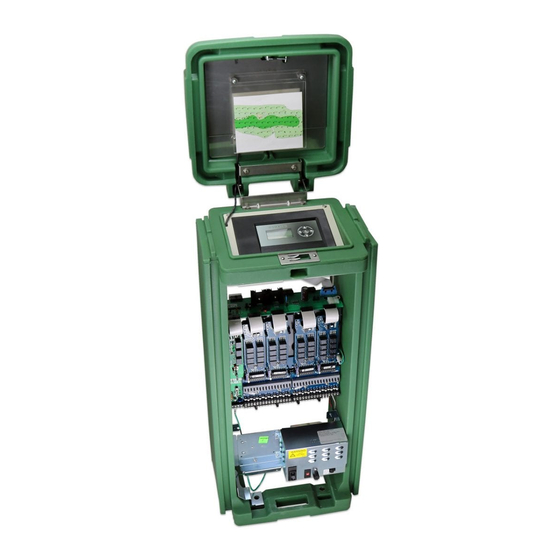
Introduction
The OSMAC G3 controller is designed for installation on a substantial concrete foundation with embedded conduit
of various diameters to enable power, field and earth ground wiring to be routed into the cabinet. A mounting bolt
positioner and basic mounting hardware components are included with each controller. Additional materials required to
complete the installation must be obtained separately. A material list can be compiled by reading through the instructions
completely prior to starting the installation.
CAUTION: For your protection and the safety of the product user, comply with all Caution and Warning Statements
within this document. All installation practices must comply with all applicable national and/or local electrical and
construction codes.
Foundation Construction
1.
Prepare a hole for the foundation
and wiring conduit using the
minimum recommended dimensions
shown in Figure 1.
*Note: Refer to local electrical
codes for required depth of buried
wiring.
2.
Trench to the foundation site as
required for each wiring run.
3.
Position the straight and sweep
elbow conduit sections in the
foundation hole as shown. Tape
the conduit ends to seal out dirt.
Backfill soil to form a 6" (15.2cm)
foundation depth. Conduit should
not extend more than 2" (51mm)
above the finished top surface of the
foundation.
4.
Prepare the sides of the foundation
hole with wood forms.
5.
Prepare the mounting bolt positioner
with the 5/16" x 4-1/2" bolts and
nuts (provided) as shown in Figure 1.
The threads should extend 2"
(51mm) from the top surface of the
bolt positioner.
6.
Pour concrete into the formed
foundation hole. Press the mounting
bolt positioner into the concrete
until it is flush and level with the
foundation surface and aligned with
the conduit.
7.
Finish the concrete with a level flat
area for the pedestal base (13" x
13" [33cm x 33cm] for the metal
cabinet or 16" x 16" [41cm x 41cm]
for the plastic cabinet). To prevent
pooling at the base of the pedestal,
add a slight taper away from the
cabinet base contact area. Allow the
concrete to sufficiently harden before
continuing.
8.
Remove the hex nuts from the
mounting bolts. Place the pedestal
on the pad ensuring all bolts pass
though the holes provided. Install a
flat washer and a hex nut on each bolt and tighten securely.
OSMAC
Installation Instructions
Figure 1
Wood Form
Plastic Cabinet Base Area
Metal Cabinet Base Area
Mounting Bolt Positioner
3" (76mm) Conduit - Field
(32 Stations Each)
3/4" (19mm) Conduit
Earth Ground
3/4" (19mm) Conduit
AC Power
2" (51mm) Max
6" (15.2cm)
Mounting Bolt
Positioner
Concrete
G3 Satellite
®
2"
(51mm)
Mounting Bolt w/ Hex Nuts
(Typical 4 Places)
30"
(76cm)
30"
(76cm)
Taper
See *Note
Advertisement
Table of Contents

Related Manuals for Toro OSMAC G3 Satellite


Summary of Contents for Toro OSMAC G3 Satellite
- Page 1 OSMAC G3 Satellite ® Installation Instructions Introduction The OSMAC G3 controller is designed for installation on a substantial concrete foundation with embedded conduit of various diameters to enable power, field and earth ground wiring to be routed into the cabinet. A mounting bolt positioner and basic mounting hardware components are included with each controller.
- Page 2 It is further recommended that all earth grounds and surge protection devices be checked yearly and after each lightning event. Toro advises against the use of a bonding/shielding wire in conjunction with Toro irrigation control systems. Grounding materials or equipment that are not specified in these instructions should not be connected to the Toro control products, Toro communication/power wiring or the grounding for the communication/power wiring.
-
Page 3: Field Wire Installation
Place the controller’s main power switch in the Off position. See Figure 3. Position the input voltage select switch to the 115V (for 115-120V service) or 230V (for 230-240V service) as required. Remove the power wiring access cover located on the back of the power supply assembly. See Figure 4. Note: The power and equipment ground wires are connected to a terminal block located on the back of the power supply assembly. - Page 4 Field Wire Installation (continued) Secure the field common wire(s) and Pump Power Single Controller Multiple Controllers pump start relay (or master valve) wire to Source the appropriate terminals on the Pump/ Magnetic To Other Com module. See Figure 6. Pump Controllers Starter Momentarily touch each valve control wire...
-
Page 5: Setting Time And Date
What’s Running Page Monitor Sig Radio Frequency Channel: 1 Manual Watering Page History Radio Information Scheduled Watering Radio Menu Radio Send Command Rx Freq1 462.2125MHz Communication Sat Address: 001 Promiscuous: No Tx Freq1 462.2125MHz a Diagnostics Comm Code: Central WMX Enable: Setting Receive Only Radio Reset Radio Defaults... - Page 6 Satellite Operations Using a Hand-Held Radio The following list of satellite operations can be initiated in the field using a hand-held radio keypad. All operation commands must begin with the following keypad sequence: * 9 followed by the 3-digit satellite address number. The command code is then entered, followed by additional digits which represent selected stations and/or run time values.
- Page 7 Command Code Operation Description 8006 01 Sets the syringe time in 30-second intervals; e.g., 8006 01 0100 (without a password) or 8006 pppp 01 0100 (with a password) sets the syringe time to 100 intervals (50 minutes). The number of intervals must be given as four digits with leading zeros but can be no greater than 0255. 8006 03 Enables/disables the password.
-
Page 8: Specifications
“How to Identify and Resolve Radio-TV Interference Problems.” This booklet is available from the U.S. Government Printing Office, Washington, DC 20402. Stock No. 004-000-00345-4. International: This is a CSPR 22 Class B product. © 2018 The Toro Company, Irrigation Business • www.toro.com Form Number 373-0889 Rev B...