Table of Contents

Related Manuals for LG MC-3182NBR


Summary of Contents for LG MC-3182NBR
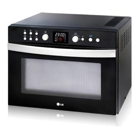
- Page 1 삼 흥 정 판 Internal Use Only Website http://biz.lgservice.com MICROWAVE OVEN SERVICE MANUAL MODEL: MC-3182NBR CAUTION BEFORE SERVICING THE UNIT, READ THE SAFETY PRECAUTIONS IN THIS MANUAL. October, 2008 P/NO : MFL34215511 Printed in Korea...
-
Page 2: Safety Precautions
SAFETY PRECAUTIONS This device is to be serviced only by properly qualified service personnel. Consult the service manual for proper service procedures to assure continued safety operation and for precautions to be taken to avoid possible exposure to excessive microwave energy. PRECAUTIONS TO BE OBSERVED BEFORE AND DURING SERVICING TO AVOID POSSIBLE EXPOSURE TO EXCESSIVE MICROWAVE ENERGY... -
Page 3: Table Of Contents
CONTENTS (Page) SAFETY PRECAUTIONS - - - - - - - - - - - - - - - - - - - - - - - - - - - - - - - - - - - - - - - - - - - - - - - - - - - - - - - - - - - - - - - - - - - - - Inside front cover SPECIFICATIONS - - - - - - - - - - - - - - - - - - - - - - - - - - - - - - - - - - - - - - - - - - - - - - - - - - - - - - - - - - - - - - - - - - - - - - - - - - - - - - - - - - - - - - - - - - - - - - - - - - - - - 1-1 CAUTIONS - - - - - - - - - - - - - - - - - - - - - - - - - - - - - - - - - - - - - - - - - - - - - - - - - - - - - - - - - - - - - - - - - - - - - - - - - - - - - - - - - - - - - - - - - - - - - - - - - - - - - - - - - - - - - - 2-1 INSTALLATIONS - - - - - - - - - - - - - - - - - - - - - - - - - - - - - - - - - - - - - - - - - - - - - - - - - - - - - - - - - - - - - - - - - - - - - - - - - - - - - - - - - - - - - - - - - - - - - - - - - - - - - - 3-1... -
Page 4: Specifications
SPECIFICATIONS ITEM DESCRIPTION MODEL MC-3182NBR Power Requirement 230 V~ 50 Hz Single phase, 3 wire grounded Microwave 1500W Grill 1250W Combination max. 3000W Convection max. 2650W Power Output 1000 watt full microwave power (IEC60705) Microwave Frequency 2450 MHz ± 50 MHz... -
Page 5: Cautions
CAUTIONS Unlike other appliances, the microwave oven is MICROWAVE RADIATION high-voltage and high-current equipment. Personnel should not be exposed to the Though it is free from danger in ordinary use, microwave energy which may radiate from the extreme care should be taken during repair. magnetron or other microwave generating device if it is improperly used or connection. -
Page 6: Installations
INSTALLATIONS BEFORE YOU BEGIN, READ THE FOLLOWING INSTRUCTIONS COMPLETELY AND CAREFULLY. INSTALLING EARTHING INSTRUCTIONS 1. Empty the microwave oven and clean inside it with This microwave oven is designed to be used in a fully a soft, damp cloth. Check for damage such as earthed condition. -
Page 7: Operating Instructions
OPERATING INSTRUCTIONS FEATURES Square tray Crisp tray Oven Front Plate Control Panel Window Door Screen Turn Table Low rack Square rack Shaft Choke Cover Glass tray Safety Door Lock System High rack CONTROL PANEL 1. Auto Cook: Auto cook allows you to cook most of 9. -
Page 8: Operating Sequence
OPERATING SEQUENCE The following is a description of component functions 8. EZ CLEAN during oven operation. Select Stop/Clear Start ez clean 1. SETTING THE CLOCK Select Stop/ Desired Press 7. AUTO DEFROST Clear power level Dial Micro Function Desired defrost Desired Stop/Clear Start... -
Page 9: Schematic Diagram
SCHEMATIC DIAGRAM... -
Page 10: Circuit Description
CIRCUIT DESCRIPTION GENERAL DETAILS WHEN THE DOOR IS OPENED DURING COOKING • The low voltage transformer supplies the necessary voltage to the micom controller when power cord is • Both the primary switch and relay 2 are cut off primary winding voltage of the high voltage transformer. -
Page 11: Service Information
SERVICE INFORMATION TOOLS AND MEASURING INSTRUMENTS NECESSARY TOOLS NECESSARY MEASURING INSTRUMENTS Tools normally used for TV servicing are sufficient. • TESTER(VOLTS-DC, AC., Ohmmeter) Standard tools are listed below. • Microwave survey meter • Diagonal pliers - Holaday HI-1500 • Long nose pliers HI-1501 •... - Page 12 MEASUREMENT WITH OUTER CASE NOTES WHEN MEASURING REMOVED • Do not exceed meter full scale deflection. • The test probe must be removed no faster than • When you replace the magnetron, measure for 1 inch/sec (2.5 cm/sec) along the shaded area, microwave energy leakage before the outer case is otherwise a false reading may result.
-
Page 13: Measurement Of Microwave Power Output
MEASUREMENT OF MICROWAVE POWER OUTPUT • Microwave power output measurement is made with • The microwave power output P in watts is calculated the microwave oven supplied at its rated voltage and from the following formula : operated at its maximum microwave power setting 4187 x (∆T) + 0.55 X (T )X M... - Page 14 E. DOOR ASSEMBLY / REMOVAL F. AIR DUCT ASSEMBLY REMOVAL 1) Open the door. 1) Disconnect the leadwire from lamp. 2) Remove the choke cover very carefully with a 2) Remove the mounting screw to the cavity. flat-blade screwdriver. CAUTION: Be careful not to damage door seal G.
- Page 15 H. FAN MOTOR ASSEMBLY / REMOVAL K. THE TURNTABLE MOTOR REMOVAL 1) Discharge the high voltage capacitor. 1) Remove the turntable. 2) Disconnect the leadwire from fan motor, noise filter 2) Remove the turntable shaft VERY CAREFULLY and high voltage capacitor. with a slotted screwdriver.
- Page 16 L. C-MOTOR AND SHEATH HEATER M. INTERLOCK SYSTEM REMOVAL 1) INTERLOCK MECHANISM The door lock mechanis m is a device which has 1) Remove the air guide and the air duct. been s pecially des igned to eliminate completely 2) Disconnect the leadwire from the circulation motor microwave activity when the door is opened during and the sheath heater.
-
Page 17: Interlock Continuity Test
INTERLOCK CONTINUITY TEST WARNING : FOR CONTINUED PROTECTION AGAINST EXCESSIVE RADIATION EMISSION, REPLACE ONLY WITH IDENTICAL REPLACEMENT PARTS. TYPE NO. SZM-V 16-FA-63 OR VP-533A-OF OR V-5230Q FOR PRIMARY SWITCH TYPE NO. SZM-V 16-FA-62 OR VP-532A-OF OR V-5220Q FOR MONITOR SWITCH TYPE NO. -
Page 18: Component Test Procedure
COMPONENT TEST PROCEDURE CAUTIONS 1. DISCONNECT THE POWER SUPPLY CORD FROM THE OUTLET WHENEVER REMOVING THE OUTER CASE FROM THE UNIT. PROCEED WITH THE TEST ONLY AFTER DISCHARGING THE HIGH VOLTAGE CAPACITOR AND REMOVING THE WIRE LEADS FROM THE PRIMARY WINDING OF THE HIGH VOLTAGE TRANSFORMER. - Page 19 COMPONENTS TEST PROCEDURE RESULTS Antenna Gasket Chassis Filament Terminals NOTE: When testing the magnetron, be sure to install the magnetron gasket in the correct position and be sure that the gasket is in good condition. HIGH VOLTAGE Measure the resistance. Normal: Momentarily indicates CAPACITOR (Ohm-meter scale: Rx1000)
- Page 20 COMPONENTS TEST PROCEDURE RESULTS FUSE Check for continuity of the fuse with an Normal Abnormal multi-meter. NOTE: If the fuse is blown, check the primary, the secondary, and the monitor switches, H.V.D. and H.V.C. before replacing the fuse. If the fuse is blown by improper switch operation replace the defective switch and the fuse at the same time.
- Page 21 COMPONENTS TEST PROCEDURE RESULTS Cooking Start Disconnect the 7 pin Check for P.C.B. connector. connector from P.C.B. (Refer to schemetic diagram) 1 2 3 4 5 6 7 Cooking Start RELAY 2, RELAY 3, RELAY 5 OF P.C.B. (Wire leads removed.) Relay 2 Relay 2: Microwave Relay 3: Grill...
- Page 22 COMPONENTS TEST PROCEDURE RESULTS Normal : COM-230V : Approx. 180 Ω CIRCULATION MOTOR (Wire leads removed) Abnormal : Infinite or several ohm. NOTE : A MICROWAVE ENERGY LEAKAGE TEST MUST ALWAYS BE PERFORMED WHEN THE UNIT IS SERVICED FOR ANY REASON. MAKE SURE THE WIRE LEADS ARE CORRECT POSITION.
-
Page 23: Trouble Shooting (Display Shows Error Mode)
TROUBLE SHOOTING WHEN YOU GET A COMPLAINT FROM YOUR CUSTOMER, EVALUATE THE COMPLAINT CAREFULLY. IF THE FOLLOWING SYMPTOMS APPLY, PLEASE INSTRUCT THE CUSTOMER IN THE PROPER USE OF THE MICROWAVE OVEN. THIS CAN ELIMINATE AN UNNECESSARY SERVICE CALL. CAUTIONS 1. Check grounding before checking for trouble. 2. - Page 24 (TROUBLE 1) The following visual conditions indicate a probable defective control circuit. 1. Incomplete segments. • Segment missing. • Partial segment missing. • Digit flickering (NOTE: Slight flickering is normal.) 2. Colon does not turn on or blink. 3. A distinct change in the brightness of one or more numbers in display. 4.
- Page 25 (TROUBLE 2) Oven does not operate at all ; Display window does not display any figures and no input is accepted. CONDITION CHECK RESULT CAUSE REMEDY Replace primary Malfunction of the Check continuity 1. Fuse blows. Continuity. and monitor monitor switch. of monitor switches.
- Page 26 (TROUBLE 3) Display shows all figures set, but oven does not start cooking while desired program times are set and START pad is touched. CONDITION CHECK RESULT CAUSE REMEDY Defective Replace Check continuity 1.Setting time does No continuity. secondary switch. secondary switch.
- Page 27 (TROUBLE 5) No microwave oscillation even though oven lamp and fan motor run (Display operates properly) CONDITION CHECK RESULT CAUSE REMEDY Defective P.C.B No microwave Disconnect the Replace P.C.B No continuity. oscillation. wire leads from assembly assembly relay 2 and check continuity Continuity.
- Page 28 (TROUBLE 6) Oven does not cook properly when programmed for the set power level (Operates properly on HIGH) CONDITION CHECK RESULT CAUSE REMEDY Output is full when Defective P.C.B. Replace P.C.B. Disconnect the Abnormal. you set lower assembly. assembly. wire leads from power level.
- Page 29 (TROUBLE 8) Display shows error mode CONDITION CHECK RESULT CAUSE REMEDY Display shows Connect them Check the No continuity Loose connection "E01" tightly connnection between thermistor and Continuity P.C.B. assembly Check the Defective thermistor Replace the Abnormal. thermistor (Thermistor shorted) thermistor Defective Replace the...
-
Page 30: Exploded View
#EV# EXPLODED VIEW INTRODUCTION MODEL: OVEN CAVITY PARTS INTERIOR PARTS BASE PLATE PARTS DOOR PARTS LATCH BOARD PARTS CONTROL PANEL PARTS MAY000 MFL552 MAX171 MEZ173 -6-1-... - Page 31 #EV# DOOR PARTS 13581A 13552A 14026A WTP005 13213A WSZ085 13551A 13650A WTP037 WNZ027 14810L 14810R 14270A -6-2-...
- Page 32 #EV# CONTROL PANEL PARTS 24781S 24810C WTT024 WTT024 WTP004 24980A WTP018 250202 268712 249401 23572A 23790D 268711 23550D 250201 -6-3-...
- Page 33 #EV# OVEN CAVITY PARTS WTT021 33112U 368771 34930R 33052M 36549S 33391M WTP013 63303A 35026A 63302A 35026G 35026C 647781 33390M WTT028 647781 WTT028 33390G 65238A 34370T 35889A WTT021 -6-4-...
- Page 34 #EV# LATCH BOARD PARTS WSZ236 WSZ236 43501L 43501R 466001 43500R 449701 466001 449701 44510A 43500L 44510A 449702 449702 466003 -6-5-...
- Page 35 #EV# INTERIOR PARTS 33809A WTT021 568772 WNH002 548101 56930M WTT021 53052M 55012A 559003 565491 WSZ232 565492 54810H 55300S 559001 559002 WTT021 54350S WNH200 548102 559004 552384 WSZ232 WNH003 535042 54620A 535041 548103 WWS005 WTT021 WSZ185 54810H WSZ062 56411A 568771 -6-6-...
- Page 36 #EV# INSULATOR PARTS WSZ002 WSZ002 56851C 54810C 55262A WTT021 56549S 466002 50CZZH WTP007 WTP013 WTT021 36549W WTT030 552382 54811A 54810U 33550V 552385 WTT021 WTT028 WTT021 36549V 34930W WSZ002 56930V WTT021 WTT021 552381 348102 WTT021 56170D WTT021 WTT021 552383 348101 35012A 54980N 50FZZ1 56912B...