Motorola APX 2000 User Manual
Hide thumbs
Also See for APX 2000:
- User manual (206 pages) ,
- Quick reference manual (47 pages) ,
- Quick reference card (2 pages)
Table of Contents
Advertisement
Quick Links
Advertisement
Table of Contents

Related Manuals for Motorola APX 2000


Summary of Contents for Motorola APX 2000
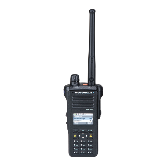
- Page 1 APX™ TWO-WAY RADIOS APX 2000 MODEL 1 USER GUIDE APX 2000...
- Page 3 MOTOROLA, MOTO, MOTOROLA SOLUTIONS and the Stylized M logo are trademarks or registered trademarks of Motorola Trademark Holdings, LLC and are used under license. All other trademarks are the property of their respective owners. © 2012–2013 by Motorola Solutions, Inc. All Rights Reserved. 11/13 English 1303 East Algonquin Road, Schaumburg, Illinois 60196, U.S.A.
- Page 4 Sending an Emergency Call Display Status Icons On = User is currently associated with the radio. Press the Emergency button. Receiving a call or data Off = User is currently not associated with the radio. Press and hold the PTT button. Speak clearly Transmitting a call or data Blinking = Device registration or user into the microphone.
-
Page 5: Table Of Contents
Contents Documentation Copyrights...13 Disclaimer........14 Declaration of Conformity......6 Important Safety Information..8 Getting Started....... 15 How to Use This Guide........15 Notations Used in This Manual......15 Software Version......9 Additional Performance Enhancement..15 Notice to Users (FCC and Industry Dynamic System Resilience (DSR)..15 Canada)............9 CrossTalk Prevention......15 Conventional Talkgroup and Radio... - Page 6 Attaching the Belt Clip........20 Turning On the Radio........20 General Radio Operation....38 Adjusting the Volume........21 Selecting a Zone..........38 Selecting a Radio Channel......38 Identifying Radio Controls.... 23 Mode Select Feature........39 Radio Parts and Controls.......23 Saving a Zone and a Channel to a Programmable Features........
- Page 7 Selective Call (ASTRO Fireground (Conventional Only).....52 Conventional Only)......44 Entering Fireground Zone Channel..53 Responding to the Dynamic Responding to Evacuation Indicator... 53 Regrouping Feature (Trunking Automatic Registration Service (ARS)...54 Only)..........44 Selecting or Changing the ARS Scan Lists............45 Mode..........54 Viewing a Scan List......46 Secure Operations.........55 Viewing and Changing the Priority...
- Page 8 Transmit Inhibit........67 Glossary..........77 Helpful Tips........69 Radio Care.............69 Limited Warranty......82 Cleaning Your Radio......69 MOTOROLA COMMUNICATION Proper Ways to Handle the Radio..70 PRODUCTS..........82 Radio Service and Repair....70 I. WHAT THIS WARRANTY COVERS Battery Care...........70 AND FOR HOW LONG:......82 Battery Charge Status......70...
- Page 9 VI. PATENT AND SOFTWARE PROVISIONS:.......... 84 VII. GOVERNING LAW:.........86 VIII. For Australia Only:........86 English...
-
Page 10: Declaration Of Conformity
Name: Motorola Solutions, Inc. Address: 1303 East Algonquin Road, Schaumburg, IL 60196-1078, U.S.A. Phone Number: 1-800-927-2744 Hereby declares that the product: Model Name: APX 2000 conforms to the following regulations: FCC Part 15, subpart B, section 15.107(a), 15.107(d) and section 15.109(a) English... - Page 11 Class B Digital Device As a personal computer peripheral, this device complies with Part 15 of the FCC Rules. This device complies with Industry Canada licence-exempt RSS standard(s). Operation is subject to the following two conditions: 1 This device may not cause harmful interference, and 2 This device must accept any interference received, including interference that may cause undesired operation.
-
Page 12: Important Safety Information
Radios which contains important operating instructions for safe usage and RF energy awareness and control for Compliance with applicable standards and Regulations. For a list of Motorola-approved antennas, batteries, and other accessories, visit the following website: http://www.motorolasolutions.com/APX Under Industry Canada regulations, this radio... -
Page 13: Software Version
This device may not cause harmful interference. • This device must accept any interference received, including interference that may cause undesired operation. • Changes or modifications made to this device, not expressly approved by Motorola, could void the user's authority to operate this equipment. English... -
Page 14: Consignes De Sécurité Importantes
Cet émetteur radio a été approuvé par Industrie Canada pour utilisation avec une antenne approuvée Cette radio ne doit être utilisée qu'à des fins par Motorola offrant le gain maximal autorisé et professionnelles. Avant d'utiliser la radio, lisez le l'impédance requise pour le type d'antenne indiqué. Il... -
Page 15: Version Logicielle
Motorola, peuvent annuler le droit de l'utilisateur à Version logicielle utiliser cet équipement. Toutes les fonctions décrites dans les sections suivantes sont prises en charge par la version R13.00.00 ou les versions ultérieures du logiciel de la radio. Pour obtenir davantage de renseignements à propos des fonctions prises en charge, adressez-vous à... -
Page 16: Computer Software Copyrights
Motorola. Furthermore, the purchase of Motorola products shall not be deemed to grant either directly or by implication, estoppel, or otherwise, any license under the copyrights, patents or patent... -
Page 17: Documentation Copyrights
No duplication or distribution of this document or any portion thereof shall take place without the express written permission of Motorola. No part of this manual may be reproduced, distributed, or transmitted in any form or by any means, electronic or mechanical, for any purpose without the express written permission of Motorola. -
Page 18: Disclaimer
However, no responsibility is assumed for inaccuracies. Furthermore, Motorola reserves the right to make changes to any products herein to improve readability, function, or design. Motorola does not assume any liability arising out of the applications or use of any product or circuit described herein;... -
Page 19: Getting Started
damage to the equipment if not carefully Getting Started observed. Note: An operational procedure, practice, or condition How to Use This Guide and so on, which is essential to emphasize. This User Guide covers the basic operation of the Additional Performance Enhancement APX Portables. -
Page 20: Conventional Talkgroup And Radio Scan Enhancements
varied from the Receiving Frequency. This Smart PTT is supported with this enhancement as subsequently reduced the possibilities of radio Smart PTT prevents users from transmitting while frequency interfering spurs and prevents the issues of other users are on the channel. crosstalk. -
Page 21: Preparing Your Radio For Use
Accessories on page Note: When charging a battery attached to a radio, turn the radio off to ensure a full charge. To charge the battery, place the battery (with or without the radio), in a Motorola-approved charger. English... -
Page 22: Attaching The Antenna
2 To remove the battery, lift up the latch ( ) which is 1 Set the antenna in its receptacle. at the bottom of the radio, then slide the battery 2 Turn the antenna clockwise to attach to the radio. out from the radio. -
Page 23: Removing And Attaching The Accessory Connector Cover
Removing and Attaching the Accessory Connector Cover The accessory connector is located on the antenna side of the radio. It is used to connect accessories to the radio. Note: To prevent damage to the connector, shield it with the connector cover when not in use. 1 To remove the accessory connector cover, rotate the thumbscrew counterclockwise until it... -
Page 24: Attaching The Belt Clip
Attaching the Belt Clip 1 Align the grooves of the belt clip with those of the radio and push down until you hear a click. Turning On the Radio 1 Press the Multi-Function Knob until the radio display lights on, then release the knob. 2 To remove the clip, use a flatbladed object to press the belt clip tab ( ) away from the radio. -
Page 25: Adjusting The Volume
Power off?, press the Menu Select button below Yes to power off. Adjusting the Volume Ensure the radio is power on and the main speaker is pointed towards you for increased loudness and intelligibility, especially in areas with loud background noises. - Page 26 2 To decrease the volume, rotate this knob counterclockwise. The display shows volume bars and volume level when you change the volume. English...
-
Page 27: Identifying Radio Controls
Identifying Radio Controls Radio Parts and Controls Multi- Function Knob (MFK) Top Lightbar Microphone Top Side (Select) Button Push-to-Talk (PTT) Button Side Button 1 English... -
Page 28: Programmable Features
using the radio's programming software, in order to Side Button 2 assign a feature to that control. Menu Select Buttons The programmable buttons can be programmed as Main Display shortcuts to radio functions or preset channels/groups depending on the duration of a button press: Speaker Press Pressing and releasing rapidly. - Page 29 Dynamic Priority Allows any channel in a Scan designated transmit channel (Conventional List (except for the Priority-One from the scan list. Only) channel) to temporarily replace One Touch 1– 4 Launches a specific feature the Priority-Two channel. with one single button-press. Emergency Depending on the You can setup as many as four...
-
Page 30: Assignable Settings Or Utility Functions
Assignable Settings or Utility Functions Scan List Selects the scan list for editing Programming (by long press on the Scan Keypad/Controls Locks or unlocks the keypad, button). Lock programmable buttons, switches or rotary knobs. Secure Toggles the Secure Transmission Transmission On or Off when Light/Flip Press the button to toggle the Select... -
Page 31: Menu Select Buttons
Multi-Function Knob (MFK) • Use the Menu Select Button. MFK is the on/off button of your radio. See Turning • Use the Menu Select buttons below the softkeys. On the Radio on page 20 for the procedure to power up and down the radio. In addition, there are programmable features available for MFK. -
Page 32: Push-To-Talk (Ptt) Button
The radio by default is set to use the primary feature. Push-To-Talk (PTT) Button Short presses of MFK toggle it to work on either the secondary or primary feature. The main display only shows the icon of secondary feature; the main display does not show the icon of primary feature. -
Page 33: Identifying Status Indicators
Received Signal Strength Indicator Identifying Status Indicators (RSSI) Status Icons The number of bars displayed represents the received signal strength The 160 x 90 pixel front liquid crystal display (LCD) of for the current site, for trunking only. The your radio shows radio status, text entries, and menu more stripes in the icon, the stronger the entries. - Page 34 In-Call User Alert Vote Scan Enabled On– The feature is enabled. Voice The vote scan feature is enabled. muting of the affiliated trunking talkgroup or selected conventional channel is Secure Operation activated. Secure operation. Off– The feature is disabled. Voice Clear operation.
-
Page 35: Led Indicator
Blinking– Device registration or user registration with the server failed due to an invalid username or pin. Inverted– User successfully login to the secured IP Packet Data. Data Activity Data activity is present. MFK is in Mode Change feature Turn the MFK to change the channel/ zone. -
Page 36: Top Lightbar Indicator
Solid yellow Channel is busy. Top Lightbar Indicator (Conventional Only) Blinking yellow Radio is receiving a secured transmission. Solid green Radio is powering up, or is on a non-priority channel while in the Scan List Programming mode. Blinking green Radio is receiving an individual or telephone call, or is on a Priority-Two channel while in the Scan List Programming... -
Page 37: Intelligent Lighting Indicators
Intelligent Lighting Indicators This feature temporarily changes the color of the Top Lightbar and adds a color bar to the main display screen to help signal that a radio event has occurred. Note: This feature must be preprogrammed by a qualified radio technician. Backlight and Bar Notification When... -
Page 38: Alert Tones
Backlight and Bar Notification When Color The radio receives a selective call. The radio enters Geofence. Alert Tones Your radio uses alert tones to inform you of your radio’s condition. The following table lists these tones and when they occur. You Hear Tone Name Heard... - Page 39 You Hear Tone Name Heard Lack of Voice PTT Time out When the radio ends your call after it detected there are lack of voice for 5 seconds after the PTT is pressed and hold. Your radio ends the call to enable your radio to receive calls from other radio users.
- Page 40 You Hear Tone Name Heard Emergency Exit When exiting the emergency state. A Group of Failsoft When the trunking system fails. Medium- Automatic Call Back When voice channel is available from previous request. Pitched Tones Keyfail When encryption key has been lost. Console Acknowledge When status, emergency alarm, or reprogram request ACK is received.
-
Page 41: Phone Call Displays And Alerts
You Hear Tone Name Heard Unique Low- MFK Enters Secondary When MFK is toggled to enter Secondary Feature High Tone Feature Unique High- MFK Exits Secondary When MFK is toggled to exit secondary feature and return to Low Tone Feature primary feature. -
Page 42: General Radio Operation
b) Press the PTT button to transmit on the General Radio Operation displayed zone channel. Selecting a Zone Selecting a Radio Channel Your radio must be preprogrammed to allow you to A channel is a group of radio characteristics, such as use this feature. -
Page 43: Mode Select Feature
Positions of ChUp and ChDn on the display may 1 Toggle your zone and channel to the required differ each time you release the Menu Select zone and channel. button. Read carefully before you press. 2 Press and hold the Menu Select button directly b) Press the PTT button to transmit on the displayed zone and channel. -
Page 44: Receiving And Responding To A Radio Call
Note: Repeat this procedure to change the zone and When you receive a talkgroup call (while on the channel of the programmed button. Short press of the Home screen) the radio triggers for your attention with programmed button one of the following scenarios depending on the system your radio is configured: Short press of the programmed button changes your current transmission to the zone and channel... -
Page 45: Receiving And Responding To A Telephone Call (Trunking Only)
receiving radio is active on the system and can 3 Press or the Call Response button to hang up display the caller ID. and return to the Home screen. Note: With the inactivity timer enabled (optional), You cannot initiate a Private Call. when there is no response from the receiving radio, the transmitting radio exits the call with Menu Inactive Receiving and Responding to a Telephone Call... -
Page 46: Switching Between Repeater Or Direct Operation Button
You cannot initiate a Telephone Call. Monitor Feature Switching Between Repeater or Direct Radio users who switch from analog to digital radios Operation Button often assume that the lack of static on a digital channel is an indication that the radio is not working The Repeater Operation increases the radio’s range properly. -
Page 47: Monitoring Conventional Mode
The Carrier Squelch indicator appears on the 3 Press the Monitor button again, or the PTT display when you monitor a channel via the button, to return to the original squelch setting. preprogrammed Monitor button. If you try to transmit on a receive-only channel, you hear an invalid tone until you release the PTT •... -
Page 48: Advanced Features
Responding to the Dynamic Regrouping Feature Advanced Features (Trunking Only) This feature allows the dispatcher to temporarily Advanced Call Features reassign selected radios to a particular channel where they can communicate with each other. This Selective Call (ASTRO Conventional Only) feature is typically used during special operations and is enabled by a qualified radio technician. -
Page 49: Scan Lists
that you were using before the radio was dynamically Select Select-enabled radios are free to regrouped. Enabled change to any available channel, Requesting a Reprogram (Trunking Only) including the dynamic-regrouping channel, once the user has selected This feature allows you to notify the dispatcher when the dynamic-regrouping position. -
Page 50: Viewing A Scan List
Please refer to a qualified radio technician for the • A Scan icon indicates that the current channel maximum number of Scan Lists can be programmed is in the scan list as a non-priority channel. The in your radio. These lists must be preprogrammed by LED lights up solid green. -
Page 51: Making A Dynamic Priority Change (Conventional Scan Only)
• Press the preprogrammed Scan button to a) When the radio locks onto the channel toggle Scan On or Scan Off to initiate or stop designated as the new Priority-Two channel, press the preprogrammed Dynamic Priority scan. button. • Press the Menu Select button directly below The radio continues scanning the remaining Scan. -
Page 52: Restoring A Nuisance Channel
The radio continues scanning the remaining channels call received icons blinks and the display shows Page in the list. received. Restoring a Nuisance Channel Press any button to clear the Call Alert page. To restore the deleted nuisance channel, perform You cannot send a Call Alert page. -
Page 53: Sending An Emergency Alarm
Note: To exit emergency at any time, press and hold Note: Emergency button press timer by default is set the preprogrammed Emergency button for about a to 1 second. This timer is programmable from 0 – 6 second. seconds by a qualified technician. The radio operates in the normal dispatch manner Press the preprogrammed Emergency button. -
Page 54: Sending An Emergency Call (Trunking Only)
Sending an Emergency Call (Trunking Only) 5 To exit Emergency Call, press and hold the preprogrammed Emergency button for about a This feature gives your radio priority access to a second. talkgroup. Sending an Emergency Alarm with Emergency Call 1 Press the preprogrammed Emergency button. One of the following scenarios will occur: This feature gives your radio priority access on a channel for conventional system, and to a talkgroup... -
Page 55: Sending A Silent Emergency Alarm
If unsuccessful, you hear the radio sounds a short The display shows no changes, the LED does not low-pitched tone to indicate the selected channel light up, and you hear no tones. The silent does not support emergency and rejects to launch emergency state continues until you perform the emergency mode. -
Page 56: Emergency Keep-Alive Feature
Emergency Keep-Alive Feature These components provide on-scene and inbuilding radio coverage, and enhanced personnel This feature, when enabled, prevents the radio from accountability and monitoring. being turned off via the MFK when the radio is in the Emergency state. The radio helps to indicate your presence on the scene if it is in the range of the Incident Commander Note: The radio only exits the Emergency state using command terminal. -
Page 57: Entering Fireground Zone Channel
• Sending an Emergency Alarm and Call • If your radio is working in Fireground Zone Channel, proceed to next step. Entering Fireground Zone Channel 4 Press and hold the PTT button to transmit. The 1 Upon powering up, perform one of the following LED lights up solid red while transmitting. -
Page 58: Automatic Registration Service (Ars)
• If preprogrammed with Manual Selecting or Changing the ARS Mode Acknowledgement of Evacuation Command, The following methods are options on how to select pressing the PTT button shall cancel the or change the ARS Mode. The result of all the indications and acknowledge the command methods is the same. -
Page 59: Secure Operations
The radio will not transmit until you set the trunked and conventional channels. Secure/ Clear switch to the secure position. Unlike other forms of security, Motorola digital The radio can be configured to ignore the clear encryption provides signaling that makes it virtually... - Page 60 2 Select the required keys and press the Menu Trunked If you use your radio for both Multikey conventional and trunked Select button directly below LOAD on the KVL. This loads the encryption keys into your radio. applications, you have to strap your encryption keys for trunking on a When the key has been loaded successfully, one of per-talkgroup or announcement-...
-
Page 61: Trunking System Controls
Note: Do not press the Top (Orange) button remains the same at before pressing the Top Side (Select) button, receiving radio. unless you are in an emergency situation as this sends an emergency alarm. Random FM Reduces the unwanted effects of Noise Hear Clear random FM noise pulses caused by... -
Page 62: Out-Of-Range Radio
predetermined frequency. You hear a medium- Site Trunking Feature pitched tone and the display shows Failsoft. If the zone controller loses communication with any When the trunking system returns to normal site, that site reverts to site trunking. operation, your radio automatically leaves failsoft The display shows the currently selected zone/ operation and returns to trunked operation. -
Page 63: Site Display And Search Button
• To lock the site, press the Menu Select button Changing the Current Site directly below Lock. The display shows Site Perform one of the following actions: locked. • To unlock the site, press the Menu Select • Press and hold down the preprogrammed Site button directly below Unlk. -
Page 64: Responding To The Notification Of Upgrade
delay changes to be installed on the radio when it is If the upgrade fails, the display shows Program being powered up. failed. The radio remains in current configuration. Note: This feature must be preprogrammed by a • If you choose to delay, the radio prompts to qualified radio technician. -
Page 65: Site Selectable Alerts (Astro 25)
Check with your agent if Voice Announcement is • Change to a new zone. The radio announces the available for the feature you need. current zone and channel it is transmitting. • Change to a new channel remaining within the The two options of priority for the Voice current zone. -
Page 66: Utilities
When mixing SSA with received voice audio, the SSA The following methods are options on how to select alert is reduced in volume to ensure that the voice the power level. The result of all the methods is the message is still heard clearly. Therefore, it is same. -
Page 67: Controlling The Display Backlight
Locking and Unlocking the Controls The display shows momentary Radio ID off, and the radio alias disappears from the Home screen or You can lock your radio’s programmable buttons and the display shows momentary Radio ID on, and the MFK to avoid inadvertent entry. Check with your radio alias appears on the Home screen. -
Page 68: Turning Voice Mute On Or Off
Using the Time-Out Timer The display shows momentary Tones off, indicating that the tones are disabled or the This feature turns off your radio’s transmitter. You display shows momentary Tones on, and you cannot transmit longer than the preset timer setting. hear a short tone indicating that the tones are enabled. -
Page 69: Using Conventional Squelch Operation Features
Using Conventional Squelch Operation Features Option Result This feature filters out unwanted calls with low signal Normal Squelch You hear any digital strength or channels that have a higher than normal traffic having the correct background noise. network access code. Analog Options Selective Switch You hear any digital... -
Page 70: Digital Ptt Id Support
Digital PTT ID Support The following table shows the variations of smart PTT: This feature allows you to see the radio ID (number) of the radio from whom you are currently receiving a Mode Description transmission. This ID, consisting up to a maximum of Transmit Inhibit You cannot transmit if any traffic eight characters, can be viewed by both the receiving... -
Page 71: Transmit Inhibit
When the Transmit Inhibit feature is disabled, the 1 Perform one of the following actions: radio functions according to its normal operations. • Press the preprogrammed IP button. The radio sounds alert tone when user enters or exits • Press the Menu Select button directly below this feature and also when PTT is pressed. - Page 72 Disabling Transmit Inhibition Press the Transmit Inhibit programmable button. • or to TxIn. Press the Menu Select button below TxIn. Note: If the user has disabled TX Inhibit via the softkey and then moves the switch to the position where TX Inhibit is enabled, the new value overwrites the menu value.
-
Page 73: Helpful Tips
maintenance should be performed only by Helpful Tips a qualified radio technician. Cleaning Your Radio Radio Care Caution: Do not use solvents to clean your Caution: radio as most chemicals may permanently damage the radio housing and textures. • Your radio casting has a vent port that allows for pressure equalization in the Do not submerge the radio in the detergent radio. -
Page 74: Proper Ways To Handle The Radio
Proper Ways to Handle the Radio on a contract basis. For a contract service agreement, please contact your nearest Motorola service or sales • Do not pound, drop, or throw the radio representative, or an authorized Motorola dealer. unnecessarily. Never carry the radio by the antenna. -
Page 75: Battery Recycling And Disposal
Battery Recycling and Disposal Gauge Battery Charge In the U.S. and Canada, Motorola participates in the 76% to 100% full* nationwide Rechargeable Battery Recycling Corporation (RBRC) program for battery collection and recycling. Many retailers and dealers participate in this program. -
Page 76: Accessories
Accessories The accessory link below is for APX radios. Not all accessories are FCC certified to operate with all APX models and/or bandsplits. Please refer to the specific APX radio price pages for a list of FCC certified accessories or contact your sales representative for accessory compatibility. -
Page 77: Maritime Radio Use In The Vhf Frequency Range
• distance to a well-known landmark Maritime Radio Use in the VHF • vessel course, speed or destination Frequency Range 5 State the nature of the distress. 6 Specify what kind of assistance you need. Special Channel Assignments 7 State the number of persons on board and the number needing medical attention, if any. - Page 78 • on ships subject to the Safety Convention, the 156.100 160.700 radio must be capable of operating: 156.150 160.750 • in the simplex mode on the ship station 156.200 160.800 transmitting frequencies specified in the 156.025 – 157.425 MHz frequency band, and 156.250 160.850 •...
- Page 79 156.950 161.550 67** 156.375 156.375 157.000 161.600 156.425 156.425 157.050 161.650 156.475 156.475 157.100 161.700 156.575 156.575 157.150 161.750 156.625 – 157.200 161.800 156.675 156.675 157.250 161.850 156.725 156.725 157.300 161.950 157.350 161.950 157.400 162.000 77** 156.875 – 156.025 160.625 156.925 161.525 156.075...
-
Page 80: Declaration Of Compliance For The Use Of Distress And Safety Frequencies
157.275 161.875 Technical Parameters for Interfacing External Data Sources 157.325 161.925 157.375 161.975 RS232 SB9600 157.425 162.025 Input 3.6V Voltage Note: (Volts Peak-to- * Simplex channels 3, 21, 23, 61, 64, 81, 82, and 83 peak) cannot be lawfully used by the general public in US waters. -
Page 81: Glossary
Automatic Registration Service to it. It monitors and directs the operations of the trunked ASTRO 25 Motorola standard for wireless repeaters. digital trunked communications. Channel A group of characteristics such ASTRO... - Page 82 Conventional Typically refers to radio-to- even though the central radio communications, controller has failed. Each sometimes through a repeater trunked repeater in the system (see Trunking). transmits a data word informing every radio that the system has Conventional A scan list that includes only gone into failsoft.
- Page 83 Monitor Check channel activity by Page A one-way alert, with audio pressing the Monitor button. If and/or display messages. the channel is clear, you hear Personality A set of unique features static. If the channel is in use, specific to a radio. you hear conversation.
- Page 84 (send) operation when Standby An operating condition whereby pressed. the radio’s speaker is muted but still continues to receive Radio Frequency The part of the general data. (RF) frequency spectrum between the audio and infrared light Tactical/ Non- The user talks on the channel regions (about 10 kHz to Revert that was selected before the...
- Page 85 Zone A grouping of channels. English...
-
Page 86: Limited Warranty
MOTOROLA, at its option, will at no charge either Limited Warranty repair the Product (with new or reconditioned parts), replace it (with a new or reconditioned Product), or MOTOROLA COMMUNICATION PRODUCTS refund the purchase price of the Product during the warranty period provided it is returned in accordance with the terms of this warranty. -
Page 87: Ii. General Provisions
Because each FULL EXTENT SUCH MAY BE DISCLAIMED BY system which may use the Product is unique, LAW. MOTOROLA disclaims liability for range, coverage, or III. STATE LAW RIGHTS: operation of the system as a whole under this warranty. -
Page 88: What This Warranty Does Not Cover
MOTOROLA's normal warranty VI. PATENT AND SOFTWARE PROVISIONS: inspection and testing of the Product to verify any warranty claim. MOTOROLA will defend, at its own expense, any suit brought against the end user purchaser to the extent English... - Page 89 Product or parts MOTOROLA will have no liability with respect to any infringe a United States patent, and MOTOROLA will claim of patent infringement which is based upon the pay those costs and damages finally awarded against...
- Page 90 This Warranty is governed by the laws of the State of Illinois, U.S.A. VIII. For Australia Only: This warranty is given by Motorola Solutions Australia Pty Limited (ABN 16 004 742 312) of Tally Ho Business Park, 10 Wesley Court. Burwood East, Victoria.
- Page 92 Schaumburg, Illinois 60196 U.S.A. MOTOROLA, MOTO, MOTOROLA SOLUTIONS and the Stylized M logo are trademarks or registered trademarks of Motorola Trademark Holdings, LLC and are used under license. All other trademarks are the property of their respective owners. © 2012–2014 Motorola Solutions, Inc. All rights reserved.