Siemens C75 Service Manual
Hide thumbs
Also See for C75:
- User manual (161 pages) ,
- Operating manual (72 pages) ,
- Service repair documentation (37 pages)

Related Manuals for Siemens C75


Summary of Contents for Siemens C75
- Page 1 Local Service Organization Service Manual BE INSPIRED V1.0 Version Date Department Notes to change 08.08.2005 ICM MP CCQ SLI RHQ New Document Our innovation shapes the future...
-
Page 2: Table Of Contents
C75 Level 2 Service Manual Table of Contents GPRS (GENERAL PACKET RADIO SERVICE)………………………………….3 K JAVA APPLICATION……………………………………………………………….4 KEY FEATURES………………………………………………………………...…….5 COMPARISON WITH PERVIOUS PRODUCT...……………………...……………7 ACCESSORIES……………………………………………………….…………..8 UNIT DESCRIPTION C75..………..……………………………………………...….10 DISASSEMBLY OF C75..………………………………………………...……….12 REASSEMBLY OF C75..…..…………………………………………...……………19 ASSEMBLING AND DISASSEMBLING OF CAMERA MODULE……….………21 MOBILE SOFTWARE PROGRAMMING…………………………………………...23... -
Page 3: Gprs (General Packet Radio Service)
C75 Level 2 Service Manual GPRS (General Packet Radio Service) GPRS is a new non-voice value added services that allows information to be sent and received across a GSM mobile telephone network. It supplements today’s Circuit Switched Data (CSD) and Short Message Services (SMS). -
Page 4: Java Application
C75 Level 2 Service Manual K-Java Application Java-based game system Java Application Manager Application launcher (JAM) download manager. Supports HTTP-based download of applications over GPRS and CSD. RAM for Java applications Available Java applications (i.e. Program code and data) during application... -
Page 5: Key Features
C75 Level 2 Service Manual Key Features • Triple Band E-GSM 900 / GSM 1800 / GSM 1900 Bands • GPRS Multi Class 10 • Li-Ion Battery Pack Battery • Nominal Voltage : 3.7V • Nominal Capacity : 780 mAh •... - Page 6 C75 Level 2 Service Manual Acoustics • Three-in-one-earpiece for handset, handsfree and ringing tones • Omni-directional microphone • Loud signal emitter (soundringer) (>100dB(A) SPL @5cm, 'Hongkong-Spec.') only for rectangular sound signals (NOT POSSIBLE for all Soundringer melodies) • Polyphonic ringer tones (parallel to GPRS: 16 voices; all other Use Cases: 32 voices) •...
-
Page 7: Comparison With Pervious Product
C75 Level 2 Service Manual Comparison with Previous Product Feature R65/R66 Ulysses C75 ARIES Difference Supported Systems Triple Band Triple Band No NAFTA version EGSM 900/GSM1800/ EGSM 900/GSM1800/ planned GSM1900 (EMEA, GSM1900 (EMEA, APAC) APAC) GSM 850/GSM1800/ GSM1900 (NAFTA) Stand-by Time ≥... -
Page 8: Accessories
C75 Level 2 Service Manual Accessories For C75, the following accessories will be available. Description Part number Tour Case FCT-650 Belt Case FCL-600 Leather Case FCL-610 Li-Ion Battery 750mAh EBA-660 L36880-N7101-A111 Travel Charger ETC-500 L36880-N5601-A104 Travel Charger ETC-510 L36880-N5601-A105 Car Charger Plus ECC-600... - Page 9 C75 Level 2 Service Manual 5.1 C75 Interface to Accessories The phone has got a full compatible interface to accessories. The I/O-Connector (Lumberg-(slim)-connector) and RF-Connector will be in the same position as in the R65 X-Cite (and also R65 Penelope), target is that the two (three) phones can be used with the same accessories.
-
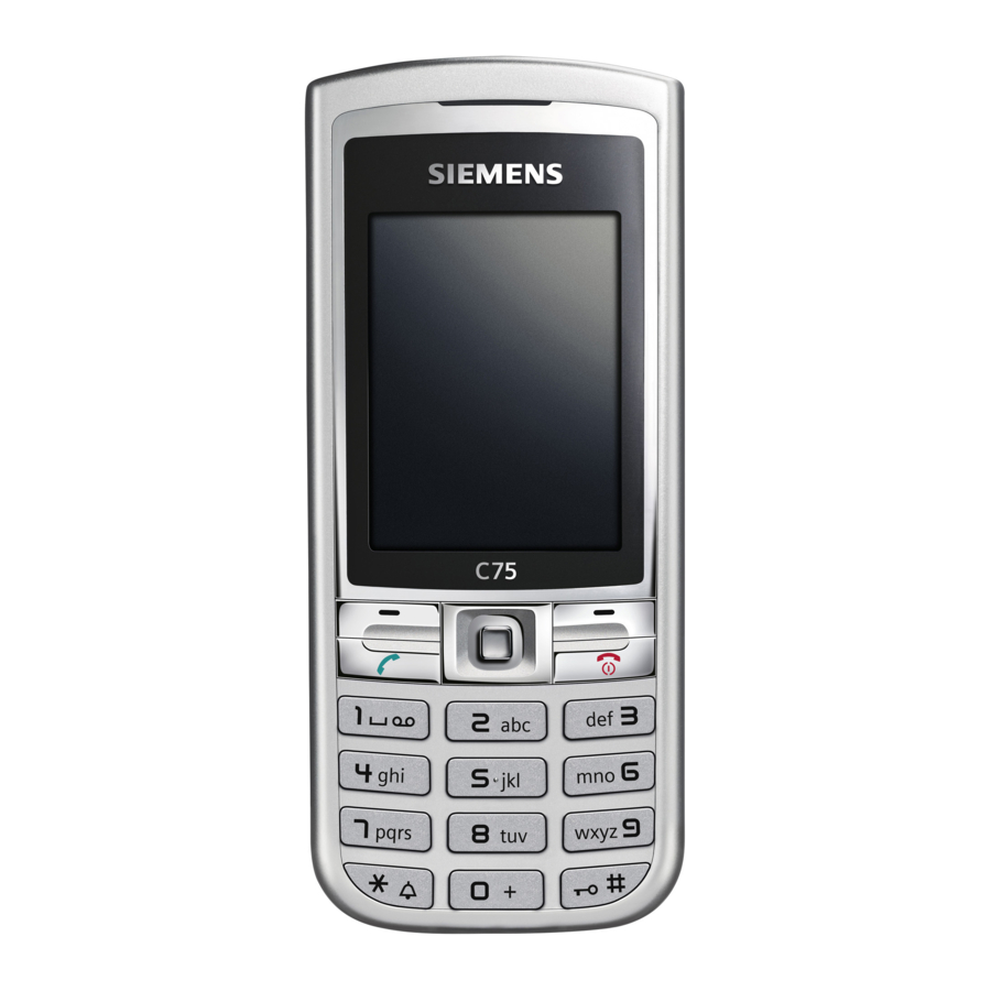
Page 10: Unit Description C75
C75 Level 2 Service Manual Unit Description of C75 The C75 ARIES is designed as a two-PCB bar phone. The lower case is an unlacquered plastic-part, the upper case as well as the battery-cover are lacquered plastic-parts (1- shot-moulding; 2 colours / see C75 ARIES M1 Product Contract for colour variants). - Page 11 C75 Level 2 Service Manual 6.1 Exploded View of C75 Upper Case Shell Light silver C39158-A160-A1 Keypad latin Light silver C39158-A160-A600 Screw 1,6x5,8 C39158-A84-C94 Joystick cap light silver C39158-A160-B650 MMI Board with S30880-Q6970-N2 Displaymodule V24851-Z1508-A130 Earphone V39104-F3090-X912 Swapboard S30880-Q6970-A10 Camera Module...
-
Page 12: Disassembly Of C75
C75 Level 2 Service Manual Disassembly of C75 ESD concept; the internal circuits will be more susceptible to ESD because of Note: the use of exchangeable housing. The construction of the internal block must be/is designed, in the best possible way, to protect the circuit against sparks. - Page 13 C75 Level 2 Service Manual Step 4 Remove Battery. Step 5 Remove SIM card. Copyright © Siemens Pte Ltd. Siemens Technical Support Centre All Rights Reserved COM D CCQ APAC SLI Page 13 of 40 Internal Use Only...
- Page 14 C75 Level 2 Service Manual Step 6 Unscrew the 6 T5 plus screws using a Torque screw driver. Step 7 Remove Lower Mounting Frame. Step 8 Remove Vibramotor. Copyright © Siemens Pte Ltd. Siemens Technical Support Centre All Rights Reserved...
- Page 15 C75 Level 2 Service Manual Step 9 Remove Microphone. Step 10 Remove Main Board. Step 11 Remove Display Module – Place protective foil over on the Display Module. Copyright © Siemens Pte Ltd. Siemens Technical Support Centre All Rights Reserved...
- Page 16 C75 Level 2 Service Manual Step 12 Remove Joystick Cap. Step 13 Remove Camera module – Refer to Chapter 9 for Camera Module assembling and disassembling instructions. Step 14 Remove Earphone. Copyright © Siemens Pte Ltd. Siemens Technical Support Centre...
- Page 17 C75 Level 2 Service Manual Step 15 Remove MMI and Keypad. Copyright © Siemens Pte Ltd. Siemens Technical Support Centre All Rights Reserved COM D CCQ APAC SLI Page 17 of 40 Internal Use Only...
- Page 18 C75 Level 2 Service Manual Earphone Camera Module Keypad Display Module with protective foil Joystick MMI Board Upper Main Board Fully disassembled CX75 - upper parts (top) and lower parts (bottom). Lower Mounting Frame Rear Cover Screws (6x) Battery Li-...
-
Page 19: Reassembly Of C75
C75 Level 2 Service Manual Reassembly of C75 For the reassembly of the C75, reverse the disassembly procedures from Step 15 to Step 1. However there are some areas to be taken note of during reassembling of the phone. During the installation of the SIM card, make sure that the SIM card is inserted properly and that the golden contact area is facing downwards. - Page 20 C75 Level 2 Service Manual When placing the screws, set Torque not more than 18cNm. Copyright © Siemens Pte Ltd. Siemens Technical Support Centre All Rights Reserved COM D CCQ APAC SLI Page 20 of 40 Internal Use Only...
-
Page 21: Assembling And Disassembling Of Camera Module
C75 Level 2 Service Manual Assembling and Disassembling of Camera Module Assembling of camera module Place the Camera with the rounded corner into the corresponding corner of the Camera Connector. Disassembling of camera module Tools required: Description: Description: Camera Ejector Jig... - Page 22 C75 Level 2 Service Manual To disassemble the Camera, put the Camera Ejector jig or the camera ejector tool professional through the four edges between the Camera and the Camera connector. Now push the Ejector jig and pull out the Camera.
-
Page 23: Mobile Software
LSO is divided into two different steps as followed: - Software update to actual version and appropriate language group - Programming of CUSTOMER SPECIFIC INITIALIZATION Figure 1. C75 Software Programming Setup Copyright © Siemens Pte Ltd. Siemens Technical Support Centre All Rights Reserved... - Page 24 C75 Level 2 Service Manual 10.1 Mobile Software Updating The software of the mobile, 75 series is loaded from a PC directly. Hardware interconnection between the mobile and the PC is shown in Figure 1. Because of the new type of external connector used in X55 series (Slim-Lumberg type) an additional adaptor cable between mobile and boot adaptor is required.
- Page 25 C75 Level 2 Service Manual 10.2 Flow Chart for Software Upgrading Plug in the Boot Start the SWUP S/W upgrading in Adaptor to the PC program progress and Mobile Connec t the AC Select & Execute a d a p t o r t o t h e ERROR? the "Mobile S/W"...
-
Page 26: Siemens Service Equipment User Manual
C75 Level 2 Service Manual Siemens Service Equipment User Manual Introduction Every LSO repairing Siemens handset must ensure that the quality standards are observed. Siemens has developed an automatic testing system that will perform all necessary measurements. This testing system is known as: Siemens Mobile Service Equipment All mobile Phones have to be tested with the GRT-Software. -
Page 27: Jpics Internet
C75 Level 2 Service Manual JPICS (Java based Product Information Controlling System) Overview The following functions are available for the LSO: General mobile information • Generate PINCODE • Generate SIMLOCK-UNLOCK-Code • Print IMEI labels • Lock, Unlock and Test the BF-Bus •... - Page 28 Kamp-Lintfort. In case of any questions or requests concerning chip cards or administration of the databases please ask your responsible Siemens Customer Care Manager. Copyright © Siemens Pte Ltd. Siemens Technical Support Centre All Rights Reserved COM D CCQ APAC SLI...
- Page 29 1. The JPICS Installation-CD 2. A chip card. Chip cards can be ordered via your responsible Customer Care Manager within Siemens. 3. A supported chip card reader (Smarty or Siemens B1) in order to access your chip card. Remark: We recommend using Siemens B1 reader. Similar device to B1 is Cardman 9010.
- Page 30 C75 Level 2 Service Manual Generate Codes In the module “Generate Codes“you can choose to generate: - Master – Phonecodes - Simlock Unlock – Codes Master - Phonecodes The Master – Phonecode is used to unlock blocked mobiles. Master – Phonecodes can only be supplied for mobiles which have been delivered in a regular manner.
- Page 31 C75 Level 2 Service Manual Simlock Unlock - Code The Simlock-Unlock-Codes can only be generated if the following conditions are given: - Mobile must have an active Simlock inside. - The user must be given the authorization to obtain Simlock Unlock- Codes for the variant of the operator to which the mobile was delivered last time.
- Page 32 C75 Level 2 Service Manual Printing IMEI label The module “Print IMEI label” offers the possibility to re-print IMEI labels for mobiles again. You are able to print 1 label in just one step. To prevent that misaligned labels are being printed, the setting "Print test labels = "...
-
Page 33: International Mobile Equipment Identity, Imei
Re-use of IMEI label is possible by using a hair-dryer to remove the IMEI label. On this IMEI label, Siemens has also includes the date code for production or service, which conforms to the industrial standard DIN EN 60062. The date code comprises of 2 characters: first character denotes the Year and the second character denotes the Month. -
Page 34: General Testing Information
The technical instruction for testing GSM mobile phones is to ensure the best repair quality. Validity This procedure is to apply for all from Siemens AG authorized level 2 up to 2.5e workshops. Procedure All following checks and measurements have to be carried out in an ESD protected environment and with ESD protected equipment/tools. - Page 35 C75 Level 2 Service Manual Incoming check and check after assembling: !! Verify the customers fault description!! After a successful verification pass the defective item to the responsible troubleshooting group. If the fault description can not be verified, perform additional tests to save time and to improve repair quality.
- Page 36 C75 Level 2 Service Manual GSM Test: Connect the mobile/board via internal antenna (antenna coupler) and external antenna (car cradle) to a GSM tester. Use a Test SIM. Skip GSM 900/GSM1800 or GSM1900 test cases if not performed by the mobile phone.
- Page 37 C75 Level 2 Service Manual Copyright © Siemens Pte Ltd. Siemens Technical Support Centre All Rights Reserved COM D CCQ APAC SLI Page 37 of 40 Internal Use Only...
- Page 38 C75 Level 2 Service Manual Final Inspection: The final inspection contains: 1) A 100% network test (location update, and set up call). 2) Refer to point 3.3. 3) A random sample checks of: - Data reset (if required) - Optical appearance - complete function 4) Check if PIN-Code is activated (delete the PIN-Code if necessary).
-
Page 39: Annex 1
C75 Level 2 Service Manual Annex 1 Test SIM Card There are two different “Test SIM Cards” in use: 1) Test SIM Card from the company “ORGA” Pin 1 number: 0000 PUK 1 12345678 Pin 2 number: 0000 PUK 2 23456789 2) Test SIM Card from the company “T-D1”... -
Page 40: Annex 2
C75 Level 2 Service Manual Annex 2 Battery Date Code overview Varta Date code example N 9 A VA Year (N:2001, O:2002...) Supplier Code Month (1:Jan, 2:Feb,…9:Sep, O:Oct, N:Nov, D:Dec) (Maker’s marking) Revision Letter (A, B,…) Hitachi / Maxwell Date code example N 9 A MX Year (N:2001, O:2002...)