Toro Groundsmaster 4500-D Operator's Manual
Hide thumbs
Also See for Groundsmaster 4500-D:
- Service manual (474 pages) ,
- Operator's manual (92 pages) ,
- Installation instructions manual (28 pages)
Table of Contents
Advertisement
Register at www.Toro.com.
Original Instructions (EN)
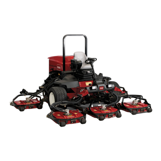
Groundsmaster
4700-D Rotary Mower
Model No. 30893—Serial No. 406680000 and Up
Model No. 30893TE—Serial No. 406680000 and Up
Model No. 30899—Serial No. 406680000 and Up
Model No. 30899TE—Serial No. 406680000 and Up
Form No. 3439-572 Rev A
®
4500-D or
*3439-572* A
Advertisement
Table of Contents

Related Manuals for Toro Groundsmaster 4500-D


Summary of Contents for Toro Groundsmaster 4500-D
- Page 1 4500-D or 4700-D Rotary Mower Model No. 30893—Serial No. 406680000 and Up Model No. 30893TE—Serial No. 406680000 and Up Model No. 30899—Serial No. 406680000 and Up Model No. 30899TE—Serial No. 406680000 and Up *3439-572* A Register at www.Toro.com. Original Instructions (EN)
- Page 2 Whenever you need service, genuine Toro parts, or additional information, contact an Authorized Service Dealer or Toro Customer Service and have the model and serial numbers of your product ready. Figure 1 identifies the location of the model and serial numbers on the right front frame of the product.
-
Page 3: Table Of Contents
Understanding the Turnaround Mode ....37 Checking the Cooling System ......61 Understanding Counterbalance......37 Cleaning the Cooling System......62 Understanding Toro Smart Power™ ....37 Brake Maintenance ..........63 Starting the Engine ........... 37 Adjusting the Service Brakes ......63 Shutting Off the Engine........ -
Page 4: Safety
Safety Hydraulic System Maintenance ......64 Hydraulic System Safety........64 Servicing the Hydraulic Fluid ......65 This machine has been designed in accordance with Checking the Hydraulic Lines and ANSI B71.4-2017 and with EN ISO 5395 when you Hoses............68 complete the setup procedures. -
Page 5: Safety And Instructional Decals
Safety and Instructional Decals Safety decals and instructions are easily visible to the operator and are located near any area of potential danger. Replace any decal that is damaged or missing. decal93-6681 93-6681 1. Cutting/dismemberment hazard, fan—stay away from moving parts. decal106-6755 106-6755 1. - Page 6 decal112-5297 112-5297 1. Warning—read the Operator's Manual; do not operate the machine unless you are trained. decal117-4764 2. Warning—read the Operator's Manual before towing the 117-4764 machine. 3. Tipping hazard— turn at low speeds; do not turn at high 1. Thrown object hazard—keep bystanders away. speeds;...
- Page 7 decalbatterysymbols Battery Symbols Some or all of these symbols are on your battery. 1. Explosion hazard 6. Keep bystanders away from the battery. 2. No fire, open flame, or 7. Wear eye protection; smoking explosive gases can cause blindness and other injuries.
- Page 8 decal121-3887 121-3887 1. Read the Operator’s Manual. decal136-3185 136-3185 1. Headlights—Off 5. Low 2. Headlights—On 6. Lower the left cutting unit. 3. High/Low—Auto 7. Lower the center cutting unit. 4. Traction controls 8. Lower the right cutting unit. decal127-3700 127-3700 For Groundsmaster 4700 Only 1.
- Page 9 decal136-3338 136-3338 1. TEC—7.5 A 6. Power seat—10 A 2. Power—10 A 7. Engine—10 A decal136-3566 136-3566 3. InfoCenter—2 A 8. TEC—2 A 4. Auxiliary power—10 A 9. Telematics—10 A 1. Read the Operator’s Manual for more information on servicing the machine. 5.
- Page 10 Affix over Part No. 112-5297 for CE* for 4500 series machines decal127-6447 127-6447 Note: This machine complies with the industry standard stability test in the static lateral and longitudinal tests with the maximum recommended slope indicated on the decal. Review the instructions for operating the machine on slopes in the Operator’s Manual as well as the conditions in which you would operate the machine to determine whether you can operate the machine in the conditions on that day and at that site.
- Page 11 Affix over Part No. 112-5297 for CE* for 4700 series machines decal127-6448 127-6448 Note: This machine complies with the industry standard stability test in the static lateral and longitudinal tests with the maximum recommended slope indicated on the decal. Review the instructions for operating the machine on slopes in the Operator’s Manual as well as the conditions in which you would operate the machine to determine whether you can operate the machine in the conditions on that day and at that site.
-
Page 12: Setup
Setup Loose Parts Use the chart below to verify that all parts have been shipped. Procedure Description Qty. Warning decal CE decal Replace the decals (CE machines only). Production-year decal Hood-latch bracket Rivet Install the hood latch (CE machines Washer only). -
Page 13: Installing The Hood Latch
Installing the Hood Latch CE Machines Only Parts needed for this procedure: Hood-latch bracket g012629 Figure 5 Rivet Washer 1. CE lock bracket 2. Bolt and nut Screw (1/4 x 2 inches) Align the washers with the holes on the inside of Locknut (1/4 inch) the hood. -
Page 14: Adjusting The Roller Scraper
1. Bolt 3. Arm of hood-latch bracket 2. Nut Procedure Contact your authorized Toro distributor for the correct mulching baffle. Thoroughly clean debris from the mounting holes on the rear wall and left wall of the chamber. Adjusting the Roller... -
Page 15: Preparing The Machine
Preparing the Machine No Parts Required Procedure Park the machine on a level surface. For Groundsmaster 4500 and 4700 machines, release the No. 4 and No. 5 cutting-unit cables (Figure 32). For Groundsmaster 4700 machines, release the No. 6 and No. 7 cutting-unit latches (Figure 35). -
Page 16: Product Overview
Tilt-Steering Pedal Product Overview To tilt the steering wheel toward you, press the foot pedal down, pull the steering tower toward you to Controls the most comfortable position, and release the pedal (Figure 10). To move the steering wheel away from you, press the foot pedal and release it when the steering wheel reaches the desired operating position. - Page 17 Note: If you have the switch in the H/L AUTO position, you cannot lower the decks from the fully-raised position unless the traction pedal is in neutral and the machine is stopped. Cruise-Control Switch The cruise-control switch locks in the cruise control to maintain the desired ground speed (Figure 12).
- Page 18 Armrest Adjustment Knob Rotate the knob to adjust the armrest angle (Figure 14). Seat-Back Adjustment Lever Move the lever to adjust the seat-back angle (Figure 14). Weight Gauge The weight gauge indicates when the seat is adjusted to the operator’s weight (Figure 14).
-
Page 19: Specifications
Specifications g322289 Figure 15 1. Cutting unit 1 3. Cutting unit 3 5. Cutting unit 5 7. Cutting unit 7 (4700 only) 2. Cutting unit 2 4. Cutting unit 4 6. Cutting unit 6 (4700 only) -
Page 20: Machine Specifications
Weight 88 kg (195 lb) Attachments/Accessories A selection of Toro approved attachments and accessories is available for use with the machine to enhance and expand its capabilities. Contact your Authorized Service Dealer or authorized Toro distributor or go to www.Toro.com for a list of all approved attachments and accessories. -
Page 21: Before Operation
Checking the Engine-Oil Operation Level Note: Determine the left and right sides of the machine from the normal operating position. Before you start the engine and use the machine, check the oil level in the engine crankcase; refer to Checking the Engine-Oil Level (page 50). - Page 22 Fuel filter plugging may occur for a time after you convert to biodiesel blends. Petroleum Diesel • For more information on biodiesel, contact your authorized Toro distributor. Cetane rating: 45 or higher Sulfur content: Low sulfur (<500 ppm) Adding Fuel Fuel Table...
-
Page 23: Checking The Tire Pressure
Checking the Tire Pressure Service Interval: Before each use or daily The correct air pressure in the tires is 138 kPa (20 psi). Important: Maintain the recommended pressure in all tires to ensure a good quality of cut and proper machine performance. Do not under-inflate g033359 the tires. -
Page 24: Checking The Interlock Switches
If it takes longer than 7 seconds, Service Interval: Before each use or daily adjust the braking valve. Call your authorized Toro distributor for assistance in making this adjustment. -
Page 25: Selecting A Blade
Selecting a Blade Standard Combination Sail This blade was designed to provide excellent lift and dispersion in almost any condition. If more or less lift and discharge velocity is required, consider a different blade. Attributes: Excellent lift and dispersion in most conditions Angled Sail (Not CE Compliant) The blade generally performs best in lower heights of... -
Page 26: Choosing Accessories
Choosing Accessories Optional Equipment Configurations Angle Sail Blade High-Lift, Parallel-Sail Mulching Baffle Roller Scraper Blade (Do not use with the mulching baffle) Grass Cutting: 1.9 to 4.4 Recommended in most May work well in light or Has been shown to Use it whenever the cm (3/4 to 1-3/4 inches) applications... -
Page 27: Using The Infocenter Lcd Display
Using the InfoCenter LCD InfoCenter Icon Description Display SERVICE DUE Indicates when scheduled service should be performed The InfoCenter LCD display shows information about Hours remaining until service your machine, such as the operating status, various diagnostics and other information about the machine Reset the service hours (Figure 22). -
Page 28: Using The Menus
InfoCenter Icon Description (cont'd.) InfoCenter Icon Description (cont'd.) Engine Engine start is denied Key switch Engine shutdown Cutting units are lowering Engine coolant is too hot Cutting units are raising Hydraulic fluid is too hot PIN code Sit down or engage parking brake Hydraulic fluid temperature Accessible only by entering PIN CAN bus... -
Page 29: Protected Menus
LCD Contrast Controls the contrast of the If you changed the PIN code and forgot the code, LCD display contact your authorized Toro distributor for assistance. Protected Menus Allows a person authorized From the M , use the center button to... - Page 30 Viewing and Changing the Protected Menu Settings In the Protected Menu, scroll down to Protect Settings. To view and change the settings without entering a PIN code, use the right button to change the Protect Settings to O To view and change the settings with a PIN code, use the left button to select O , set the PIN code, and turn the key to the O...
-
Page 31: During Operation
Turning the Smart Power ON/OFF During Operation In the settings menu, scroll down to Smart Power. During Operation Safety Press the right button to switch between O General Safety Press the left button to exit. • The owner/operator can prevent and is responsible for accidents that may cause personal injury or Setting the Counterbalance property damage. - Page 32 Roll Bar • Identify hazards at the base of the slope. • A cab installed by Toro is a roll bar. If there are hazards, mow the slope with a • pedestrian-controlled machine. Always wear your seat belt.
-
Page 33: Understanding The Operating Characteristics Of The Machine
Understanding the operate in low speed range. This setting is preferable for operation in a shop area, loading or Operating Characteristics unloading from a trailer, climbing steep inclines, or any other operation where the higher traction of the Machine speeds of the high speed range is not desired. •... -
Page 34: Using The High And Low Speed Range Switch
Using the High and Low Speed Range Switch This machine is equipped with 2 traction speed ranges; low and high. The speed range switch allows you to select the following positions (Figure 25): • High/Low Auto range: Selecting the H/L AUTO position allows the machine to automatically select between the low and high speed ranges. -
Page 35: Setting The Maximum Traction Speed (Pedal Stop)
is limited from 0 to 75% and matched to the full stroke of the traction pedal. This setting increases the traction pedal resolution, resulting in improved control. How far you move the traction pedal changes how much the machine's speed changes. Using the Brake Pedals Important: In emergency braking situations,... -
Page 36: Operating The Cruise Control
Operating the Cruise Adjusting the Cruise Control Speed Control After the cruise control switch is enabled on the console Figure 29, use the InfoCenter to adjust the Setting the Cruise Control speed setting of the cruise control (Figure 30). The cruise-control switch locks in the cruise control to maintain the desired ground speed. -
Page 37: Understanding The Acceleration Mode
High—the least amount of weight on cutting units Understanding the and the highest weight on machine drive wheels Turnaround Mode Understanding Toro Smart The turnaround mode allows you convenient, 1-touch control to raise the cutting units above the turf while Power™... -
Page 38: Shutting Off The Engine
When the temperature is less than -7°C (20°F), Pull the PTO switch to engage the cutting units. the starter motor can be run for 30 seconds on Note: The engine speed automatically rises to then 60 seconds off for 2 attempts. high idle when you lower the cutting units and Important: Shut off the engine and allow the... -
Page 39: Operating Tips
Resolving After-Cut Appearance after cut appearance. Refer to the After-cut Appearance Troubleshooting Guide available at www.Toro.com. Maintaining the Machine after Mowing Using Proper Mowing Techniques After mowing, thoroughly wash the machine with a •... -
Page 40: After Operation
Securing the Cutting Units After Operation Ensure that the PTO is disengaged. General Safety Park the machine on a level surface. • Engage the parking brake. Shut off the engine, remove the key, and wait for all movement to stop before you leave the Fully raise the cutting units. -
Page 41: Using The Transport Latches
With the cutting units lowered, slip the loop of the lanyard into the slot in the reinforcement plate of the roller support (Figure 34). g225485 Figure 34 1. Reinforcement-plate slot 2. Lanyard loop g038610 Figure 35 (roller support) Hauling the Machine Using the Transport •... -
Page 42: Locating The Tie-Down Points
Locating the Tie-Down Rotate each valve 3 turns counter-clockwise to open and allow the fluid to bypass internally. Points Note: Do not open the valve more than 3 turns. Because fluid is bypassed, you can Note: Use properly-rated DOT-approved straps in 4 move the machine slowly without damaging the corners to tie down the machine. -
Page 43: Maintenance
Remove the key from the To ensure safe, optimal performance of the switch before you perform any maintenance. machine, use only genuine Toro replacement parts. Replacement parts made by other • Allow machine components to cool before manufacturers could be dangerous, and such use performing maintenance. -
Page 44: Daily Maintenance Checklist
Maintenance Service Maintenance Procedure Interval • Torque the wheel lug nuts. Every 200 hours • Change the engine oil and filter. Every 250 hours • Service the air cleaner (earlier if the air-cleaner indicator shows red, and more frequently in extremely dirty or dusty conditions). •... - Page 45 For the week of: Maintenance Check Item Monday Tuesday Wednesday Thursday Friday Saturday Sunday Check for unusual operating noises. Check the hydraulic-fluid level. Check the hydraulic hoses for damage. Check for fluid leaks. Check the fuel level. Check the tire pressure. Check the instrument operation.
-
Page 46: Pre-Maintenance Procedures
Pre-Maintenance Procedures Lifting the Machine Use the following as points to lift the machine: Front of the machine—at the frame of the machine, forward of the wheel-drive motors (Figure Important: Do not support the machine at the wheel-drive motors. Keep the lifting equipment clear of hydraulic tubing and hoses. -
Page 47: Accessing The Hydraulic Lift Compartment
Accessing the Hydraulic Lubrication Lift Compartment Greasing the Bearings and Tilt the seat to access the hydraulic lift compartment as shown in Figure Bushings Service Interval: Every 50 hours (also after every washing). Grease specification: No. 2 lithium grease The grease fitting locations and quantities are as follows: •... - Page 48 • • Steering-cylinder ball joints (2) as shown in Figure Cutting-unit spindle-shaft bearings (2 per cutting unit) as shown in Figure 47 Note: You can use either fitting, whichever is more accessible. Pump grease into the fitting until a small amount appears at the bottom of the spindle housing (under the cutting unit).
-
Page 49: Engine Maintenance
Engine Maintenance Engine Safety • Shut off the engine and remove the key before checking the oil or adding oil to the crankcase. g198631 • Do not change the governor speed or overspeed the engine. Servicing the Air Cleaner Service Interval: Every 400 hours Check the air-cleaner body for damage which could cause an air leak. -
Page 50: Servicing The Engine Oil
Preferred oil: SAE 15W-40 (above 0°F) • Alternate oil: SAE 10W-30 or 5W-30 (all temperatures) Toro Premium Engine Oil is available from your authorized Toro distributor in either 15W-40 or 10W-30 viscosity grades. See the Parts Catalog for part numbers. -
Page 51: Fuel System Maintenance
Crankcase Oil Capacity Fuel System Approximately 5.7 L (6 US qt) with the filter. Maintenance Changing the Engine Oil and Filter DANGER Service Interval: Every 250 hours Under certain conditions, diesel fuel and fuel vapors are highly flammable and explosive. A Note: To reset the service due indicator in the fire or explosion from fuel can burn you and... -
Page 52: Servicing The Fuel-Water Separator
Servicing the Fuel-Water Replacing the Fuel-Filter Canister Separator Service Interval: Every 400 hours—Replace the fuel-filter canister. Replace the fuel-filter canister as shown in Figure g198661 Figure 54 Draining Water from the Fuel/Water Separator Service Interval: Before each use or daily—Drain water or other contaminants from the fuel filter/water separator Drain water from the fuel/water separator as shown... -
Page 53: Servicing The Fuel Filter
Servicing the Fuel Filter Cleaning the Fuel-Pickup Tube Screen Service Interval: Every 400 hours Clean the area around the fuel-filter head The fuel-pickup tube, located inside the fuel tank, is (Figure 57). equipped with a screen to help prevent debris from entering the fuel system. -
Page 54: Priming The Fuel System
Rinse with clear water. Coat the battery posts and cable connectors with Grafo 112X (skin-over) grease (Toro Part No. 505-47) or petroleum jelly to prevent corrosion. Charging and Connecting... - Page 55 Remove the rubber boot from the positive terminal and inspect the battery. Remove the negative cable (black) from the negative (-) terminal and the positive cable (red) from the positive (+) terminal of the battery (Figure 59). WARNING Incorrect battery cable routing could damage the machine and cables, causing sparks.
-
Page 56: Locating The Fuses
Locating the Fuses The fuse block for the machine is located in the right storage box g010255 Figure 62 1. Fuses decal136-3338 Close the cover of the right storage box and Figure 60 secure the cover with the latch (Figure 61). -
Page 57: Drive System Maintenance
Figure 64 1. Front drive wheels Repeat step for the other drive wheel. If either wheel moves, contact your authorized g225611 Toro distributor to have the planetary drive Figure 63 rebuilt. Checking the Planetary Checking for End-Play in Gear-Drive Lubricant... -
Page 58: Changing The Planetary-Gear-Drive Oil
The oil level should be at the bottom of the check-plug hole. g225609 Figure 67 g225606 Figure 66 1. Drain-plug hole 3. Check plug 2. Fill plug 4. Drain plug 1. Check-plug hole 2. Check plug Place a drain pan under the planetary hub, If the oil level is low, remove the fill plug at the remove the drain plug at the 6 o’clock position, 12 o’clock position and add oil until it begins to... -
Page 59: Checking The Rear Axle And Gearbox For Leaks
Filling the Planetary-Gear-Drive Checking the Rear Axle and with Lubricant Gearbox for Leaks Through the fill-plug hole, slowly fill the planetary Service Interval: Before each use or daily with 0.65 L (22 fl oz) of high quality SAE 85W-140 wt gear lube. Visually inspect the rear axle and rear-axle gearbox for leaks. -
Page 60: Changing The Rear-Axle Lubricant
lube or until the lubricant is up to the bottom of the hole. Install the check plug. Checking the Rear-Axle-Gearbox Lubricant Service Interval: Every 400 hours g009716 The gear box is filled with SAE 85W-140 gear lube. Figure 72 The capacity is 0.5 L (16 fl oz). Visually inspect for 1. -
Page 61: Cooling System Maintenance
Cooling System Note: The front measurement must be 3 mm (1/8 inch) less than the rear measurement. Maintenance Cooling System Safety • Swallowing engine coolant can cause poisoning; keep out of reach from children and pets. • Discharge of hot, pressurized coolant or touching a hot radiator and surrounding parts can cause severe burns. -
Page 62: Cleaning The Cooling System
Cleaning the Cooling System Service Interval: Before each use or daily—Remove debris from the engine area, oil cooler, and radiator (clean them more frequently in dirty conditions). This machine is equipped with a hydraulically driven fan drive system that automatically (or manually) reverses to reduce oil cooler/radiator and screen debris buildup. -
Page 63: Brake Maintenance
Brake Maintenance Adjusting the Service Brakes Adjust the service brakes when there is more than 25 mm (1 inch) of free travel of the brake pedal, or when the brakes do not work effectively. Free travel is the distance the brake pedal moves before you feel braking resistance. -
Page 64: Belt Maintenance
Belt Maintenance Hydraulic System Maintenance Servicing the Alternator Belt Hydraulic System Safety Service Interval: Every 100 hours • Seek immediate medical attention if fluid is injected into skin. Injected fluid must be surgically removed Proper tension of the belt allows 10 mm (3/8 inch) of within a few hours by a doctor. -
Page 65: Servicing The Hydraulic Fluid
Important: Toro Premium Synthetic Biodegradable Hydraulic Fluid is the only synthetic biodegradable fluid approved by Toro. This fluid is compatible with the elastomers used in Toro hydraulic systems and is suitable for a wide-range of temperature conditions. This fluid is... - Page 66 (sooner if the service interval indicator is in the red zone). Changing the Hydraulic Fluid Use Toro replacement filters Part No. 94-2621 for the rear (cutting units) of the machine and Part No. Service Interval: Every 2,000 hours—If you 75-1310 for the front (charge) of the machine.
- Page 67 Lower and secure the operator’s seat. Replace the return filter at the right side of the machine (Figure 84). Start the engine and let it run for about 2 minutes to purge air from the system. Shut off the engine and check for leaks.
-
Page 68: Checking The Hydraulic Lines And Hoses
Checking the Hydraulic Cutting Unit Maintenance Lines and Hoses Removing the Cutting Units Service Interval: Before each use or daily Park the machine on a level surface, engage the Every 2 years parking brake, lower the cutting units, shut off Inspect the hydraulic lines and hoses daily for the engine, and remove the key. -
Page 69: Installing The Cutting Units
Installing the Cutting Units Assembling the Front Roller Press the first bearing into the roller housing Move the cutting unit into position in front of the (Figure 87). Press on the outer race only or machine. equally on the inner and outer race. Slide the cutting unit-carrier frame onto the Insert the spacer (Figure... -
Page 70: Blade Maintenance
Blade Maintenance Compare the 12 o’clock measured height to the height-of-cut setting. It should be within 0.7 mm (0.030 inch). The 3 and 9 o’clock heights should Blade Safety be 1.6 to 6.0 mm (0.060 to 0.240 inch) higher than the 12 o’clock setting and within 2.2 mm •... -
Page 71: Removing And Installing The Cutting-Unit Blade(S)
Replace the blade if it hits a solid object, is out shredded. Sharpen the cutting edges to correct this of balance, or is bent. Always use genuine Toro condition. replacement blades to ensure safety and optimum performance. - Page 72 Note: Remove the blades and sharpen them on a grinder. After sharpening the cutting edges, install the blade with the anti-scalp cup and blade bolt; refer to Removing and Installing the Cutting-Unit Blade(s) (page 71). Ensure that the blade is straight and parallel; lay the blade on a level surface and check its ends.
-
Page 73: Storage
Storage Remove and discard the oil filter. Install a new oil filter. Refill the oil pan with designated quantity of Storage Safety motor oil. • Shut off the engine, remove the key, and wait Turn the key in the switch to the O position, for all movement to stop before you leave the start the engine, and run it at idle speed for... - Page 74 Notes:...
- Page 75 The Toro Company (“Toro”) respects your privacy. When you purchase our products, we may collect certain personal information about you, either directly from you or through your local Toro company or dealer. Toro uses this information to fulfil contractual obligations - such as to register your warranty, process your warranty claim or to contact you in the event of a product recall - and for legitimate business purposes - such as to gauge customer satisfaction, improve our products or provide you with product information which may be of interest.
- Page 76 Countries Other than the United States or Canada Customers who have purchased Toro products exported from the United States or Canada should contact their Toro Distributor (Dealer) to obtain guarantee policies for your country, province, or state. If for any reason you are dissatisfied with your Distributor's service or have difficulty obtaining guarantee information, contact your Authorized Toro Service Center.