Table of Contents
Advertisement
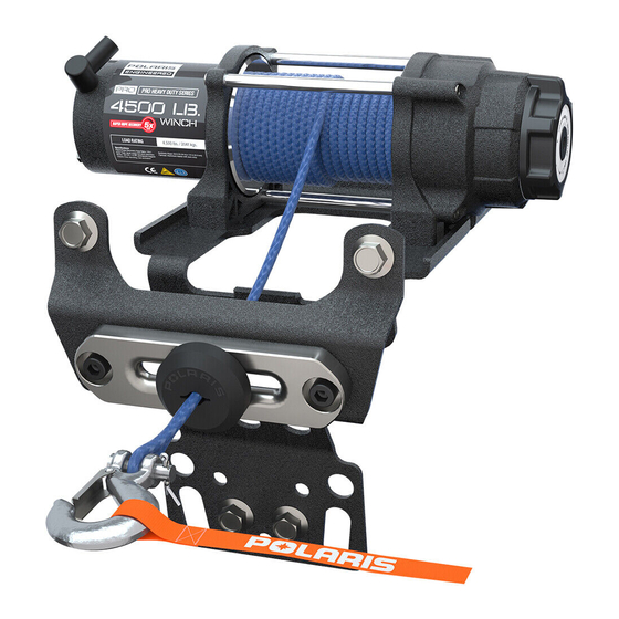
POLARIS
4500 PRO HD WINCH KIT
® ®
P/N 2883861
APPLICATION
Verify accessory fitment at Polaris.com.
BEFORE YOU BEGIN
Read these instructions and check to be sure all parts and tools are accounted for. Please retain these
installation instructions for future reference and parts ordering information.
KIT CONTENTS
This Kit includes:
REF
QTY
PART DESCRIPTION
1
1
Harness Adapter
2
2
Dash Switch
3
2
Routing Clip
4
1
Wireless Remote Holder
5
1
Wireless Remote Receiver
6
1
Wireless Remote
7
4
Locking Nut - M12 X 1.75
8
1
Fairlead Mounting Bracket
Instr 9929140
Rev 01 2018-08
Page 1 of 17
PART NUMBER
2413447
4015688
-
-
-
-
7547441
5258106
Advertisement
Table of Contents

Related Manuals for Polaris 4500 PRO HD


Summary of Contents for Polaris 4500 PRO HD
- Page 1 POLARIS 4500 PRO HD WINCH KIT ® ® P/N 2883861 APPLICATION Verify accessory fitment at Polaris.com. BEFORE YOU BEGIN Read these instructions and check to be sure all parts and tools are accounted for. Please retain these installation instructions for future reference and parts ordering information.
-
Page 2: Part Description
Your Polaris ® 4500 Pro HD Winch Kit is exclusively designed for your vehicle. Please read the installation instructions thoroughly before beginning. Installation is easier if the vehicle is clean and free of debris. For your safety, and to ensure a satisfactory installation, perform all installation steps correctly in the sequence shown. -
Page 3: Installation Instructions
INSTALLATION INSTRUCTIONS c. Disconnect black negative (-) cable from CAUTION battery FIRST. BEFORE STARTING INSTALLATION, always ensure vehicle is properly secured on a flat stable surface to avoid accidental tipping, unwanted movement and to prevent personal injury and/or damage to equipment. Shift vehicle transmission into “PARK”. - Page 4 4. INSTALL WINCH ASSEMBLY. 5. INSTALL AUTOSTOP FAIRLEAD ASSEMBLY. a. Slide winch mounting bracket into position a. Install Autostop fairlead to fairlead mounting from the passenger side as shown. Orient and bracket using the provided screws align winch mounting bracket to front locking nuts suspension bracket and steering bracket as TORQUE...
- Page 5 , making sure that the tapered edge with the embossed "Polaris" logo is facing forward as shown. Install hook to the rope by inserting clevis pin through hook and rope and securing with a cotter pin.
- Page 6 9. CONNECT ALL ELECTRICAL COMPONENTS. c. Connect the Autostop fairlead connector (13A) to the control box connector (19A). NOTE Refer to the Electrical Connection Reference Guide section at the back of the instruction manual for images and detailed harness connection illustrations of the proper electrical connections to aid in the remaining electrical connections.
- Page 7 f. Next connect the pulse bar dash switch g. For vehicles with a busbar you will need to first connector (23A) to the pulse bar connection remove the cable connection nut from the as shown. For MY19 and newer vehicles skip keyed power terminal and install the orange step 9g and proceed to step 9h.
- Page 8 i. Connect the red positive (+) and black negative 10. CONNECT BATTERY. (–) power cables to the corresponding positive WARNING (+) and negative (–) terminals on the pulse bar or busbar. When BOTH battery cables are disconnected ALWAYS reconnect AND tighten red positive (+) MY 19 and newer vehicle use the provided cable to battery FIRST.
- Page 9 11. REINSTALL SEAT. 14. OPTIONAL STEP - INSTALL WIRELESS REMOTE. a. Lift the driver side seat latch located behind seat bottom and firmly press down on seat a. Wireless remote holder can be installed in bottom to reinstall the driver seat .
- Page 10 16. VERIFY WINCH FUNCTION. a. With the vehicle key in the “ON” position, check winch for proper operation. i. Shift winch into each of the three gear settings, HIGH/LOW/NEUTRAL, and verify proper function. ii. Test function of Autostop feature. When reeling in the winch rope, confirm that the winch will turn off automatically when the rubber puck reaches the aluminum fairlead.
-
Page 11: Winch Operation
WINCH OPERATION WIRELESS REMOTE OPERATION AUTOSTOP OPERATION NOTE • The Autostop system is meant to help prevent damage to the winch system from over-tightening of The remote will automatically turn itself off after 30 the rope/cable, but is not meant to prevent all seconds of inactivity. -
Page 12: Gear Selection
GEAR SELECTION The dual speed winch is equipped with three different • To shift into low, rotate the gear shifting knob gear settings. “HIGH”, “NEUTRAL” and “LOW”. counter-clockwise until the “L” marking shows thru the cutout window on the shift knob. See photo WARNING below. -
Page 13: Trobleshooting
TROBLESHOOTING SYMPTOM POSSIBLE CAUSES RECOMMENDED SOLUTION Dead vehicle Incorrect, damaged, or Verify all winch electrical connections are per instruction battery corroded electrical manual and free of damage and/or corrosion. connections Winch will not Contactor not receiving Turn vehicle key on. operate power Wireless remote not... -
Page 14: Service Kits
PRO Service Handle Kit: PN 5454752 Winch Hardware Kit: PN 2206301 PART DESCRIPTION PART DESCRIPTION 4500 Pro HD (Rapid Rope Screw, SH - M10 X 1.5 X 25 Recovery) Service Handle Kit Screw, HXFL - M12 X 1.75 X 25 Screw, HXFL M8 X 1.25 X 20... - Page 15 Universal Wireless Remote Kit: PN 2881287 PART DESCRIPTION Wireless Receiver Wireless Remote Wireless Remote Holder Routing Clip Screw - #10 x 3/4 Screw - M6 X 1.0 X 25 Instr 9929140 Rev 01 2018-08 Page 15 of 17...
- Page 16 ELECTRICAL REFERENCE GUIDE Wireless Receiver Detail Harness Adapter Detail (MY18 and older) Winch Harness Detail Control Box Detail Autostop Detail Instr 9929140 Rev 01 2018-08 Page 16 of 17...
-
Page 17: Feedback Form
FEEDBACK FORM A feedback form has been created for the installer to provide any comments, questions FEEDBACK FORM or concerns about the installation instructions. The form is viewable on mobile devices by scanning the QR code or by clicking HERE if viewing on a PC.