
Related Manuals for Asus AAEON BOXER-8521AI


Summary of Contents for Asus AAEON BOXER-8521AI
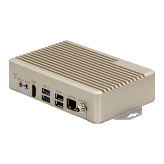
- Page 1 BOXER-8521AI Compact Fanless Embedded AI@Edge Box PC with Google® Edge TPU™ User’s Manual 1 Distributed by www.texim-europe.com...
- Page 2 Copyright Notice This document is copyrighted, 2020. All rights are reserved. The original manufacturer reserves the right to make improvements to the products described in this manual at any time without notice. No part of this manual may be reproduced, copied, translated, or transmitted in any form or by any means without the prior written permission of the original manufacturer.
- Page 3 Acknowledgements All other products’ name or trademarks are properties of their respective owners. Google® and Google Edge TPU™ are trademarks of Google LLC ⚫ ITE is a trademark of Integrated Technology Express, Inc. ⚫ IBM and VGA are trademarks of International Business Machines Corporation. ⚫...
- Page 4 Packing List Before setting up your product, please make sure the following items have been shipped: Item Quantity BOXER-8521AI ⚫ If any of these items are missing or damaged, please contact your distributor or sales representative immediately. Distributed by www.texim-europe.com...
- Page 5 About this Document This User’s Manual contains all the essential information, such as detailed descriptions and explanations on the product’s hardware and software features (if any), its specifications, dimensions, jumper/connector settings/definitions, and driver installation instructions (if any), to facilitate users in setting up their product. Users may refer to the product page at AAEON.com for the latest version of this document.
- Page 6 Safety Precautions Please read the following safety instructions carefully. It is advised that you keep this manual for future references All cautions and warnings on the device should be noted. All cables and adapters supplied by AAEON are certified and in accordance with the material safety laws and regulations of the country of sale.
- Page 7 As most electronic components are sensitive to static electrical charge, be sure to ground yourself to prevent static charge when installing the internal components. Use a grounding wrist strap and contain all electronic components in any static-shielded containers. If any of the following situations arises, please the contact our service personnel: Damaged power cord or plug Liquid intrusion to the device iii.
- Page 8 FCC Statement This device complies with Part 15 FCC Rules. Operation is subject to the following two conditions: (1) this device may not cause harmful interference, and (2) this device must accept any interference received including interference that may cause undesired operation.
- Page 9 China RoHS Requirements (CN) 产品中有毒有害物质或元素名称及含量 AAEON System QO4-381 Rev.A0 有毒有害物质或元素 部件名称 铅 汞 镉 六价铬 多溴联苯 多溴二苯 醚(PBDE) (Pb) (Hg) (Cd) (Cr(VI)) (PBB) 印刷电路板 × ○ ○ ○ ○ ○ 及其电子组件 外部信号 × ○ ○ ○ ○ ○ 连接器及线材 外壳 ○...
- Page 10 China RoHS Requirement (EN) Hazardous and Toxic Materials List AAEON System QO4-381 Rev.A0 Hazardous or Toxic Materials or Elements Component Name PCB and Components Wires & Connectors for Ext.Connections Chassis CPU & RAM HDD Drive LCD Module Optical Drive Touch Control Module Battery This form is prepared in compliance with the provisions of SJ/T 11364.
-
Page 11: Table Of Contents
Table of Contents Chapter 1 - Product Specifications..................1 Specifications ......................2 Product Notice ......................4 Chapter 2 – Hardware Information ..................5 Dimensions ....................... 6 Jumpers and connectors..................8 List of Jumpers ......................10 2.3.1 Setting Jumpers ..................10 2.3.2 COM Port Mode Select Header (JP1) .......... - Page 12 2.4.17 MIPI CSI Connector (P1) ................ 31 2.4.18 System Reset Button (SW1) ..............32 2.4.19 Boot Mode Select Switch (SW2) ............33 Hardware Assembly ....................34 Chapter 3 – OS Flash Guide ....................35 Before Installation ....................36 Connecting to PC/Entering Fastboot Mode ............ 37 Flash Image to Board ....................
-
Page 13: Chapter 1 - Product Specifications
Chapter 1 Chapter 1 - Product Specifications Distributed by www.texim-europe.com... -
Page 14: Specifications
Specifications System AI Accelerator Google Edge TPU ML accelerator coprocessor NXP i.MX 8M SoC (Quad-core Cortex-A53, plus Cortex-M4F) System Memory 1GB LPDDR4x Storage Device 8GB eMMC Display Interface HDMI 2.0 x 1 Ethernet 10/100/1000Base-TX x 1 HDMI 2.0a x 1 USB Type A x 2 for USB3.2 Gen 1 USB Type A x 2 for USB2.0 RJ-45 x 1 for GbE LAN &... - Page 15 Power Supply Power Requirement POE/PD (802.3at) 12Vdc (DC Jack w/lockable) Mechanical Mounting Wall mount Dimensions (W x D x H) 6.92” x 3.94” x 1.54” (175.8 mm x 100.0 mm x 39.0 mm) Gross Weight 2.31 lbs. (1.05 kg) Net Weight 1.28 lbs.
-
Page 16: Product Notice
Product Notice Micro-USB: Micro-USB port is ideally for flashing image only. USB ports: USB ports do not support USB DVD ROM because of file system. USB 3.2 Gen 1: USB 3.2 Gen 1 is the current name for 5Gbps specification, formerly USB 3.0. -
Page 17: Chapter 2 - Hardware Information
Chapter 2 Chapter 2 – Hardware Information Distributed by www.texim-europe.com... -
Page 18: Dimensions
Dimensions Distributed by www.texim-europe.com... - Page 19 40-pin I/O View Distributed by www.texim-europe.com...
-
Page 20: Jumpers And Connectors
Jumpers and connectors Board Top Distributed by www.texim-europe.com... - Page 21 Board Bottom Distributed by www.texim-europe.com...
-
Page 22: List Of Jumpers
List of Jumpers The board has a number of jumpers that allow you to configure your system to suit your application. The table below shows the function of each of the board's jumpers Label Function COM Port Mode Select Header 2.3.1 Setting Jumpers You can configure your system to match the needs of your application by setting... -
Page 23: Com Port Mode Select Header (Jp1)
2.3.2 COM Port Mode Select Header (JP1) COM Port Mode can be set by configuring Pins 1-2 and Pins 3-4 to be open or closed. Mode Select MODE_1 MODE_2 Closed Closed Open RS232 Closed Open Closed RS485: RX Closed Open Open RS485: TX Slew Rate Control is set by Pins 5-6... - Page 24 JP1 Pin Definitions Pin Name Signal Type Signal Level UART3_MODE_1 UART3_MODE_2 UART3_SLEW Note: Only connect pins in pairs of 1-2, 3-4, 5-6. To avoid unwanted operation or damage to the system, do not connect pins in any other configuration. Distributed by www.texim-europe.com...
-
Page 25: List Of Connectors
List of Connectors The board has a number of connectors that allow you to configure your system to suit your application. The table below shows the function of each of the board's connectors Label Function CN1/CN2/CN3 Google Edge TPU module Connectors 40-pin Expansion Header HDMI Port Dual USB3.2 Gen1 Port... -
Page 26: Google Edge Tpu Module Connector (Cn1)
2.4.1 Google Edge TPU Module Connector (CN1) Signal Signal ECSPI2_SS0 ECSPI2_SCLK ECSPI2_MISO ECSPI1_SCLK ECSPI1_MISO ECSPI1_MOSI ECSPI1_SS0 PWM4 SAI2_MCLK SAI2_TXD SAI2_TXFS SAI2_TXC SAI2_RXD SAI2_RXC SAI2_RXFS SAI1_TXD2 SAI1_RXD0 SAI1_TXD5 SAI1_TXD4 Distributed by www.texim-europe.com... - Page 27 Signal Signal ENET_nINT SAI1_TXC ENET_nRST SAI1_TXD0 GPIO7 SAI1_TXFS GPIO8 SAI5_RXD1 GPIO6 SAI5_MCLK GPIO12 SAI5_RXD3 JTAG_TCK SAI5_RXD2 JTAG_nTRST SAI5_RXC JTAG_TDO SAI5_RXD0 JTAG_TMS SAI5_RXFS JTAG_TDI BOOT_MODE1 SYS_NRST BOOT_MODE0 HDMI_CLK_P HDMI_CLK_N HDMI_TX0_N HDMI_TX2_N HDMI_TX0_P HDMI_TX2_P HDMI_TX1_P HDMI_AUX_N HDMI_TX1_N HDMI_AUX_P HDMI_DDC_SDA PWRON_B HDMI_DDC_SCL PWM1 HDMI_HPD PWM2 Distributed by www.texim-europe.com...
-
Page 28: Google Edge Tpu Module Connector (Cn2)
Signal Signal HDMI_CEC PWM3 DCDC_5V DCDC_5V DCDC_5V DCDC_5V DCDC_5V DCDC_5V DCDC_5V DCDC_5V 2.4.2 Google Edge TPU Module Connector (CN2) Signal Signal MIPI_CSI1_D2_N MIPI_CSI1_D2_P MIPI_CSI1_D0_N MIPI_CSI1_D0_P MIPI_CSI1_CLK_N MIPI_CSI1_CLK_P MIPI_CSI1_D1_N MIPI_CSI1_D1_P Distributed by www.texim-europe.com... - Page 29 Signal Signal MIPI_CSI1_D3_N MIPI_CSI1_D3_P USB1_D_P USB1_D_N USB1_TX_P USB1_TX_N USB2_D_P USB1_RX_P USB2_D_N USB1_RX_N USB2_TX_P USB2_RX_P USB2_TX_N USB2_RX_N USB2_VBUS USB1_ID Distributed by www.texim-europe.com...
-
Page 30: Google Edge Tpu Module Connector (Cn3)
Signal Signal USB2_VBUS I2C3_SDA USB1_VBUS I2C3_SCL USB1_VBUS I2C2_SDA I2C2_SCL UART3_TXD UART1_TXD UART1_RXD UART3_RXD SPDIF_RX 2.4.3 Google Edge TPU Module Connector (CN3) Signal Signal ECSPI1_SS1 ENET_MDIO NAND_CLE Distributed by www.texim-europe.com... - Page 31 Signal Signal ENET_MDC ENET_TX_CTL ENET_TD3 ENET_TD2 NAND_DATA07 ENET_TD0 ENET_TD1 NAND_DATA03 ENET_TDC SD_nCD SD_CMD ENET_RXC SD_DAT0 ENET_RX_CTL ENET_RD2 SD_DAT1 ENET_RD0 SD_DAT2 ENET_RD1 SD_nRST ENET_RD3 SD_DAT3 SD_CLK HDMI_REFCLK_P HDMI_REFCLK_N Distributed by www.texim-europe.com...
- Page 32 Signal Signal POR_B NVCC_ENET_2V5 DCDC_3V3 NVCC_ENET_2V5 DCDC_3V3 NVCC_ENET_2V5 DCDC_3V3 DCDC_3V3 VDDA_1V8 VDDA_1V8 VDD_3V3 VDDA_1V8 VDD_3V3 VDDA_1V8 VDD_3V3 VDDA_1V8 VDD_3V3 Distributed by www.texim-europe.com...
-
Page 33: 40-Pin Expansion Header (Cn4)
2.4.4 40-Pin Expansion Header (CN4) Pin Name Signal Type Signal Level VDD_3V3 +3.3V DCDC_5V I2C2_SDA DCDC_5V I2C2_SCL UART3_TXD UART1_TXD UART1_RXD UART3_RXD SAI1_TXC GPIO6 PWM3 NAND_DATA03 VDD_3V3 +3.3V ECSPI2_SCLK ECSPI1_MOSI ECSPI1_MISO Distributed by www.texim-europe.com... - Page 34 Pin Name Signal Type Signal Level ECSPI2_MISO ECSPI1_SCLK ECSPI1_SS0 ECSPI1_SS1 I2C3_SDA I2C3_SCL GPIO7 GPIO8 PWM1 PWM2 SAI1_TXFS ECSPI2_SS0 NAND_DATA07 SAI1_RXD0 SAI1_TXD0 Distributed by www.texim-europe.com...
-
Page 35: Hdmi Port (Cn5)
2.4.5 HDMI Port (CN5) Pin Name Signal Type Signal Level HDMI_TXD2_CON_P DIFF HDMI_TXD2_CON_N DIFF HDMI_TXD1_CON_P DIFF HDMI_TXD1_CON_N DIFF HDMI_TXD0_CON_P DIFF HDMI_TXD0_CON_N DIFF HDMI_TXC_CON_P DIFF HDMI_TXC_CON_N DIFF HDMI_CEC_CON +3.3V HDMI_Utility/HEAC+_CN HDMI_DDC_SCL_5V0 HDMI_DDC_SDA_5V0 VDD_5V0_HDMI_CON HDMI_HPD_CON Distributed by www.texim-europe.com... -
Page 36: Dual Usb 3.2 Gen 1 Port (Cn6)
2.4.6 Dual USB 3.2 Gen 1 Port (CN6) Pin Name Signal Type Signal Level USB_VBUS_2 USB_HUB_DN2 DIFF USB_HUB_DP2 DIFF USB2_RX_N DIFF USB2_RX_P DIFF USB2_TX_N DIFF USB2_TX_P DIFF USB_VBUS_1 USB_HUB_DN1 DIFF USB_HUB_DP1 DIFF USB1_RX_N DIFF USB1_RX_P DIFF USB1_TX_N DIFF USB1_TX_P DIFF Distributed by www.texim-europe.com... -
Page 37: Micro Usb Port (Cn7)
2.4.7 Micro USB Port (CN7) Pin Name Signal Type Signal Level USB1_VBUS USB1_D_N DIFF USB1_D_P DIFF USB1_ID 2.4.8 Dual USB 2.0 Port (CN8) Pin Name Signal Type Signal Level USB_VBUS USB_HUB_DN3 DIFF USB_HUB_DP3 DIFF USB_VBUS Distributed by www.texim-europe.com... -
Page 38: Fan Control Connector (Cn9)
Pin Name Signal Type Signal Level USB_HUB_DN4 DIFF USB_HUB_DP4 DIFF 2.4.9 Fan Control Connector (CN9) Pin Name Signal Type Signal Level DCDC_5V NAND_CLE 2.4.10 COM Port Connector (CN11) Pin Name Signal Type Signal Level 485_D- RXC_3_485_D+ TXC_3 Distributed by www.texim-europe.com... -
Page 39: Micro Sd Card Slot (Cn12)
Pin Name Signal Type Signal Level Note: COM Port Mode and Slew Control can be set by JP1. 2.4.11 Micro SD Card Slot (CN12) Pin Name Signal Type Signal Level SD_DAT2 +1.8V SD_DAT3 +1.8V SD_CMD +1.8V VSD_3V3 +3.3V SD_CLK SD_DAT0 +1.8V SD_DAT1 +1.8V... -
Page 40: Dc-In Jack (Cn13)
2.4.12 DC-In Jack (CN13) Pin Name Signal Type Signal Level +V12_IN 2.4.13 LAN with PoE PD Port (CN14) Pin Name Signal Type Signal Level MDIP0_0_TF DIFF MDIN0_0_TF DIFF MDIP1_0_TF DIFF MDIP2_0_TF DIFF MDIN2_0_TF DIFF MDIN1_0_TF DIFF MDIP3_0_TF DIFF Distributed by www.texim-europe.com... -
Page 41: Line Out 3.5Mm Jack (Cn15)
Pin Name Signal Type Signal Level MDIN3_0_TF DIFF LED2_1000M/CFG_LDO1_0 LDO1_0 +3.3V LDO0_0 LED1_100M/CFG_LDO0_0 2.4.14 Line Out 3.5mm Jack (CN15) Pin Name Signal Type Signal Level GND_AUDIO LOUTR LOUTL Distributed by www.texim-europe.com... -
Page 42: Mic In 3.5Mm Jack (Cn16)
2.4.15 Mic In 3.5mm Jack (CN16) Pin Name Signal Type Signal Level GND_AUDIO IN2N IN2P 2.4.16 DMIC Connector (CN17/18) Pin Name Signal Type Signal Level DMIC_PWR +1.8V IN1P DMIC_SCL Distributed by www.texim-europe.com... -
Page 43: Mipi Csi Connector (P1)
2.4.17 MIPI CSI Connector (P1) Pin Name Signal Type Signal Level MIPI_CSI1_D0_N DIFF MIPI_CSI1_D0_P DIFF MIPI_CSI1_CLK_N DIFF MIPI_CSI1_CLK_P DIFF MIPI_CSI1_D1_N DIFF MIPI_CSI1_D1_P DIFF MIPI_CSI1_D2_N DIFF MIPI_CSI1_D2_P DIFF MIPI_CSI1_D3_N DIFF MIPI_CSI1_D3_P DIFF Distributed by www.texim-europe.com... -
Page 44: System Reset Button (Sw1)
Pin Name Signal Type Signal Level I2C2_SCL I2C2_SDA GPIO12 VDD_3V3 +3.3V 2.4.18 System Reset Button (SW1) Pin Name Signal Type Signal Level SYS_RST# Distributed by www.texim-europe.com... -
Page 45: Boot Mode Select Switch (Sw2)
2.4.19 Boot Mode Select Switch (SW2) Pin Name Signal Type Signal Level BOOT_MODE1 VDD_3V3 +3.3V BOOT_MODE0 VDD_3V3 +3.3V SAI1_TXD4 VDD_3V3 +3.3V SAI1_TXD5 Boot Mode Select BMODE 1 BMODE 0 Boot Type (Switch 1) (Switch 2) Boot from Fuses (Production on the line) Serial Downloader (from USB to flash image /MFG) Internal Boot (Software Development) -
Page 46: Hardware Assembly
Hardware Assembly Distributed by www.texim-europe.com... -
Page 47: Chapter 3 - Os Flash Guide
Chapter 3 Chapter 3 – OS Flash Guide Distributed by www.texim-europe.com... -
Page 48: Before Installation
Before Installation Before starting the process make sure your BOXER-8521AI system is turned off and the power in is disconnected. You will need a host PC running Ubuntu 16.04 or 18.04, and make sure the Google Edge TPU module is installed onto the BOXER-8521AI carrier board/ system. -
Page 49: Connecting To Pc/Entering Fastboot Mode
Connecting to PC/Entering Fastboot Mode On Host Computer, open Linux terminal and enter the following command to extract compressed OS image files (file name may vary): $ tar -zxvf Debian_10_DB100X.GL00.BOXER-8521AI.2.tar.gz Next, perform the following steps to force the system to start in USB Recovery Mode: Connect the Micro-USB plug on the USB cable to the Recovery Port on the BOXER-8521AI and the other end to an available USB port on the host PC. - Page 50 Mount the Google Coral SOM on the carrier board. Connect the Power Input and boot up the board with Google Coral SOM Distributed by www.texim-europe.com...
- Page 51 Enter fastboot mode by opening terminal and entering the following command: $ sudo reboot-bootloader Micro-USB Cable Distributed by www.texim-europe.com...
-
Page 52: Flash Image To Board
Flash Image to Board Use the following steps to flash the OS to the BOXER-8521AI. Open terminal on Ubuntu host PC, then access the bootloader folder you extracted in the previous section. Use fastboot command to check for the device $ ./fastboot devices Make sure you are still in the folder with the extracted OS image. - Page 53 Distributed by www.texim-europe.com...
- Page 54 Contact details The Netherlands Belgium UK & Ireland Elektrostraat 17 Zuiderlaan 14 bus 10 St. Mary’s House, Church Lane NL-7483 PG Haaksbergen B-1731 Zellik Carlton Le Moorland Lincoln LN5 9HS +31 (0)53 573 33 33 +32 (0)2 462 01 00 +44 (0)1522 789 555 F: +31 (0)53 573 33 30 +32 (0)2 462 01 25...