
Related Manuals for Asus EBE-4U


Summary of Contents for Asus EBE-4U
- Page 1 EBE-4U / EBE-4UG ASUS IPC (Industrial Computer Barebone) User’s Manual EBE-4U EBE-4UG Applicable for products with P/N of 90AE0060* & 90AE00H*...
- Page 2 Product warranty or service will not be extended if: (1) the product is repaired, modified or altered, unless such repair, modification of alteration is authorized in writing by ASUS; or (2) the serial number of the product is defaced or missing.
-
Page 3: Table Of Contents
Table of contents Notices ......................v Safety information ..................vi About this guide .................... vii System package contents ................viii Chapter 1 System introduction Welcome! ..................1-2 Brief introduction ................1-2 Front panel ..................1-4 Rear panel ..................1-5 Internal components ................. 1-8 Chapter 2 Motherboard information Before you proceed ................ - Page 4 Table of contents 3.3.11 Network Stack Configuration ..........3-15 3.3.12 USB Configuration ............. 3-16 3.3.13 NVMe Configuration ............3-17 3.3.14 Onboard Devices Configuration ........3-17 3.3.15 EZ-Flash ................3-17 3.3.16 APM Configuration ............3-17 3.3.17 Watchdog Timer ..............3-19 3.3.19 Miscellaneous ..............3-19 Hardware Monitor menu ..............
-
Page 5: Notices
Notices ASUS Recycling/Takeback Services ASUS recycling and takeback programs come from our commitment to the highest standards for protecting our environment. We believe in providing solutions for you to be able to responsibly recycle our products, batteries, other components, as well as the packaging materials. -
Page 6: Safety Information
Safety information Electrical safety • To prevent electric shock hazard, disconnect the power cable from the electric outlet before relocating the system. • When adding or removing devices to or from the system, ensure that the power cables for the devices are unplugged before the signal cables are connected. If possible, disconnect all power cables from the existing system before you add a device. -
Page 7: About This Guide
How this guide is organized This guide contains the following parts: Chapter 1: System introduction This chapter gives a general description of ASUS EBE-4U. The chapter lists system features, physical descriptions of the front and rear panels, and an overview of internal components. -
Page 8: System Package Contents
System package contents Check your EBE-4U system package for the following items. If any of the items is damaged or missing, contact your retailer immediately. Item Description ASUS EBE-4U barebone system with • ASUS industrial motherboard (Q470EA-IM-A) • Industrial power supply unit •... - Page 9 Chapter 1 This chapter gives a general description of ASUS EBE-4U. The chapter lists system features, physical descriptions of the front and rear panels, and an overview of internal components. The illustrations in this user manual are for reference only. Actual product...
-
Page 10: Chapter 1 System Introduction
Welcome! Thank you for choosing the ASUS EBE-4U! The ASUS EBE-4U provides cutting-edge performance and uncompromised reliability for industrial use. The system is powered by the ASUS motherboard that supports the 10 Intel Core™ i9 / i7 / ® i5 / i3, Pentium... - Page 11 PCI_2 SATA6G_6 COM2_SEL SATA6G_5 USB1011 SPEAKER AAFP CHASSIS F_PANEL COM2 COM3 COM4 COM5 COM6 Chassis Motherboard (ASUS Q470EA-IM-A) Power supply unit Accessory box The tools and components in the table above are not included in the motherboard package. ASUS EBE-4U...
-
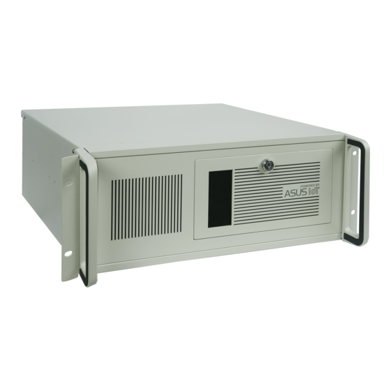
Page 12: Front Panel
Front panel The front panel includes the optical drive bays, power button, reset button, LED indicators and several I/O ports. Cabinet cover. Use the key to lock or unlock the cabinet cover. Reset button. Press this button to reset the system. Power button. -
Page 13: Rear Panel
Use a chassis with HD audio module in the front panel to support a 7.1-channel audio output. USB 3.2 Gen 2 (up to 10Gbps) ports (teal blue, Type-A). These 9-pin Universal Serial Bus (USB) ports are for USB 3.2 Gen 2 devices. ASUS EBE-4U... - Page 14 LAN (RJ-45) port. This port allows Gigabit connection to a Local Area Network (LAN) through a network hub. LAN port LED indications ACT/LINK LED Activity/Link LED Speed LED SPEED LED Status Description Status Description No link 10Mbps connection ORANGE Linked ORANGE 100Mbps connection BLINKING...
- Page 15 Air vents. These vents allow air ventilation. Serial ports (optional). These 9-pin COM ports are for pointing devices or other serial devices. Power connector. Plug the power cord to this connector. RATING: 115/230Vac, 50/60Hz, 6A/3A (WW) 115Vac, 60Hz, 6A (TW) 220Vac, 50Hz, 3A (China) ASUS EBE-4U...
-
Page 16: Internal Components
The illustration below is the internal view of the system when you remove the chassis cover and the power supply unit. The installed components are labeled for your reference. Front panel cover ASUS motherboard 5.25-inch optical drive bays 2 x PCI Express 3.0/2.0 x16 slots (x16 mode) 3.5-inch drive bay... - Page 17 Chapter 2 This chapter provides details about the motherboard that comes with the system. This chapter includes the motherboard layout, jumper settings, and connector locations.
-
Page 18: Chapter 2 Motherboard Information
Before you proceed Take note of the following precautions before you install motherboard components or change any motherboard settings. CAUTION! • Unplug the power cord from the wall socket before touching any component. • Before handling components, use a grounded wrist strap or touch a safely grounded object or a metal object, such as the power supply case, to avoid damaging them due to static electricity. -
Page 19: Motherboard Layout
3052 2242 3042 ASM1480 PCIEX4_2 NANO_SIM PCIEX16_2 Intel ® Q470E PCIEX4_3 1083 128Mb BIOS SPDIF_OUT Super DIS_ME PCI_1 BUZZER WDT_EN LPC_DEBUG CLRTC 2242 AT_ATX_SEL PCI_2 SATA6G_6 COM2_SEL SATA6G_5 SPEAKER USB1011 AAFP CHASSIS F_PANEL COM2 COM3 COM4 COM5 COM6 ASUS EBE-4U... - Page 20 Connectors/Jumpers/Slots Page COM RING/+5V/+12V selection jumper (6-pin COM1_SEL) 2-11 EATX Power connectors (24-pin EATXPWR, 8-pin EATX12V) 2-16 CPU and Chassis Fan headers (4-pin CPU_FAN, 4-pin CHA_FAN1/2/3) 2-16 Intel LGA1200 CPU socket ® M.2 socket 3 (M.2_PCH_(SKT3)) 2-17 DDR4 DIMM slots 2-10 USB 2.0 connectors / header (USB_INTERNAL_12, USB_INTERNAL_13, 2-17...
-
Page 21: Central Processing Unit (Cpu)
Return Merchandise Authorization (RMA) requests only if the motherboard comes with the cap on the LGA1200 socket. • The product warranty does not cover damage to the socket contacts resulting from incorrect CPU installation/removal, or misplacement/loss/ incorrect removal of the PnP cap. ASUS EBE-4U... -
Page 22: Cpu Installation
2.3.1 CPU installation Chapter 2: Motherboard information... - Page 23 ASUS EBE-4U...
- Page 24 CAUTION! Apply the Thermal Interface Material to the CPU heatsink and CPU before you install the heatsink and fan if necessary. To install the CPU heatsink and fan assembly Chapter 2: Motherboard information...
- Page 25 To uninstall the CPU heatsink and fan assembly ASUS EBE-4U...
-
Page 26: System Memory
System memory This motherboard comes with four Double Data Rate 4 (DDR4) Dual Inline Memory Module (DIMM) sockets. The figure below illustrates the location of the DDR4 DIMM sockets: Channel Sockets Channel A DIMM_A1 & DIMM_A2* Channel B DIMM_B1 & DIMM_B2* Recommended memory configuration DIMM_A1 DIMM_A2*... -
Page 27: Jumpers
This jumper allows you to enable or disable the Intel ME function. Set this ® jumper to pins 1-2 to enable (default) the Intel ME function and to pins 2-3 to ® disable it. Connector type HEADER 1x3p, 2.54mm pitch, S/T ASUS EBE-4U 2-11... - Page 28 AT/ATX Mode selection jumper (3-pin AT_ATX_SEL) AT_ATX_SEL High Active Low Active (Default) Pins 1-2 (Default) High Avtive Low Active Connector type HEADER 1x3p, 2.54mm pitch, S/T WDT Enable jumper (2-pin WDT_EN) A watchdog timer is an electronic timer that is used to detect and recover from computer malfunctions.
- Page 29 Hold down the <Del> key during the boot process and enter BIOS Setup to re-enter data. NOTE: If the steps above do not help, remove the onboard battery and move the jumper again to clear the CMOS RTC RAM data. After clearing the CMOS, reinstall the battery. ASUS EBE-4U 2-13...
-
Page 30: Connectors
Connectors EATX power connectors (24-pin EATXPWR, 8-pin EATX12V) Correctly orient the ATX power supply plugs into these connectors and push down firmly until the connectors completely fit. EATX12V EATXPWR +3 Volts +12 Volts +5 Volts PIN 1 +12 Volts +5 Volts +5V Standby +5 Volts -5 Volts... - Page 31 • This socket supports M Key and 2242/2260/2280 storage devices. USB 2.0 connectors / header ( USB_INTERNAL_12, USB_INTERNAL_13, USB1011 These Universal Serial Bus (USB) ports / header are for USB 2.0 devices. USB_INTERNAL_12 USB_INTERNAL_13 USB1011 PIN 1 ASUS EBE-4U 2-15...
- Page 32 USB 3.2 Gen 1 header (20-1 pin U32G1_67) Connect a USB 3.2 Gen 1 module to this connector for additional USB 3.2 Gen 1 front or rear panel ports. This connector complies with USB 3.2 Gen 1 specifications and provides faster data transfer speeds of up to 5 Gbps, faster charging time for USB-chargeable devices, optimized power efficiency, and backward compatibility with USB 2.0.
- Page 33 These connectors connect to Serial ATA 6.0 Gb/s hard disk drives or an optical drive via Serial ATA 6.0 Gb/s signal cables. SATA6G_1 RSATA_TXP SATA6G_2 RSATA_TXN SATA6G_3 RSATA_RXN RSATA_RXP SATA6G_4 SATA6G_6 SATA6G_5 Connector type WAFER HD 7p, 1.27mm pitch ASUS EBE-4U 2-17...
- Page 34 M.2 Wi-Fi This socket connects to an M.2 Wi-Fi device. M.2(WIFI) +3VSB_WIFI +3VSB_WIFI S_USB_PP10_CN S_USB_PN10_CN S_CNV_RF_RESET_N S_CNV_WR_D1_N S_CNV_WR_D1_P S_XTAL_CLKREQ S_CNV_WR_D0_N PIN 1 S_CNV_WR_D0_P S_CNV_BRI_RSP S_CNV_WR_CLK_N S_CNV_WR_CLK_P S_CNV_RGI_DT S_CNV_RGI_RSP S_CNV_BRI_DT S_WIFI_TXP_C S_WIFI_TXN_C CL_RST# CL_DATA CL_CK S_WIFI_RXP CNVI_GNSS_R S_WIFI_RXN MFUART2_TXD_R MFUART2_RXD_R CK_WIFI_CLKP S_SUSCLK_R CK_WIFI_CLKN S_PLTRST#...
- Page 35 This connector is for a general purpose input/output module which allows you to customize the digital signal input/output. GPIO_CON +5VSB GPIO8 GPIO7 GPIO6 GPIO5 GPIO4 GPIO3 GPIO2 GPIO1 PIN 1 Connector type WAFER HD 2x5p, 2.0mm pitch, S/T ASUS EBE-4U 2-19...
- Page 36 12. System Panel header (10-1 pin F_PANEL) This header supports several chassis-mounted functions. +PWR_LED PWR_BTN F_PANEL PIN 1 +HDD_LED RESET Connector type Header 2x5p, K10, 2.54mm pitch • System power LED (2-pin +PWR_LED) This 2-pin header is for the system power LED. Connect the chassis power LED cable to this header.
- Page 37 HEADER 4p, K2, 2.54mm pitch 14. Speaker header (4-pin SPEAKER) The 4-pin header is for the chassis-mounted system warning speaker. The speaker allows you to hear system beeps and warnings. SPEAKER PIN 1 Connector type HEADER 1x4p, 2.54mm pitch, S/T ASUS EBE-4U 2-21...
- Page 38 • Scan the QR code to view the meaning of each debug code. • Debug codes are only available for ASUS LPC debug card. • Contact your region sales representative for LPC debug header ordering. 16. COM Port headers (10-1 pin COM2, COM3, COM4, COM5, COM6) These headers are for serial (COM) ports.
- Page 39 • If you want to connect a high-definition front panel audio module to this connector, set the HD Audio Controller item in the BIOS Setup to [Enabled]. ASUS EBE-4U 2-23...
- Page 40 Digital audio connector (4-1 pin SPDIF_OUT) This connector is for an additional Sony/Philips Digital Interface (S/PDIF) port. Connect the S/PDIF Out module cable to this connector, then install the module to a slot opening at the back of the system chassis. SPDIF_OUT PIN 1 Connector type...
- Page 41 Chapter 3 This chapter provides a detailed guide to navigating and setting up the BIOS.
-
Page 42: Chapter 3 Bios Setup
Always shut down the system properly from the operating system. IMPORTANT! • Visit the ASUS website at www.asus.com to download the latest BIOS file for this motherboard. • The default BIOS settings for this motherboard apply to most working conditions and ensures optimal performance. -
Page 43: Main Menu
This item allows you to configure Management Engine Technology parameters. TPM Device Selection Allows you to select TPM device. [PTT] Enables PTT in SkuMgr. [dTPM] Disables PTT in SkuMgr. When PTT is disabled, all data saved on it will be lost. ASUS EBE-4U... -
Page 44: Trusted Computing
3.3.2 Trusted Computing Security Device Support Allows you to enable or disable BIOS support for security device. Configuration options: [Disable] [Enable] The following items appear when a TPM device is installed on your motherboard. SHA-1 PCR Bank Configuration options: [Disabled] [Enabled] SHA256 PCR Bank Configuration options: [Disabled] [Enabled] SHA384 PCR Bank... -
Page 45: Cpu Configuration
Allows you to enable or disable Intel Speed Shift Technology support. When ® enabled, CPPC v2 interface allows hardware controlled P-state. Configuration options: [Disabled] [Enabled] The following item appears only when Intel(R) SpeedStep or Intel(R) Speed Shift is available and enabled. ASUS EBE-4U... -
Page 46: Graphics Configuration
Turbo Mode Configuration options: [Disabled] [Enabled] C states Allows you to enable or disable CPU Power Management. Configuration options: [Disabled] [Enabled] The following item appears only when you set C states to [Enabled]. Enhanced C-states Allows you to enable or disable C1E. CPU will switch to minimum speed when all cores enter C-state. - Page 47 [Enabled] [Auto] Max Link Speed Allows you to configure PEG 0:1:2 Max Speed. Configuration options: [Auto] [Gen1] [Gen2] [Gen3] Max Link Width Allows you to force PEG link to restrain to X1/2. Configuration options: [Auto] [Force X1] [Force X2] ASUS EBE-4U...
- Page 48 ASPM This item allows you to control ASPM support for the PEG 2, and this has no effect if PGE is not the currently active device. Configuration options: [Disabled] [Auto] [ASPM L0s] [ASPM L1] [ASPM L0sL1] PCIEX4_1 (X2) Allows you to configure the PCI Express root port settings. PCIEX4_1(X2) Allows you to enable or disable the PCI Express Root Port.
-
Page 49: Amt Configuration
Screen or pressing 2 to initiate a remote connection. Configuration options: [Disabled] [Enabled] Network Access must be activated from MEBx Setup for this screen to be dispalyed. Unconfigure ME Allows you to unconfigure ME by resetting the MEBx password to default. Configuration options: [Disabled] [Enabled] ASUS EBE-4U... -
Page 50: Csm Configuration
3.3.7 CSM Configuration CSM Support Allows you to enable or disable CSM (Compatibility Support Module) Support. Configuration options: [Disabled] [Enabled] The following items appear only when you set CSM Support to [Enabled]. GateA20 Active Configuration options: [Upon Request] [Always] [Upon Request] GA20 can be disabled using BIOS services. - Page 51 [Auto] [IO=2F0h; IRQ=7;] [IO=3E8h; IRQ=3, 4, 5, 6, 7, 9, 10, 11, 12;] [IO=2E8h; IRQ=3, 4, 5, 6, 7, 9, 10, 11, 12;] [IO=2F0h; IRQ=3, 4, 5, 6, 7, 9, 10, 11, 12;] [IO=2E0h; IRQ=3, 4, 5, 6, 7, 9, 10, 11, 12;] ASUS EBE-4U 3-11...
-
Page 52: Serial Console Redirection
Parallel Port Configuration This item allows you to set parameters of Parallel Port (LPT/LPTE). Parallel Port Allows you to enable or disable the serial port (COM).Configuration options: [Disabled] [Enabled] Change Settings Allows you to select an optimal setting for Super IO Device. Configuration options: [Auto] [IO=378h;... - Page 53 Allows you to select a COM port to display redirection of Legacy OS and Legacy OPROM Messages. Configuration options: [COM1] [COM2] [COM3] [COM4] [COM5] [COM6] [COM7(Pci Bus0,Dev0,Func0) (Disabled)] Resolution This allows you to set the number of rows and columns supported on the Legacy OS. ASUS EBE-4U 3-13...
-
Page 54: Sata And Rst Configuration
Configuration options: [80x24] [80x25] Redirect After POST Configuration options: [Always Enable] [BootLoader] [Always Enable] Legacy Console Redirection is enabled for Legacy OS. [BootLoader] Legacy Console Redirection is disabled before booting to Legacy OS. 3.3.10 SATA And RST Configuration This item allows you to configure SATA device options settings. SATA Controller(s) Allows you to enables or disables the onboard SATA device. -
Page 55: Network Stack Configuration
Use either +/- or numeric keys to set the value for wait time (in seconds) to press ESC key to abort the PXE boot. Media detect count Use either +/- or numeric keys to set the value for number of times the presence of media will be checked. ASUS EBE-4U 3-15... -
Page 56: Usb Configuration
3.3.12 USB Configuration Legacy USB Support Configuration options: [Enabled] [Disabled] [Auto] [Enabled] Enables Legacy USB support. [Disabled] Keeps USB devices available only for EFI applications. [Auto] Allows the system to detect the presence of USB devices at startup. If any USB device(s) is detected, the USB controller legacy mode is enabled. -
Page 57: Nvme Configuration
This item allows you to configure APM (Advanced Power Management) settings. ErP Ready Allows BIOS to switch off some power at S5 to get the system ready for ErP requirement. When set to [Enabled], all other PME options will be switched off. Configuration options: [Disabled] [Enabled] ASUS EBE-4U 3-17... - Page 58 Restore AC Power Loss Allows you to select AC power state when power is re-applied after a power failure. Configuration options: [S5 State] [S0 State] Power On By PCIE Allows you to enable or disable the Wake-on-LAN function of the onboard LAN controller or other installed PCIe LAN cards.
-
Page 59: Watchdog Timer
Allows you to set the value of temperature1 / 2 / 3 / 4. FD/RPM 1 ~ FD/RPM 4 Allows you to set the value of Fan Duty/PRM 1 / 2 / 3 / 4 when temperature is T1 / 2 / 3 / 4. ASUS EBE-4U 3-19... -
Page 60: Security Menu
CPU Fan Setting Temperature 1 ~ Temperature 1 Allows you to set the value of temperature1 / 2 / 3 / 4. FD/RPM 1 ~ FD/RPM 4 Allows you to set the value of Fan Duty/PRM 1 / 2 / 3 / 4 when temperature is T1 / 2 / 3 / 4. -
Page 61: Secure Boot
[Enabled] Setup Prompt Timeout Allows you to set the number of seconds to wait for setup activation key. 65535(0xFFFF) means indefinite waiting. Bootup NumLock State Allows you to select the keyboard NumLock state. Configuration options: [On] [Off] ASUS EBE-4U 3-21... -
Page 62: Exit Menu
Quiet Boot Configuration options: [Disabled] [Enabled] Fast Boot Allows you to enable or disable boot with initialization of a minimal set of devices required to launch active boot option. This has no effect for BBS boot options. Configuration options: [Disabled] [Enabled] [Enabled] Select to accelerate the boot speed. - Page 63 Restore User Defaults Allows you to restore the User Defaults to all the setup options. Boot Override UEFI: Generic-SD/MMC, Partition 1 When you select this option, a confirmation window appears. Select Yes to save configuration and reset. ASUS EBE-4U 3-23...
- Page 64 3-24 Chapter 3: BIOS setup...
-
Page 65: Appendix
Appendix Notices FCC Compliance Information Responsible Party: Asus Computer International Address: 48720 Kato Rd., Fremont, CA 94538, USA Phone / Fax No: (510)739-3777 / (510)608-4555 This device complies with part 15 of the FCC Rules. Operation is subject to the following two conditions: (1) This device may not cause harmful interference, and (2) this device must accept any interference received, including interference that may cause undesired operation. - Page 66 CAN ICES-003(B)/NMB-003(B) VCCI: Japan Compliance Statement Class B ITE KC: Korea Warning Statement HDMI Compliance Statement The terms HDMI, HDMI High-Definition Multimedia Interface, and the HDMI Logo are trademarks or registered trademarks of HDMI Licensing Administrator, Inc. EBE-4U...
- Page 67 ASUS Recycling/Takeback Services ASUS recycling and takeback programs come from our commitment to the highest standards for protecting our environment. We believe in providing solutions for you to be able to responsibly recycle our products, batteries, other components as well as the packaging materials.
- Page 68 UE è disponibile asus.com/support all’indirizzo: www.asus.com/support Português A ASUSTeK Computer Inc. declara que este Русский Компания ASUS заявляет, что это устройство dispositivo está em conformidade com os requisitos essenciais соответствует основным требованиям и другим e outras disposições relevantes das Diretivas relacionadas. Texto соответствующим...
-
Page 69: Service And Support
Service and Support Visit our multi-language website at https://www.asus.com/support/ Appendix...