Table of Contents
Advertisement
Quick Links
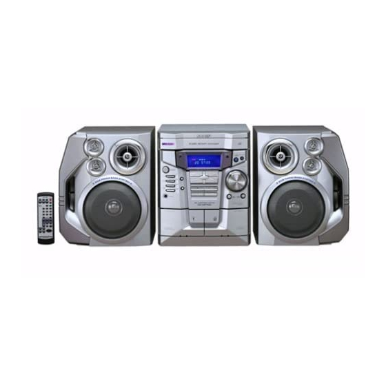
Illustration: CD-MP700
IMPORTANT SERVICE NOTES ........................................................................................................................................ 2
SPECIFICATIONS ............................................................................................................................................................. 2
NAMES OF PARTS ........................................................................................................................................................... 3
DISASSEMBLY .................................................................................................................................................................. 5
REMOVING AND REINSTALLING THE MAIN PARTS ..................................................................................................... 8
ADJUSTMENT ................................................................................................................................................................... 9
BLOCK DIAGRAM ........................................................................................................................................................... 13
SCHEMATIC DIAGRAM / WIRING SIDE OF P.W.BOARD ............................................................................................. 16
VOLTAGE ........................................................................................................................................................................ 34
NOTES ON SCHEMATIC DIAGRAM .............................................................................................................................. 35
TYPES OF TRANSISTOR AND LED ............................................................................................................................... 35
WAVEFORMS OF CD CIRCUIT ...................................................................................................................................... 36
TROUBLESHOOTING ..................................................................................................................................................... 37
FUNCTION TABLE OF IC ................................................................................................................................................ 41
FL DISPLAY ..................................................................................................................................................................... 52
REPLACEMENT PARTS LIST/EXPLODED VIEW
All manuals and user guides at all-guides.com
SERVICE MANUAL
CONTENTS
SHARP CORPORATION
MINI COMPONENT SYSTEM
CD-MP700
MODEL
CD-MP700 Mini Component System consisting of CD-MP700
(main unit) and CP-E700 (speaker system).
MINI COMPONENT SYSTEM
CD-MP77
MODEL
CD-MP77 Mini Component System consisting of CD-MP77
(main unit) and CP-E77 (speaker system).
• In the interests of user-safety the set should be restored to its
original condition and only parts identical to those specified be
used.
This document has been published to be used
for after sales service only.
The contents are subject to change without notice.
CD-MP700/CD-MP77
No. S1308CDMP700/
Page
Advertisement
Table of Contents

Related Manuals for Sharp CD-MP700


Summary of Contents for Sharp CD-MP700
-
Page 1: Table Of Contents
All manuals and user guides at all-guides.com CD-MP700/CD-MP77 SERVICE MANUAL No. S1308CDMP700/ MINI COMPONENT SYSTEM CD-MP700 MODEL CD-MP700 Mini Component System consisting of CD-MP700 (main unit) and CP-E700 (speaker system). MINI COMPONENT SYSTEM Illustration: CD-MP700 CD-MP77 MODEL CD-MP77 Mini Component System consisting of CD-MP77 (main unit) and CP-E77 (speaker system). -
Page 2: Important Service Notes
All manuals and user guides at all-guides.com CD-MP700/CD-MP77 IMPORTANT SERVICE NOTES BEFORE RETURNING THE AUDIO PRODUCT (Fire & Shock Hazard) Before returning the audio product to the user, perform the following safety checks. 1. Inspect all lead dress to make certain that leads are not... -
Page 3: Names Of Parts
All manuals and user guides at all-guides.com CD-MP700/CD-MP77 NAMES OF PARTS CD-MP700/CD-MP77 Front panel 1. Disc Tray 2. Timer Set Indicator 3. Memory/Set Button 4. Power On/Stand-by Button 5. Clock Button 6. Timer/Sleep Button 7. Tuning and Time Up Button 8. - Page 4 All manuals and user guides at all-guides.com CD-MP700/CD-MP77 CD-MP700/CD-MP77 Remote control 1. Remote Control Transmitter 2. Disc Number Select Buttons 3. Program Clear Button 4. Disc Memory Button 5. Disc Track Down or Fast Reverse, Tape 2 Rewind Button 6. Disc Pause Button 7.
-
Page 5: Disassembly
All manuals and user guides at all-guides.com CD-MP700/CD-MP77 DISASSEMBLY Caution on Disassembly CD-MP700/CD-MP77 Follow the below-mentioned notes when disassembling Top Cabinet the unit and reassembling it, to keep it safe and ensure excellent performance: Front (A1)x2 Panel 1. Take cassette tape and compact disc out of the unit. - Page 6 All manuals and user guides at all-guides.com CD-MP700/CD-MP77 (L1)x3 Loading Tray (E2)x2 (E3)x1 (E1)x3 ø3x6mm (F3)x1 Front Panel (E2)x1 (F2)x1 (E4)x1 Power PWB Transformer Headphones (L1)x3 Main PWB Figure 6-4 (F2)x1 (F1)x1 ø3x10mm (M1)x2 Figure 6-1 ø3x10mm (G3)x1 Loading Front Panel...
- Page 7 All manuals and user guides at all-guides.com CD-MP700/CD-MP77 CP-E700/CP-E77 REMOVAL PROCEDURE FIGURE STEP Passive Radiator 1. Screw ...... (A1) x4 2. Side Panel ....(A2) x1 Super Tweeter 3. Screw ...... (A3) x4 Woofer 1. Front Panel ..... (B1) x1 Speaker Box 2.
-
Page 8: Removing And Reinstalling The Main Parts
All manuals and user guides at all-guides.com CD-MP700/CD-MP77 REMOVING AND REINSTALLING THE MAIN PARTS TAPE MECHANISM SECTION TAPE 2 Perform steps 1 to 6 and 8 of the disassembly method to Clutch Ass'y remove the tape mechanism. Record/Playback Head How to remove the record/playback and erase heads (TAPE 2) (See Fig. -
Page 9: Adjustment
All manuals and user guides at all-guides.com CD-MP700/CD-MP77 CD MECHANISM SECTION Loading Loading Perform steps 1, 2, 3, 10, 11,12 and 13 of the disassembly Motor PWB Motor method to remove the CD mechanism. Loading Tray How to remove the loading motor (See Fig. - Page 10 All manuals and user guides at all-guides.com CD-MP700/CD-MP77 TUNER SECTION CD SECTION fL: Low-range frequency • Adjustment fH: High-range frequency Since this CD system incorporates the following automatic • • • • • AM IF/RF adjustment functions, readjustment is not needed when replacing the pickup.
- Page 11 All manuals and user guides at all-guides.com CD-MP700/CD-MP77 TEST MODE • Setting the test mode Any one of test mode can be set by pressing several keys as follows. <X-BASS> + <CD> + <POWER> TEST: CD operation test. Function: -CD test mode.
- Page 12 All manuals and user guides at all-guides.com CD-MP700/CD-MP77 Standard Specification of Stereo System Error Message Display Contents Error Contents DISPLAY Notes Pickup Mechanism Error. 'ER-CD**' 01: PU-IN SW Detection NG. CD Changer Mechanism Error. 'ER-CD**' 10: Changer Error. 11: Initial Error.
-
Page 13: Block Diagram
All manuals and user guides at all-guides.com CD-MP700/CD-MP77 8 10 12 14 20 22 32 52 62 69 75 76 LRSY FSYNC ADDATA CMDOUT ADBCK INTB ADLRCK DVDD1 C2FIN DVDD2 CKIN(16M) LC78683E DVDD3 +3.3V CKOUT MP3 DECORDER DVDD4 DATAIN DVDD5... - Page 14 All manuals and user guides at all-guides.com CD-MP700/CD-MP77 AM LOOP ANTENNA IC301 ZD351 TA7358AP ANTENNA 5.1V FM FRONT END FM IF 10.7 MHz T302 CF303 BF301 X351 450 kHz CF351 456 kHz B.P.F T351 CF352 CNP301 AM IF FM RF L312...
- Page 15 All manuals and user guides at all-guides.com CD-MP700/CD-MP77 FL701 FL DISPLAY TO CD SECTION TAPE MECHANISM ASS'Y +B10 RX701 55 40 54 3 52 51 25 13 30 REMOTE SENSOR +B10 +B10 IC701 VLOAD AVDD IX0555AW SYSTEM SW701-SW707 SW711-SW718 MICROCOMPUTER...
-
Page 16: Schematic Diagram / Wiring Side Of P.w.board
All manuals and user guides at all-guides.com CD-MP700/CD-MP77 CNS601 BI601 R-CH FM SIGNAL R601 A_GND PLAYBACK SIGNAL L-CH R602 CD_GND RECORD SIGNAL CD_+B CD SIGNAL IC601 D_GND C653 LC75341 220P 220/ LD+7V VIDEO SIGNAL AUDIO PROCESSOR LD+7V C609 R605 1/50... - Page 17 All manuals and user guides at all-guides.com CD-MP700/CD-MP77 MAIN PWB-A1(1/3) R693 C602 C653 C601 0.022 220P 220/16 L-CH R691 C691 6.8K 390P JK690 AUX/VIDEO R690 C690 6.8K 390P R603 R-CH R692 C603 VREF 22/50 C608 C610 0.12 1/50 ROUT R606 R604 3.9K...
- Page 18 All manuals and user guides at all-guides.com CD-MP700/CD-MP77 C302 0.001 AM TRACKING C331 C330 0.047 C323 0.022 (UJ) C332 0.022 C338 0.001 T303 D301 DS1SS133 AM ANTENNA C342 D302 DS1SS133 0.022 VD301 T306 SVC348S C335 AM OSC. 560P R358 3.9K...
- Page 19 All manuals and user guides at all-guides.com CD-MP700/CD-MP77 MAIN PWB-A1 (2/3) C373 TP302 0.015 C371 1/50 R350 2.7K R358 C367 3.9K 1/50 C372 1/50 10 11 R352 R353 R355 T351 C357 3.3K 2.2/50 AM IF C356 0.001 R393 L352 C389 0.001...
- Page 20 All manuals and user guides at all-guides.com CD-MP700/CD-MP77 IC901 STK41242 – POWER AMP. L902 C913 3µH 100P C907 R903 100P Q903 KTC3199 GR R917 0.1(3W) ZD902 ZD903 R918 DZ12BSB DZ12BSB C917 1.5K 0.01(ML) C916 C918 R905 100/50 100/50 R919 R925...
- Page 21 All manuals and user guides at all-guides.com CD-MP700/CD-MP77 MAIN PWB-A1 (3/3) FM SIGNAL L902 3µH CNS971 199 GR R942 390(2W) M901 R943 390(2W) – FAN MOTOR R944 R945 1.5K 1.5K L1_OUT D912 R949 DS1SS133 HEADPHONES R1_OUT PWB-A3 R950 C931 R947...
- Page 22 All manuals and user guides at all-guides.com CD-MP700/CD-MP77 FL701 LED A PWB-A4 FL DISPLAY BI703 LED DRIVER +10V Q710 R794 KRC102 M 45 44 43 42 41 40 39 38 37 36 35 34 33 32 31 30 29 28 27 26 25 24 23 22 21 20 19 18 17 16 15 14 13 12 11...
- Page 23 All manuals and user guides at all-guides.com CD-MP700/CD-MP77 DISPLAY PWB-A2 18 17 16 15 14 13 12 11 10 9 R795 C701 1/50 C702 220/10 87 88 89 90 91 92 93 94 95 96 97 R763 –20dBATT R701 SUB_CE/DSA_STB...
- Page 24 All manuals and user guides at all-guides.com CD-MP700/CD-MP77 CD MP3 PWB-C 100P 0.022 100P 100P CD SIGNAL 100P 100P 100P 0.022 0.001 0.22/50 4.7K 2.2K 2.2K PICKUP UNIT 0.047 0.022 80 79 78 77 76 75 74 73 72 71 70 69 68 67 66 65 64...
- Page 25 All manuals and user guides at all-guides.com CD-MP700/CD-MP77 IX0542AW MP3 SUB MICROCOMPUTER 47/10 4.19 MHz 100K 0.01 0.022 2.2K 2.2K CNP7 0.001 MP3-RES SYS-DI SYS-DO CDEMPH SYS-CL SYS-CE INTB 2.2K AVDD MP3DI CD RES AVREF MP3DO CLAMP SW 1 2 3 4 5 6 7 8 9 10 11 0.01...
- Page 26 All manuals and user guides at all-guides.com CD-MP700/CD-MP77 MAIN PWB-A1 COLOR TABLE BROWN R374 C302 R378 R373 RD(R) X352 R372 ORANGE R388 C382 YELLOW R359 GREEN IC302 R376 C395 R379 C381 C387 R360 BLUE VIOLET C392 L351 R377 C394 C380...
- Page 27 All manuals and user guides at all-guides.com CD-MP700/CD-MP77 P30 4 - B P29 12 - E TO CD MP3 PWB TO DISPLAY PWB CNP6 CNP701A FFC701 R136 P33 10 - E CNS601 1 2 3 4 5 6 7 8...
- Page 28 All manuals and user guides at all-guides.com CD-MP700/CD-MP77 DISPLAY PWB-A2 LED B PWB-A5 SW722 RX701 FL70 EQUALIZER SW721 X-BASS/DEMO RD19 RD20 CNS704 R763 R701 C701 R702 C702 CNP704 XL701 CNS701 R705 R708 C721 C704 R709 C705 R710 R711 RD10 R712...
- Page 29 All manuals and user guides at all-guides.com CD-MP700/CD-MP77 LED B PWB-A4 FL701 BI703 CNS703 CNP703 IC701 R746 R751 R747 R735 R770 L701 R772 SW701 R734 3 2 1 R758 POWER R731 R749 R764 Q710 R732 C704 R730 R729 C705 R728...
- Page 30 All manuals and user guides at all-guides.com CD-MP700/CD-MP77 P28 1 - D P27 8 - A FROM DISPLAY PWB FROM MAIN PWB CNS701 CNS601 CNP7 CNP6 1 2 3 4 5 6 7 8 9 101112 1 2 3 4 5 6 7 8...
- Page 31 All manuals and user guides at all-guides.com CD-MP700/CD-MP77 35 30 65 70 75 45 50 55 CD MP3 PWB-C (TOP VIEW) Figure 31 WIRING SIDE OF P.W.BOARD (6/8) – 31 –...
- Page 32 All manuals and user guides at all-guides.com CD-MP700/CD-MP77 POWER PWB-B1 P27 12 - G P28 1 - E FROM MAIN PWB FROM DISPLAY PWB CNS801 FW701 R841 IC854 D853 CNP802 3 2 1 D801 D856 R844 10 9 8 7 6 5 4 3 2 1...
- Page 33 All manuals and user guides at all-guides.com CD-MP700/CD-MP77 P28 3 - G TAPE MECHANISM TO DISPLAY PWB ASSEMBLY CNP702 TAPE MECHANISM PWB-F FFC702 SOLENOID SOLENOID TAPE MOTOR CD LOADING MOTOR PWB-E TAPE 2 TAPE 1 RECORD/PLAYBACK PLAYBACK HEAD ERASE HEAD...
-
Page 34: Voltage
All manuals and user guides at all-guides.com CD-MP700/CD-MP77 VOLTAGE IC701 VOLTAGE VOLTAGE VOLTAGE VOLTAGE VOLTAGE VOLTAGE VOLTAGE VOLTAGE VOLTAGE 1.6 V 3.7 V 1.7 V 1.61 V 3.26 V 3.25 V 4.85 V 4.93 V 1.0 V 3.7 V 1.7 V 20.7 V... -
Page 35: Notes On Schematic Diagram
All manuals and user guides at all-guides.com CD-MP700/CD-MP77 NOTES ON SCHEMATIC DIAGRAM • Resistor: • The indicated voltage in each section is the one measured by Digital Multimeter between such a section and the chas- To differentiate the units of resistors, such symbol as K and M are used: the symbol K means 1000 ohm and the symbol sis with no signal given. -
Page 36: Waveforms Of Cd Circuit
All manuals and user guides at all-guides.com CD-MP700/CD-MP77 WAVEFORMS OF CD CIRCUIT Stopped Stopped 1999/04/07 09:51:15 CH1=500 mV CH3=500 mV 500 ms/div CH1=200 mV CH2=500 mV 500 ms/div DC 10:1 DC 10:1 (500 ms/div) DC 10:1 DC 10:1 (500 ms/div) -
Page 37: Troubleshooting
All manuals and user guides at all-guides.com CD-MP700/CD-MP77 TROUBLESHOOTING When the CD does not function When the CD section does not operate when the objective lens of the optical pickup is dirty, this section may not operate. Clean the objective lens, and check the playback operation. When this section does not operate even after the above step is taken, check the following items. - Page 38 All manuals and user guides at all-guides.com CD-MP700/CD-MP77 Stopped (1) Focus-HF system check. CH1=500 mV CH3=500 mV 500 ms/div DC 10:1 DC 10:1 (500 ms/div) NORM:20 kS/s Although a CD is inserted and the cover is closed, "NO DISC" is displayed.
- Page 39 All manuals and user guides at all-guides.com CD-MP700/CD-MP77 (2) Tracking system check. Check the TE waveform at pin 15 on IC1. The tracking servo is not activated. If the waveform shown in Figure 39-1 appears and soon after Check the peripheral circuits at pins 14, 15 and 20 on IC1, and NO DISC appears ? CNS1A/B.
- Page 40 All manuals and user guides at all-guides.com CD-MP700/CD-MP77 (4) PLL system check. Stopped 1999/04/05 17:33:17 CH1=500 mV CH3=1 V CH4=1 V 500 ms/div DC 10:1 DC 10:1 DC 10:1 (500 ms/div) NORM:20 kS/s When a disc is loaded, start play operation.
-
Page 41: Function Table Of Ic
All manuals and user guides at all-guides.com CD-MP700/CD-MP77 FUNCTION TABLE OF IC IC1 VHiLC78646E-1: CD Servo (LC78646E) (1/2) Terminal Name Input/Output Setting in Reset Function Pin No. SLCO Output — Control output. For slice level SLCIST Input — Resistor connection terminal for SLCO output current setting. - Page 42 All manuals and user guides at all-guides.com CD-MP700/CD-MP77 IC1 VHiLC78646E-1: CD Servo (LC78646E) (2/2) Terminal Name Input/Output Setting in Reset Pin No. Function RVSS — — GND for Right channel. Must be connected to 0 V. Right channel RCHO Output LVDD /2 Right channel output.
- Page 43 All manuals and user guides at all-guides.com CD-MP700/CD-MP77 IC1 VHiLC78646E-1: CD Servo (LC78646E) 75 74 72 71 69 68 66 65 63 62 SLCO DATA SLCIST EFMIN LRCK ASDFIN RFVDD ASDACK RFVSS ASLRCK FIN1 16MOUT FIN2 EFLG TIN1 TIN2 XVSS...
- Page 44 All manuals and user guides at all-guides.com CD-MP700/CD-MP77 IC3 VHiLC78683E-1: MP3 Decoder (LC78683E) (1/2) Pin No. Terminal Name Input/Output Function LRSY Input CD L/R clock input. ADDATA Output Audio data output. ADBCK Output Audio bit clock output. ADLRCK Output Audio L/R clock output.
- Page 45 All manuals and user guides at all-guides.com CD-MP700/CD-MP77 IC3 VHiLC78683E-1: MP3 Decoder (LC78683E) (2/2) Pin No. Terminal Name Input/Output Function DVDD4 Input I/O digital supply pin. — GND ground pin. ADRS7 Output DRAM address output 7. ADRS6 Output DRAM address output 6.
- Page 46 All manuals and user guides at all-guides.com CD-MP700/CD-MP77 IC3 VHiLC78683E-1: MP3 Decoder (LC78683E) LRSY ADRS0 ADDATA ADRS1 ADBCK ADRS2 ADLRCK ADRS3 C2FIN ADRS4 TEST1 ADRS5 CKIN ADRS6 ADRS7 CKOUT TEST2 DVDD4 LC78683E DVDD1 ADRS8 ADRS9 SBSY ADRS10 SFSY ADRS11 SBCK...
- Page 47 All manuals and user guides at all-guides.com CD-MP700/CD-MP77 IC4 VHiLC32V4265B: 4M D-RAM (LC32V4265B) Pin No. Terminal Name Function Power supply. MDATA0-MDATA3 Data I/O. Power supply. 7-10 MDATA4-MDATA7 Data I/O. 11*-14* N.C. Not used. Write enable. RASB Low address strobe. N.C.
- Page 48 All manuals and user guides at all-guides.com CD-MP700/CD-MP77 IC5 RH-iX0542AWZZ: MP3 Sub Microcomputer (IX0542AW) Pin No. Terminal Name Function P60/ANI0-P67ANI7 Port 6. Analog input. AVSS Analog ground. 10,11 P10, P11 Port 1 P30/INTP0/TI81/CPT90 Port 3. Interrupt from peripherals. Timer input. Capture trigger input.
- Page 49 All manuals and user guides at all-guides.com CD-MP700/CD-MP77 IC601 VHiLC75341/-1: Audio Processor (LC75341) LOUT ROUT LBASS RBASS LTRE RTRE LSEL0 RSEL0 R1 R2 24 23 22 21 20 19 18 17 16 15 14 13 LC75341 10 11 12 Figure 49 BLOCK DIAGRAM OF IC...
- Page 50 All manuals and user guides at all-guides.com CD-MP700/CD-MP77 IC701 RH-iX0555AWZZ: System Microcomputer (IX0555AW) (1/2) Pin No. Port Name Terminal Name Input/Output Function Input (+) Power supply. -20dBATT Output -20dB Attenuator. SUB_CE Output MP3 sub microcomputer. T_BIAS Output Tape record bias.
- Page 51 All manuals and user guides at all-guides.com CD-MP700/CD-MP77 IC701 RH-iX0555AWZZ: System Microcomputer (IX0555AW) (2/2) Pin No. Port Name Terminal Name Input/Output Function P120 O/C SW Input CD OPEN/CLOSE SW. P117 MIC SW Input Mic switch input. P116 KARA_LATCH Output Karaoke latch. (When not used. Connect to 0 V.)
-
Page 52: Fl Display
All manuals and user guides at all-guides.com CD-MP700/CD-MP77 FL DISPLAY FL701 VVKNA09SS29-1 GRID ASSIGNMENT X-BASS REC ST SLEEP TP TI PTYIPTY MHz TA MEMORY h j k (1G~8G) ANODE CONNECTION X-BASS PTYI MEMORY PRO LOGIC SLEEP – 52 –... - Page 53 All manuals and user guides at all-guides.com CD-MP700/CD-MP77 PARTS GUIDE MINI COMPONENT SYSTEM CD-MP700 MODEL CD-MP700 Mini Component System consisting of CD-MP700 (main unit) and CP-E700 (speaker system). MINI COMPONENT SYSTEM CD-MP77 MODEL CD-MP77 Mini Component System consisting of CD-MP77 (main unit) and CP-E77 (speaker system).
- Page 54 All manuals and user guides at all-guides.com CD-MP700/CD-MP77 PRICE PRICE DESCRIPTION PARTS CODE DESCRIPTION PART CODE RANK RANK TRANSFORMERS CD-MP700/CD-MP77 1 PT801 RTRNP0470AWZZ J BD Power INTEGRATED CIRCUITS 1 PT841 RTRNP0483AWZZ J AL Power T301 RCILB0065AWZZ AC OSC,FM VHILC78646E-1 AY CD Servo,LC78646E...
- Page 55 All manuals and user guides at all-guides.com CD-MP700/CD-MP77 PRICE PRICE DESCRIPTION PART CODE PARTS CODE DESCRIPTION RANK RANK AA 0.01 µF,16V AB 2.2 µF,50V,Electrolytic VCKYCY1CB103K C364 VCEAZA1HW225M J AB 0.1 µF,16V AA 0.022 µF,50V VCKYCY1CB104K C365 VCKZPA1HF223Z AB 47 µF,10V,Electrolytic AA 0.001 µF,50V...
- Page 56 All manuals and user guides at all-guides.com CD-MP700/CD-MP77 PRICE PRICE DESCRIPTION PARTS CODE DESCRIPTION PART CODE RANK RANK AA 0.01 µF,50V,Mylar C919 VCQYKA1HM103K J R132,133 VRD-MN2BD101J AA 100 ohm,1/8W AN 3300 µF,71V,Electrolytic C920 RC-EZ0029AWZZ R134,135 VRD-MN2BD103J AA 10 kohm,1/8W AE 4700 µF,35V,Electrolytic...
- Page 57 All manuals and user guides at all-guides.com CD-MP700/CD-MP77 PRICE PRICE DESCRIPTION PART CODE PARTS CODE DESCRIPTION RANK RANK R721 VRD-ST2CD102J AA 1 kohm,1/6W R961 VRD-MN2BD1R0J AA 1 ohm,1/8W R722 VRD-MN2BD102J AA 1 kohm,1/8W RD01 VRD-ST2CD681J AA 680 ohms,1/6W R724 VRD-MN2BD102J...
- Page 58 92LSWICHT1663T J AC Switch,Key Type [Open/Close] GCAB-1197AWZZ AM Loading Tray SW724 92LSWICHT1663T J AC Switch,Key Type [Disc Skip] GCAB-1215AWSA AT Top Cabinet [For CD-MP700] WTM701 QCNCW019FAWZZ J AB Holder,Flat Wire,6Pin GCAB-1215AWSB AR Top Cabinet [For CD-MP77] WTM801,802 QCNCW015DAWZZ J AB Holder,Flat Wire,4Pin...
- Page 59 All manuals and user guides at all-guides.com CD-MP700/CD-MP77 PRICE PRICE DESCRIPTION PART CODE PARTS CODE DESCRIPTION RANK RANK XJBSD30P10000 AA Screw,ø3×10mm PFLT-0046AWZZ AC Felt XEBSD30P12000 AA Screw,ø3×12mm QCNWN2483AWZZ J AQ Speaker Cord Ass’y LX-EZ0010AWFD AA Screw,Special (with Capacitor C1,2) LX-JZ0044AWFF AB Screw,ø3×10mm...
- Page 60 All manuals and user guides at all-guides.com CD-MP700/CD-MP77 CD-MP700/CD-MP77 306-2 306-1 306-3 703x2 305x2 PWB-D Figure 7 CD MECHANISM EXPLODED VIEW – 7 –...
- Page 61 All manuals and user guides at all-guides.com CD-MP700/CD-MP77 CD-MP700/CD-MP77 BELT CONNECTION 202-1 614x2 FF/REW Tape FF/REW PWB-A1 ROLLER Motor ROLLER ASS'Y ASS'Y 604x2 FLYWHEEL FLYWHEEL ASS'Y ASS'Y MAIN BELT TAPE2 TAPE1 614x3 IC851 Silicon IC852 Grease 601x10 IC853 601x2 615x3...
- Page 62 All manuals and user guides at all-guides.com CD-MP700/CD-MP77 CD-MP700/CD-MP77 602x2 620x2 MECHANISM 602x2 PWB-E PWB-C 619x2 Figure 9 CABINET EXPLODED VIEW (2/2) – 9 –...
- Page 63 All manuals and user guides at all-guides.com CD-MP700/CD-MP77 CP-E700/CP-E77 SP5, 6 SUPER TWEETER SP7, SUPER TWEETER SP5, SP3, 4 SUPER TWEETER TWEETER SP3, Capacitor SP7, 8 TWEETER 2.2 µF, Capacitor SUPER TWEETER 2.2 µF, 100 V (N.P.) 100 V (N.P.)
-
Page 64: Packing Of The Set
Feature Label [Tape2] 92LBAG1460C1 Polyethylene Bag, Accessories AM/FM Loop Antenna Operation Manual Quick Guide Remote Control SPAKC1566AWZZ [For CD-MP700] SPAKC1567AWZZ [For CD-MP77] Packing Case Not Replacement Item © COPYRIGHT 2003 BY SHARP CORPORATION SHARP CORPORATION ALL RIGHTS RESERVED. AV Systems Group...