
Related Manuals for ABB SureWave SFC


Summary of Contents for ABB SureWave SFC
- Page 1 –– STATIC F REQ UEN CY CO NV ERTER SureWave SFC™ User Manual © Copyright 2021 ABB, All rights reserved.
- Page 2 ABO U T T H IS D O C UM E NT –– ABB’s SureWave is the new generation of Static Frequency Converter (SFC) allows the connection of 60 Hz powered equip- ment to a 50 Hz supply network and 50 Hz powered equipment to a 60 Hz supply network.
-
Page 3: About This Document
Control and adjustments This manual does not claim to cover all variations and details of the SureWave SFC, nor to con- sider all eventualities that may arise during the operation of the product. Installation, commissioning, and maintenance of the product are covered elsewhere. If the... - Page 4 The manual addresses personnel who are responsible for operation and maintenance of the SureWave SFC. The personnel must carry out the listed tasks in a manner that does not cause physical harm or danger, and that ensures the safe and reliable functioning of the product.
- Page 5 ABO U T T H IS D O C UM E NT 1.1.6 Responsibilities of the user It is the responsibility of those in charge of the SureWave SFC to ensure that each person involved in the installation, operation or maintenance of the product has received the appropriate training...
- Page 6 The SFC and accessories are identified by the type code printed on the rating label. The label is located on the back of the PE120-1 enclosure door. The Label provides information on the SureWave SFC rated voltage, frequency, rated current and auxiliary power supply.
-
Page 7: Abbreviations & Terms
Abbreviations & Terms The following table lists terms and abbreviations user should be familiar with when using this manual. Some of the terms and abbreviations used in the manual are unique to ABB and might differ from the common use. -
Page 8: Trademarks
The following registrations and trademarks are used in this manual: Abbreviation/Term Meaning Modbus™ Registered trademark of Schneider Electric USA, Inc SureWave Registered trademark of ABB Ltd Table 1-3: Trademarks –– Related documentation Document type Document title Document Number... -
Page 9: Introduction
Thank you for selecting ABB as your preferred supplier of frequency conversion equipment and congratulations on your choice of the SureWave SFC to support your installation. ABB’s SureWave SFC is the latest Static Frequency Converter developed with ABB’s years of ex- perience with market trends and knowledge in the field. -
Page 10: Table Of Contents
10/78 SUREWAVE SFC USER MANUAL –– Contents 1 About this document ......................... 3 Document information ........................3 Abbreviations & Terms ........................7 Trademarks ............................8 Related documentation........................8 2 Introduction ............................9 3 Safety ..............................12 Safety notices ........................... 14 General safety information ......................15 Possible residual risks ........................16... - Page 11 Machine state flow diagram .....................66 System start ..........................68 Operation modes ........................68 VSI vs virtual generator ......................69 SureWave SFC performance ...................... 70 Remote AC bus Synchronization ....................71 System EPO ........................... 74 Hard fault ............................74 12 Maintenance schedule ........................75...
-
Page 12: Safety
12/78 SUREWAVE SFC USER MANUAL –– 3 Safety ﺧﻄﺮ ﻛﻬﺮﺑﺎﺋﻲ ﺟﻬﺪ ﺗﺤﺬﻳﺮ اﻟﺘﺸﻐﻴﻞ ﺗﻌﻠﻴﻤﺎت راﺟﻊ اﻟﺠﻬﺎز ﻫﺬا اﻟﻌﻤﻞ ﻗﺒﻞ ﺑﺘﺄﻣﻴﻨﻬﺎ وﻗﻢ اﻟﻜﻬﺮﺑﺎء اﻓﺼﻞ اﻟﻜﻬﺮﺑﺎﺋﻴﺔ اﻟﺘﻘﻨﻴﺔ ﺑﻤﺠﺎل دراﻳﺔ ﻋ ﺷﺨﺺ ﺧﻼل ﻣﻦ إﻻ اﻟﺘﺮﻛﻴﺐ ﻋﺪم ﻳﺠﺐ ﺗﻨﺒﻴﻪ Предупреждение: Опасно напрежение! Вижте инструкциите за работа. - Page 13 13/78 SUREWAVE SFC USER MANUAL Pogledajte upute za uporabu. Odspojite i isključite struju prije rada na ovom uređaju. Pažnja! Ugradnja je dopuštena samo osobama stručnim u području elektrotehnike. Figyelmeztetés: Veszélyes feszültség! Lásd a használati utasítást. Válassza le és zárja ki az áramellátást, mielőtt a berendezésen dolgozni kezd.
-
Page 14: Safety Notices
CAUTION – Trained operators All operations on the SureWave SFC must only be carried out by a trained opera- tor familiar with the contents of this manual. Hazardous conditions could arise from incorrect adjustment. -
Page 15: General Safety Information
3.2.1 Operator duties The scope of work for an operator of the SureWave SFC is to control and monitor the SFC from the GDM, digital I/O and or MODBUS interface, or from a remote web page. An operator is not normally authorized to undertake any maintenance, service, or repair work. -
Page 16: Possible Residual Risks
Operation of the equipment outside the scope of the specifications, • Software errors, • Faulty hardware. Hazardous touch voltages can be present on SureWave SFC system components caused by, for example: • Operation of the equipment outside the scope of the specifications, •... -
Page 17: Cyber Security
–– Deployment guidelines The recommended Cyber Security deployment for the SureWave SFC is for it to be only used in a trusted network with restricted access. The user is responsible for creating a defense-in-depth protection by allocating firewall solutions to each network. -
Page 18: Product Description
Alternatively, it may be connected in parallel to one or more SureWave SFC. Each of these possibilities is best catered for by selecting one of several operating modes. -
Page 19: Operating Principle
2.25MVA at 480Vac output. More than one SureWave SFC may be connected in parallel if the to- tal required rating exceeds 2.25MVA. The output of the SureWave SFC is at a fixed frequency and voltage, to suit the load require- ments. Thanks to the double conversion architecture, the output voltage is tolerant to signifi- cant voltage distortion and transients from incoming voltage. -
Page 20: User Interface
20/78 SUREWAVE SFC USER MANUAL 5.2.2 Power flow control mode In power flow control mode (Fix Power), when in parallel with another source the SFC has the ability to provide fixed P and Q power flow on the output. This is used when interfacing genera- tors to a grid where power flow to and from the grid must be controlled. -
Page 21: Major Sfc Components
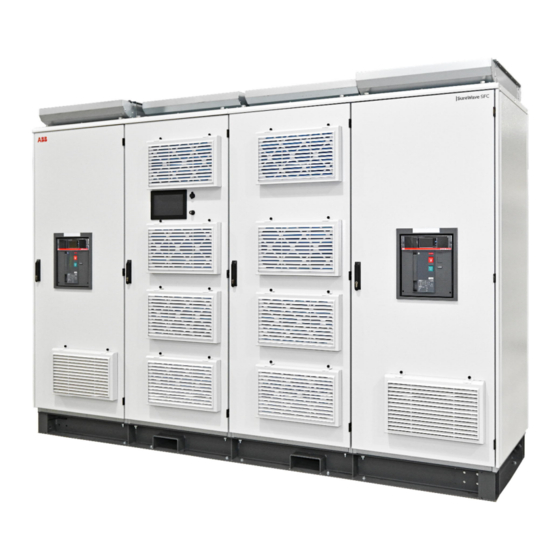
21/78 SUREWAVE SFC USER MANUAL –– Major SFC components This section introduces the main components of the SureWave SFC. Figure 5-5: SureWave product overview Platform Enclosure (PE120-U1) Subcomponents: SureWave Power Electronic Building Blocks (PEBBs) Main controller (MC) Graphic Display Module (GDM) - Page 22 5.4.1.1 SureWave SFC power electronic building blocks The SureWave SFC can contain up to eighteen PEBBs. The Power Electronic Building Blocks are high efficiency three-level bi-directional power electronics IGBT-based converters. Each PEBB is rated at 250 kVA and includes a sine filter. The PEBBs are plug-in modules with au- tomatic smart firmware management and controlled via 2 x fiber optic cables (Tx, Rx) and auxil- iary power provided by a 24 Vdc connection.
- Page 23 5.4.1.2 Graphic display module The GDM is located in the PE120-U1 (main) enclosure. This user interface of the SureWave SFC is connected to the main controller. Through the GDM, it is possible to operate and monitor the SFC, read/edit its parameters, and reset faults.
-
Page 24: Cooling System
24/78 SUREWAVE SFC USER MANUAL Figure 5-9: Termination enclosure –– Cooling system Figure 5-10: Air flow direction... - Page 25 25/78 SUREWAVE SFC USER MANUAL The air enters the SureWave SFC enclosures through the louvre panels at the front and exits through the air outlet at the top. The air intakes, including the louvers and filters, must be maintained and unobstructed when the SureWave SFC is operating.
-
Page 26: Selecting Transformer Configuration
An additional input transformer may be required if voltage matching is required, this must be Delta – Star with a solidly grounded star point to create a TN network supply. This is the best and recommended configuration for the SureWave SFC. TN input... -
Page 27: On-Board Shore Power
27/78 SUREWAVE SFC USER MANUAL TN input 380-480 V 50/60Hz Output Isolation Transformer Delta-Delta SureWave SFC Figure 6-2: Shore to ship typical configuration. –– On-board shore power When the SureWave is installed on board to provide power conversion from the shore supply, a transformer must be provisioned on the input side of the frequency converter. -
Page 28: Specifying Transformer
When specifying a transformer, the engineering application team must be aware and take in to account the required power output of the SureWave SFC. If an input transformer is being used allowance must be made for the converter losses which will be around 4%. If both an input and output transformer is employed, allowance must also be made for the additional losses of the additional transformer. -
Page 29: Model Definition
The product type code defines the characteristics and features of the SureWave SFC. The type code is unique for each model of SureWave SFC and specifies all the parameters needed to order the product. Figure 7-1: SureWave product type code outlines the structure of the type code PCS120 –... -
Page 30: Input Cable Routing & Cb
–– Input cable routing & CB The SureWave SFC is available with provision for top or bottom cable routing for the input termi- nation. Models between 250 kVA and 750 kVA only provides bottom cable routing. Note, termination enclosures are only available for > 750 kVA models. -
Page 31: Output Cable Routing & Cb
–– Output cable routing & CB The SureWave SFC is available with provision for top or bottom cable routing for the output ter- mination. Models between 250 kVA and 750 kVA are only bottom cable routing. Note, termination enclosures are only available for > 750 kVA models. -
Page 32: Input Voltage
480 V Table 7-5: SureWave SFC input voltage type code –– Input frequency The nominal supply input frequency to the SureWave SFC may be set through different sources by an operator with the correct log-in credentials. Input frequency Code 50 Hz... -
Page 33: Output Frequency
60 Hz Table 7-8: SureWave SFC output frequency type code –– Operation The SureWave SFC can be set to operate standalone or to share the load with other power sources e.g., a diesel generator or another SFC. Operation Code Parallel (sharing) -
Page 34: Input Termination Side
–– Input termination side It is possible to order the SureWave SFC with the input termination enclosure on the left or the right side (when viewed from front). This selection is made to best suit the layout of the installa- tion location. -
Page 35: External Lv Psu Feed
In cases where the input side is not RFI grounded (e.g., no output isolation transformer), the supply will have to be externally fed from 3-phase supply clean of common-mode noise, as per LV PSU specifications. External LV PSU feed Code Table 7-12: SureWave SFC external LV PSU feed type code... -
Page 36: Technical Specifications
Input termination cabinet (only > 750 kVA) Left or right Cable entry (only for > 750 kVA) Top or bottom Communication MODBUS TCP/IP, Ethernet Table 8-1: SureWave SFC technical specifications summary –– 250 kVA to 2.25 MVA range specifications 1 PE120 2 PE120 3 PE120... -
Page 37: Dimensional Data
37/78 SUREWAVE SFC USER MANUAL –– Dimensional data 8.2.1 250 kVA to 750 kVA range Dim (W x D x H) 830 x 899 x 2292 mm Weight 1010 kg (fully populated) Floor loading 1353 kg/m² Table 8-3: SureWave 250 kVA to 750 kVA range Refer to 2UCD42000E102_B for more detail 8.2.2 1.0 MVA to 1.5 MVA range... -
Page 38: Circuit Breaker Specifications
Circuit breaker specifications 8.3.1 Input circuit protection The SureWave SFC models < 1 MVA (single enclosure) relies upon upstream protection for cur- rent overload and short circuit protection. Upstream protection should be provided by a circuit breaker between the incoming supply and the SFC as per product specifications, please refer to 2UCD420000E002_a SureWave SFC Technical Data Sheet. - Page 39 SUREWAVE SFC USER MANUAL 8.3.2 Output circuit protection The SureWave SFC models < 1 MVA (single enclosure) relies upon downstream protection for cur- rent overload and short circuit protection when high fault capacities are present on both ends of the SFC. Downstream protection should be provided by a circuit breaker between the incoming supply and the SFC as per product specifications, please refer to 2UCD420000E002_a SureWave SFC Technical Data Sheet.
-
Page 40: Technical Specifications
075xxxxxx) do not have circuit breakers or termination enclosures fitted. It is the responsibility of the customer or system integrator to supply and install these circuit breakers. Power wiring is made directly between these circuit breakers and the SureWave SFC input and output busbars. Figure 9-1: Single enclosure power cables connection 9.1.2 Multiple enclosures (1 MVA to 2.25 MVA) -
Page 41: I/O Interfaces
41/78 SUREWAVE SFC USER MANUAL By default, the input circuit breaker and termination enclosure are located on the left side (front view), and the output circuit breaker and termination enclosure are located on the right side of the plinth. These can be specified as reverse at the time of ordering. - Page 42 42/78 SUREWAVE SFC USER MANUAL Digital inputs Digital outputs Analogue inputs Analogue outputs External voltage sync 9.2.1 Digital inputs A number of digital inputs are provided for customer interface. The inputs are active high, with activation voltage being 24Vdc (supplied). These are summarized in Table 9-1: Summary of con-...
- Page 43 43/78 SUREWAVE SFC USER MANUAL P287-C-2 Stop Stops the system when running, when droop enabled, the system is first unloaded, when standalone the system will (Controlled) ramp down the output voltage prior to stopping. P287-C-3 Reset Rising edge will cause application & PEBB reset.
- Page 44 44/78 SUREWAVE SFC USER MANUAL Terminal no. Name Description P286-A-1 Ready High signal indicates that system is initialized, ready for commands P286-A-2 Running High signal indicates system is in final running state, on load and ramps complete, Signal is low during start-up, shutdown or stopped states...
- Page 45 45/78 SUREWAVE SFC USER MANUAL Terminal no. Name Description Notes P288-V1 (default) Can be configured to control the +/-10V External output voltage setpoint P288-V2 (default) Can be configured to control the +/-10V External output frequency setpoint P288-I1 (default) Can be configured to control the...
- Page 46 46/78 SUREWAVE SFC USER MANUAL Figure 9-8: User DB9 external voltage sensing for sync 9.2.5.1 External voltage sense board The external voltage sense board work without external circuitry and it is rated for 900 Vrms 9.2.6 Ethernet port An ethernet port connection is provided for Modbus TCP and web interfaces can be physically accessed.
- Page 47 SUREWAVE SFC USER MANUAL 9.2.7 Webpage interface A web server of the SureWave SFC is also accessible form the Local Area Network. The webpage interface can be accessed from any device with a web browser by entering the SureWave SFC’s IP address into the address bar of the browser.
-
Page 48: Auxiliary Ac Power Supply For Lv Psu
–– Auxiliary AC power supply for LV PSU The SureWave SFC’s LV PSU can be externally feed if required from a 3-phase, 3-wire AC voltage (380 V to 480 V). The terminal locations are depending on the SFC model. 9.3.1 250 kVA to 750 kVA models For SureWave SFC models between 250 kVA and 750 kVA the 3-phase terminals location is on the peripheral tray, in the bottom right corner of the PE120-U1 enclosure (when view from the front). - Page 49 SUREWAVE SFC USER MANUAL 9.3.2 1 MVA to 2.25 MVA models For SureWave SFC models between 1 MVA and 2.25 MVA the 3-phase terminals location is on the left-hand termination enclosure, next the PE120-U1 (main). Figure 9-12: Terminal connection for external AC feeding (> 750 kVA models)
-
Page 50: User Interface
–– Graphic Display Module (GDM) The primary user interface for configuration of the SureWave SFC is via the Graphic Display Mod- ule (GDM) which is mounted on the door of the PE120-U1 enclosure. The HMI contained in it al- lows local control of the SureWave SFC showing the system status, providing access to the oper- ating parameters, and event history. -
Page 51: Navigation Buttons
Figure 10-2: GDM – SFC stop confirmation screen –– Navigation buttons The navigation buttons provide all different main pages available in the SureWave SFC’s HMI. These provide to the user a friendly and intuitive way to control and monitor the SureWave SFC. - Page 52 52/78 SUREWAVE SFC USER MANUAL Icon Description Main - Dashboard Active Events Event Log Product Information Service Settings User Table 10-1: Navigation buttons 10.2.1 Main Page Refer to Figure 10-3: SureWave – Main page. This shows the dashboard screen, displaying the running state of the SFC.
- Page 53 (direction of power flow is not shown). See Chapter 11 Opera- tion of the SFC for more detail. The power flow in the SureWave SFC system can be summarized into two main states, Running and Stopped. The thick blue lines will indicate the energized sections.
- Page 54 54/78 SUREWAVE SFC USER MANUAL System states Running Table 10-3: SFC power flow running state 10.2.1.4 Column 4- Output. Shows the line-to-line voltage (Vrms) of the outgoing three-phase power supply Output line currents (A) Output frequency (Hz) ...
- Page 55 When clicking on an active event on the left-hand side of the window, a description of the warning or fault is displayed in the events detail field. Figure 10-5: SureWave – Active events page Description of all the icons found in the active events page is shown in Table 10-4: SureWave SFC active events icons...
- Page 56 Indicates the total number of active events Move to the next active events page Return to the previous active events page Return to the first page (latest event) Table 10-4: SureWave SFC active events icons 10.2.2.1 List of warnings Event Description...
- Page 57 / clean if nec- essary. Check ambient air temperature. Check for cooling air recircula- tion. External Neg Se- WARNING: Negative Sequence Check phase rotations of output quence detected on External bus. connections and Vsense meas- urements Table 10-5: SureWave SFC active events icons...
- Page 58 58/78 SUREWAVE SFC USER MANUAL 10.2.2.2 List of faults Event Description Recommended Action EPO Engaged TRIP: Emergency power off Assess the reason for EPO acti- has been activated, 'Hard vation. Release the EPO & reset stop' triggered. SFC. Inhibit Engaged...
- Page 59 Table 10-6: SureWave SFC active events icons 10.2.3 Event Log This page shows a list of the system messages for system events including origin, code, type, timestamp and basic description. The events are classified as information, warnings, or faults.
- Page 60 60/78 SUREWAVE SFC USER MANUAL Icon Description Indicates the number of new unacknowledged events (can be seen from any page) Indicates an fault Indicates a warning Move to the next active events page Return to the previous active events page...
- Page 61 Figure 10-8: Service page 10.2.6 Settings page The Settings page gives access to SureWave SFC system parameters based on the user log-in and their accessibility level. The parameters are organized into different groups, and each one has specific access rights.
- Page 62 62/78 SUREWAVE SFC USER MANUAL 10.2.6.1 List of parameters Parameter Parameter Name Access Dashboard Active Events Event Log Information Service Log Firmware Versions Service Restricted - Login as 'service' required to enable all available func- tions Settings General Customer Name...
- Page 63 63/78 SUREWAVE SFC USER MANUAL 9132 Actual IP Mask 9133 Actual IP Gateway 9134 MAC Address 9135 Ethernet Status 9136 Actual DNS 1 9137 Actual DNS 2 Nominal Settings Input Nominal RMS Voltage Output Nominal RMS Voltage Output Nominal Freq Sel...
- Page 64 Fix P ref Source Fix Q ref Source PEBB Group Configs Input Minimum Capacity Input RFI Mode Input Fan speed Output Minimum Capacity Output RFI Mode Output Fan Speed Input PEBB Bitmap Output PEBB Bitmap Table 10-8: SureWave SFC list of parameters...
- Page 65 It is recommended that the end-user changes the Operator password from the factory default to improve security. Warning: Store the password in a safe place, as ABB cannot reset the password on-site. A lost password will necessitate the returning of the GDM to the factory.
-
Page 66: Operation Of The Sfc
–– Machine state flow diagram While the SureWave SFC system is operational, it has two basic modes of operation Isochronous and droop mode. This section explains the SureWave SFC machine different states transitioning between modes of operation and the logic driving the control of transitioning from one state to another. - Page 67 67/78 SUREWAVE SFC USER MANUAL 11.1.1 System states 11.1.1.1 Stopped Idle - Ready for start command. Inhibited - System inhibit is activated, all start commands are blocked, used for Service. Tripped - System has been tripped, this state is latched, a reset command can attempt to un- latch it, if the fault is not still present.
-
Page 68: System Start
–– System start To start the SureWave SFC the incoming supply needs to be present and the rectifiers AC termi- nals to be energized. Hence, the user has to check the system state e.g., confirming input volt- age is at required levels through the GDM. -
Page 69: Vsi Vs Virtual Generator
This behavior is achieved purely through power electronic control and there are no large spinning masses. When set to virtual generator mode, the SureWave SFC ca be operated in two control modes: 11.3.2.1... -
Page 70: Surewave Sfc Performance
SFC output power can briefly go negative by regenerating power into the source grid. Thus, if the SureWave SFC is used in parallel with one or more energy sources, it can assist in handling load rejection by absorbing any energy transients and dissipating them by regenerat- ing back into the grid. -
Page 71: Remote Ac Bus Synchronization
–– Remote AC bus Synchronization The SureWave SFC can connect to a live AC bus using its in-built synchronizer. This allows unin- terrupted power to an AC bus while transferring from alternate AC power sources such as standby generators to the SFC. - Page 72 SFC, enabling V/F droops on the SureWave SFC might help with stability. 11.6.2.1 SFC to generator installation SLD The installation and connection of the SureWave SFC to allow seamless transfer from the SFC to generator is shown in Figure 11-3: Seamless transfer from the SFC to generator. In this scenario the external voltage sensing must be moved to sense the generator output voltage that is to be brought online.
- Page 73 Once the generator output is stable and ready for loading, enable SureWave V/F droops to allow the SFC to parallel with the generator when the generator is online. Command the SureWave SFC to synchronize to the reference as measured on the exter- nal voltage sense board.
-
Page 74: System Epo
The system Emergency Power Off (EPO) is a digital input linked to the site EPO and use to in- hibit the SureWave SFC operation in case of emergency shut down. For larger systems > 750kVA the emergency inhibit action will not open the CBs located inside the termination enclosures. -
Page 75: Maintenance Schedule
The recommended intervals for maintenance and component replacement are based on the nor- mal operating conditions of the SureWave SFC. The SFC should be checked at least annually by qualified personnel whose recommendations should be followed. Depending on the actual con- ditions of the SureWave SFC, maintenance work can be carried out before or after the recom- mended interval. - Page 76 With regard to purchase orders, the agreed particulars shall prevail. ABB AG does not accept any respon- sibility whatsoever for potential errors or possible lack of information in this docu- ment.
- Page 77 With regard to purchase orders, the agreed particulars shall prevail. ABB AG does not accept any respon- sibility whatsoever for potential errors or possible lack of information in this docu- ment.