Table of Contents

Related Manuals for LG DM5420K


Summary of Contents for LG DM5420K
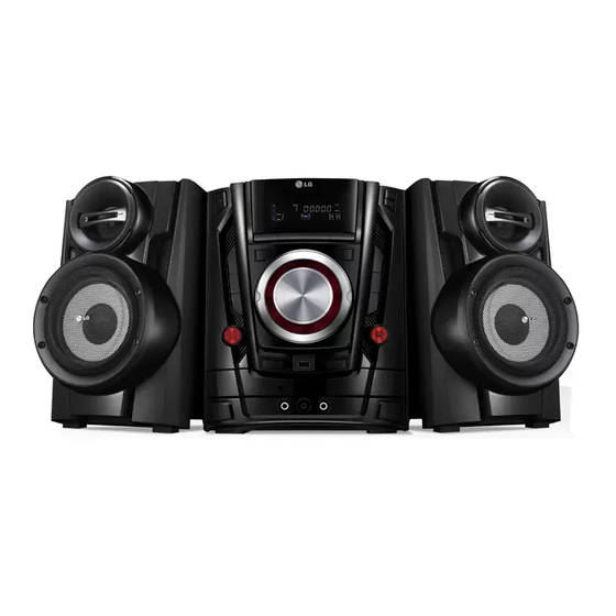
- Page 1 Internal Use Only Website http://biz.lgservice.com KARAOKE DVD Mini Hi-Fi System SERVICE MANUAL MODEL: DM5420K (DM5420K, DMS5420V) CAUTION BEFORE SERVICING THE UNIT, READ THE “SAFETY PRECAUTIONS” IN THIS MANUAL. P/NO : AFN75814472 JULY, 2012...
- Page 2 CONTENTS SECTION 1 ..SUMMARY SECTION 2 ..CABINET & MAIN CHASSIS SECTION 3 ..ELECTRICAL SECTION 4 ..REPLACEMENT PARTS LIST...
-
Page 3: Table Of Contents
SECTION 1 SUMMARY CONTENTS SERVICING PRECAUTIONS ........................1-3 ESD PRECAUTIONS ..........................1-5 SERVICE INFORMATION FOR EEPROM ................... 1-6 PROGRAM UPDATE GUIDE ........................1-7 1. HOW TO UPDATE MICOM PROGRAM 2. HOW TO UPDATE DVD(ESS) PROGRAM SPECIFICATIONS ............................1-9... -
Page 4: Servicing Precautions
SERVICING PRECAUTIONS NOTES REGARDING HANDLING OF THE PICK-UP 1. Notes for transport and storage 1) The pick-up should always be left in its conductive bag until immediately prior to use. 2) The pick-up should never be subjected to external pressure or impact. Storage in conductive bag Drop impact 2. - Page 5 NOTES REGARDING COMPACT DISC PLAYER REPAIRS 1. Preparations 1) Compact disc players incorporate a great many ICs as well as the pick-up (laser diode). These components are sensitive to, and easily affected by, static electricity. If such static electricity is high voltage, components can be damaged, and for that reason components should be handled with care.
-
Page 6: Esd Precautions
ESD PRECAUTIONS Electrostatically Sensitive Devices (ESD) Some semiconductor (solid state) devices can be damaged easily by static electricity. Such components commonly are called Electrostatically Sensitive Devices (ESD). Examples of typical ESD devices are integrated circuits and some field-effect transistors and semiconductor chip components. The following techniques should be used to help reduce the incidence of component damage caused by static electricity. -
Page 7: Service Information For Eeprom
SERVICE INFORMATION FOR EEPROM POWER ON (DVD or USB MODE) TV Display "NO DISC" status Press Set Remote control ‘SETUP -> ▲ -> ▼ -> ◀ -> ▶’ Key -> Select "16:9" DVD Setup -> Display 16:9 mode Press Set Remote control ‘1 ->... -
Page 8: Program Update Guide
PROGRAM UPDATE GUIDE 1. HOW TO UPDATE MICOM PROGRAM (1) Change the fi le name to download as “(MODEL NAME)_(Year)_(Month)_(Date).HEX”. Ex) DM5620_1101190.HEX (2) Copy the fi le to the root folder of USB storage. (3) Put the USB into the set. Change set function to USB function. -
Page 9: How To Update Dvd(Ess) Program
2. HOW TO UPDATE DVD(ESS) PROGRAM (1) Change the fi le name to download as “(MODEL NAME)_(Version)_(Year)_(Month)_(Date).rom”. Ex) LG_DM5620LD1_1101140.rom (2) Copy the fi le to the root folder of USB storage. (3) Put the USB into the set. Change set function to USB function. Then the upgrade process will be started with the upgrade intormation. -
Page 10: Specifications
SPECIFICATIONS • GENERAL Power supply Refer to main label. Power consumption Refer to main label. Net Weight 5.8 kg External dimensions (W x H x D) 272 x 340 x 380 mm Operating conditions Temperature 5 °C to 35 °C (41 °F to 95 °F) Operation status : Horizontal Operating humidity 5 % to 85 %... - Page 11 MEMO 1-10...
- Page 12 SECTION 2 CABINET & MAIN CHASSIS CONTENTS EXPLODED VIEWS ............................. 2-3 1. CABINET AND MAIN FRAME SECTION (DM5420K) ................2-3 2. PACKING ACCESSORY SECTION ......................2-7 3. SPEAKER SECTION ..........................2-8...
- Page 13 MEMO...
-
Page 14: Exploded Views
EXPLODED VIEWS 1. CABINET AND MAIN FRAME SECTION (DM5420K) NOTES) THE EXCLAMATION POINT WITHIN AN EQUILATERAL TRIANGLE IS INTENDED TO ALERT THE SERVICE PERSONNEL TO THE PRESENCE OF IMPORTANT CABLE1 SAFETY INFORMATION IN SERVICE LITERATURE. A41L KEY_L A41R A41A KEY_R... - Page 15 MEMO MEMO...
-
Page 16: Packing Accessory Section
2. PACKING ACCESSORY SECTION 825 FM Wire Antenna 801 Instruction Ass'y 801S Song Book 827 Microphone 832 Blank Disk 808 Battery 900 Remote Control 811 Video Cable 803T Packing 804 Bag 803B Packing 802 Box... -
Page 17: Speaker Section
3. SPEAKER SECTION • FRONT SPEAKER (DMS5420V) A60L A60R... - Page 18 SECTION 3 ELECTRICAL CONTENTS ELECTRICAL TROUBLESHOOTING GUIDE ..................3-2 1. SMPS PART ............................3-2 2. AUDIO ABNORMAL ..........................3-4 3. FUNCTION MODE AUDIO ABNORMAL ....................3-5 4. CD PART ..............................3-7 5. DVD READING CHECK ......................... 3-8 6. USB PART .............................. 3-9 7.
-
Page 19: Electrical Troubleshooting Guide
ELECTRICAL TROUBLESHOOTING GUIDE 1. SMPS PART 16 V F901 nomal? Replace F901 (Use same type fuse). Replace BD901. BD901 nomal? Replace TH901. TH901 nomal? Is VCC (9V-25V) supplied Q904 nomal? to IC901 pin4? Check or replace Q904. Replace D941. D941 nomal? Replace ZD908. - Page 20 ELECTRICAL TROUBLESHOOTING GUIDE F901 nomal? Replace F901 (Use same type fuse). Replace BD901. BD901 nomal? Replace TH901. TH901 nomal? Is VCC (9V-25V) supplied D907 nomal? to IC902 Pin5? Check or replace D907. Replace ZD902. ZD902 nomal? D959 nomal? Replace D959. Replace IC957.
-
Page 21: Audio Abnormal
ELECTRICAL TROUBLESHOOTING GUIDE 2. AUDIO ABNORMAL Audio abnomal Check the signal output Check the speakers connection. of L701, L702, L703, L704. Check the signal output Replace L701, L702, L703, L704. of IC701 pin28, 31, 36, 39. Check the signal input R708, R710, R711, R712 nomal? IC701 pin6, 8,16,18. -
Page 22: Function Mode Audio Abnormal
ELECTRICAL TROUBLESHOOTING GUIDE 3. FUNCTION MODE AUDIO ABNORMAL AUX abnormal Check the signal input of IC112 pin5, 14. Check the signal input circuit (L401,L402,L403,R416,R417,R418,R435,C430, C431). Check the signal input JK101 pin1, 3. Normal. Tuner abnormal Check the signal input of IC112 pin1, 12. Check the signal output Check R400, R401, R402, R403, C402, C403. - Page 23 ELECTRICAL TROUBLESHOOTING GUIDE Tape abnormal Connector check CN105 pin10 VCC(9 V). Does sled motor move? Check the signal input of IC112 pin2, 15. Check power supply circuit (Q2A5). Check the signal output Check R2B1, R2B2 normal? of CN105 pin3, 4. Check Q2A3, Q2A4 circuit.
-
Page 24: Cd Part
ELECTRICAL TROUBLESHOOTING GUIDE 4. CD PART Turn on CD Check connector CN801. Check Open /Close. Check connector CN800. Check “READING” display. Check connector CN800. Check reading OK. Check pick-up movement. Check IC800(S3053), IC100(ES8390). Replace IC800 & IC100. -
Page 25: Dvd Reading Check
ELECTRICAL TROUBLESHOOTING GUIDE 5. DVD READING CHECK Connector locking ckeck CN800, CN801 Does Check CN801 sled motor pin10, 11 (SL-, SL+). Normal move? Check Defective pick-up or IC800 (pin11,12) IC100 pin105 “XOUT” IC100 pin32 “DVD_CLK”, pin106 “XIN” pin33 “DVD_CB”, pin34 “DVD_DO”, signal. -
Page 26: Usb Part
ELECTRICAL TROUBLESHOOTING GUIDE 6. USB PART Turn on USB Check Check connector CN108. “CHECKING” or “USB” display. Check power supply circuit Check IC105 circuit. USB +5 V. Check signal CN108 Check reading OK. pin3, 4 (D+, D-). Check IC100 Normal pin90, 91 (D+, D-). -
Page 27: Vfd Display Check
ELECTRICAL TROUBLESHOOTING GUIDE 7. VFD DISPLAY CHECK Normal VFD display check Check IC300 signal Check IC300 pin1 “VFD- CLK”, pin3 “VFD-DATA”, IC300 normal? pin9, 51 (VCC 5 V). pin4 “VFD-STB”. Replace IC300. Check FB308, L300 normal? Check CN300 pin8. Check CN300 flat film wire. Replace FB308, L300. -
Page 28: Waveforms Of Major Check Point
WAVEFORMS OF MAJOR CHECK POINT 1. WHEN POWER ON, RESET & DATA ETC WAVEFORM RESET(DVD) IC100 PIN72 SPI_CS3(FLASH) IC102 PIN1 SPI_DI IC102 PIN2 SPI_DO IC100 PIN47 2. WHEN USB FUNCTION OPERATING USB PLAYING USB_5V USB_P IC100 PIN90 USB_N IC100 PIN91 3-11... -
Page 29: Starting Action Waveform In Md Device (Sled Home)
3. STARTING ACTION WAVEFORM IN MD DEVICE (SLED HOME) AT POWER ON IC800 PIN4 SLED- IC800 PIN12 SLED+ IC800 PIN11 3-12... -
Page 30: Focus Waveform
4-1. FOCUS WAVEFORM (IN CASE OF CD) INSERT CD IC100 PIN120 IC100 PIN123 IC100 PIN148 IC100 PIN121 4-2. FOCUS WAVEFORM (IN CASE OF CD-RW) INSERT CD-RW IC100 PIN120 IC100 PIN123 IC100 PIN148 IC100 PIN121 3-13... - Page 31 4-3. FOCUS WAVEFORM (IN CASE OF DVD) INSERT DVD IC100 PIN120 IC100 PIN123 IC100 PIN148 IC100 PIN121 4-4. FOCUS WAVEFORM (IN CASE OF DVD-RW) INSERT DVD-RW IC100 PIN120 IC100 PIN123 IC100 PIN148 IC100 PIN121 3-14...
- Page 32 5-1. WHEN DISC READING, SPINDLE KICK SIGNAL (SPNN & SPNP BE USED SPINDLE BREAK DIRECTION) SPNN IC100 PIN131 SPNP IC100 PIN132 IC100 PIN147 IC100 PIN120 5-2. WHEN WE PUSH OPEN OR STOP KEY, SPINDLE BREAK SIGNAL (SPNN & SPNP BE USED SPINDLE BREAK DIRECTION) SPNN IC100 PIN131 SPNP...
-
Page 33: At First Action, Focus Signal A, B, C, D
6. AT FIRST ACTION, FOCUS SIGNAL A, B, C, D CN800 PIN11 CN800 PIN14 CN800 PIN13 CN800 PIN12 7. RF WAVEFORM (ANALOG SCOPE) IC100 PIN136 3-16... -
Page 34: Wiring Diagram
WIRING DIAGRAM MAIN SMPS CN602 CN108 CN101 CN103 CN102 CN601 CN109 CN300 CN301 KEY-L FRONT KEY-R KEY (TOP) 3-17 3-18... -
Page 35: Block Diagram
BLOCK DIAGRAM Y, Pb, Pr Component SDRAM PWM- FLASH PWM AMP Video TAS5342LA MIC AMP S4308 27MHZ A,B,C,D,E,F,RF CD/DVDMDI CDDVDCT,VRCD,VRDVD PWM- PS9831 HP-L/R LDO1,LDO2 HP-OUT MC4580 OPEN/CLOSE MOTOR FOCUS/SLED DRIVE AUX IN SPINDLE/TRACKING ESS8390 (S3053) AMP_STBY AMP- MC4580 WM8738 TURD-N-/N+ TAPE TURD-/+ (S8082) -
Page 36: Circuit Diagrams
MODIFIED OR ALTERED WITHOUT PERMISSION IMPLEMENTATION OF THE LATEST SAFETY AND during Play mode. FROM THE LG CORPORATION. ALL COMPONENTS PERFORMANCE IMPROVEMENT CHANGES INTO SHOULD BE REPLACED ONLY WITH TYPES IDENTICAL THE SET IS NOT DELAYED UNTIL THE NEW SERVICE TO THOSE IN THE ORIGINAL CIRCUIT. -
Page 37: Dvd Mpeg/ Adc/ Composite/ Usb Circuit Diagram
2. DVD MPEG/ ADC/ COMPOSITE/ USB CIRCUIT DIAGRAM R100 C192 220uF/16V X100 FB101 R1B2 FB126 XOUT +3.3VD 470R FB252 +3.3VD 27MHz C100 C102 C142 FB119 C191 FB252 C184 L101 L102 VDD1 VSS4 C127 R137 C128 C126 DB15 UP_SW 270nH 470nH DQ15 UP_SW 100uF/16V... -
Page 38: S3050/ S8082/ Mic Circuit Diagram
3. S3050/ S8082/ MIC CIRCUIT DIAGRAM C808 47uF/16V RFVCC50 R800 C807 RFVCC50 +5VM R803 C800 D800 FB805 KDS-226 FB252 FB806 Q800 C806 C805 FB220 2SK3018 47uF/16V FB807 R802 FB220 100k R801 +3.3VD COREVCC Q807 R829 R830 C8550 R804 R833 C801 D801 R831 R832... -
Page 39: Dsp/ Spbana/ Headphone Circuit Diagram
4. DSP/ SPBANA/ HEADPHONE CIRCUIT DIAGRAM R1H1 C1F1 120R X101 12.288MHz CY10 CY11 CY12 CY13 CY14 CY15 CY16 CY17 CY18 CY19 CY20 CY21 CY22 R1H2 C1F2 +5V_UCOM R1F3 100R R1E5 PWM/DSP_CLK R1F4 R1E6 100R PWM/DSP_DAT C1D6 C1E4 C1D4 C1D5 +5.6V C1D3 R1F6 R1F7... -
Page 40: Amplifier Circuit Diagram
5. AMPLIFIER CIRCUIT DIAGRAM DM-5620 IC701,IC702=TAS5342A PVDD=31.5V DM-5520 IC701=TAS5352A,IC702=NC PVDD=34.5V +36VP DM-5420 IC701=TAS5342LA,IC702=NC PVDD=22V R722 R767 R768 C724 C719 1000uF/50V C725 DM-5320 IC701=TAS5342LA,IC702=NC PVDD=16.5V FB700 +12VA FB220 C700 C704 ZD700 R717 47uF/25V 12V/0.5W C705 R714 C713 C708 GVDD_B GVDD_A C714 L701 R706 9.5uH/7A... -
Page 41: Mcu/ Tuner/ Aux Circuit Diagram
6. MCU/ TUNER/ AUX CIRCUIT DIAGRAM R491 Q402 330R TU_VCC Q401 +5VC TU_VDD 8550 FB401 FB411 8050 R492 TUNER 330R FB80 FB80 +12VA R493 330R TU400 Q117 R494 C401 8550 CN104 CN101 330R C473 R495 330R FAN DC£¨ 6.5 11V£© FB413 VFD_FL+ R4A3... -
Page 42: Vfd/ Key/ Led Circuit Diagram
SW334 R345 R328 SW325 SW318 ST./MONO USER EQ R352 R359 SW331 TUNING+/SKIP/SEARCH TUNING-/SKIP/SEARCH SW335 R346 R329 SW319 SW326 DEMO(TAPE/DEMO) LG EQ R351 R358 TUNER PRESET- SW332 SW336 R347 R330 SW308 SW320 SW327 TIMER R350 R314 R357 SET/CD II SW333 SW337... -
Page 43: Tape Circuit Diagram (Optional Part)
8. TAPE CIRCUIT DIAGRAM (OPTIONAL PART) IC201 IC201 IC202 IC202 R242 R242 P/R_SW-VCC P/R_SW-VCC C243 C243 VCC_SW VCC_SW FB200 FB200 C238 C238 C241 C241 FB203 FB203 FB202 FB202 220R/100MHz 220R/100MHz R209 R209 220R/100MHz 220R/100MHz 4.7uF/50V/NC 4.7uF/50V/NC 220R/100MHz 220R/100MHz PN204 PN204 R217 R217 R202... -
Page 44: Circuit Voltage Chart
CIRCUIT VOLTAGE CHART 1. ICs 2. CAPACITORS Pin No. Specifi cation Input 85 V Input 288 V Location No. Value (uF) Voltage_Spec Positive (+) Negative (-) Location No. Value (uF) Voltage_Spec Positive (+) Negative (-) IC100 ES8390 Input: 288 V / 50 Hz Input: 288 V / 50 Hz 16 38 68 104 155 C119... -
Page 45: Connectors
3. CONNECTORS Location No. Pin No. Voltage Location No. Pin No. Voltage Location No. Pin No. Voltage 1.VFD+ -26V 1.HFM_VCC 4.89V 1.GND 2.VFD- -22V 2.RF_OUT 2.P-12V -11.92V 3.VKK -28.8V 3.LD_VDD 3.P+12V 4.VFD-STB 3.92V 4.MD_DVD 4.GND 5.VFD-DATA 4.06V 5.VR_DVD 5.P+5V 6.VFD-CLK 5.03V 6.GND_PD 6.GND... -
Page 46: Printed Circuit Board Diagrams
PRINTED CIRCUIT BOARD DIAGRAMS 1. SMPS P.C.BOARD 3-41 3-42... -
Page 47: Main P.c.board
2. MAIN P.C.BOARD (TOP VIEW) 3-43 3-44... - Page 48 MAIN P.C.BOARD (BOTTOM VIEW) 3-45 3-46...
-
Page 49: Vfd / Usb P.c.board
3. VFD / USB P.C.BOARD 4. KEY_L P.C.BOARD 5. KEY_R P.C.BOARD 3-47 3-48... -
Page 50: Mic P.c.board
6. MIC P.C.BOARD 7. KEY_TOP P.C.BOARD 3-49 3-50... - Page 51 MEMO MEMO 3-51 3-52...