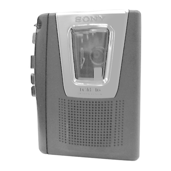
Sony TCM-16 Service Manual
Hide thumbs
Also See for TCM-16:
- Specifications (2 pages) ,
- Operating instructions (2 pages) ,
- Operating instructions manual (2 pages)
Table of Contents
Advertisement
Quick Links
SERVICE MANUAL
Ver 1.0 2000. 12
Model Name Using Similar Mechanism
Tape Transport Mechanism Type
SPECIFICATIONS
Recording system
2-track 1 channel monaural
Frequency range
250 - 6 300 Hz
Speaker
7
Approx. 3.6 cm (1
/
in.) dia.
16
Power output (at 10% harmonic
distortion)
130 mW
Output
Earphone jack (minijack) for 8 -
300Ω earphone
Power requirements
• 3 V DC batteries R6 (AA) × 2
Dimensions (w/h/d) (incl. projecting
parts and controls)
Approx. 112 × 36.6 × 90.3 mm
× 1
× 3
1
1
5
(4
⁄
⁄
⁄
in.)
2
2
8
Mass (not incl. batteries)
Approx. 180 g (6.4 oz.)
Design and specifications are subject
to change without notice.
TCM-16
East European Model
TCM-343
MT-323-118
CASSETTE-CORDER
E Model
Advertisement
Table of Contents

Summary of Contents for Sony TCM-16
- Page 1 TCM-16 SERVICE MANUAL E Model East European Model Ver 1.0 2000. 12 Model Name Using Similar Mechanism TCM-343 Tape Transport Mechanism Type MT-323-118 SPECIFICATIONS Recording system 2-track 1 channel monaural Frequency range 250 - 6 300 Hz Speaker Approx. 3.6 cm (1 in.) dia.
-
Page 2: Table Of Contents
SECTION 1 GENERAL TABLE OF CONTENTS 1. GENERAL ·········································································· 2 This section is extracted from instruction manual. 2. DISASSEMBLY 2-1. Lid Sub Assy, Cassette ···················································· 3 2-2. Main Board, Mechanism Deck ······································· 3 2-3. Belt ·················································································· 4 2-4. “Head, Magnetic”, Pinch Roller ····································· 4 3. -
Page 3: Disassembly
SECTION 2 DISASSEMBLY • The equipment can be removed using the following procedure. Lid Sub Assy, Cassette Main Board, Mechanism Deck Belt “Head, Magnetic”, Pinch Roller Note : Follow the disassembly procedure in the numerical order given. 2-1. LID SUB ASSY, CASSETTE 5 lid sub assy, cassette 4 two cords(SP901) four claws... -
Page 4: Belt
2-3. BELT 2-4. “HEAD, MAGNETIC”, PINCH ROLLER 5 screw (M1.4 × 3.8) 4 screw (1.4) 6 head, magnetic (HRP901) 1 belt (capstan) 3 pinch roller 7 spring (azimuth), compression 2 belt (fr) 8 screw (M1.4) 9 head, magnetic (HE901) 1 lever (pinch roller) INSTALLATION MAIN BOARD On installation MAIN board, adjust to the S101 and the REC lever. -
Page 5: Mechanical Adjustment
SECTION 3 SECTION 4 MECHANICAL ADJUSTMENT ELECTRICAL ADJUSTMENT PRECAUTION PRECAUTION Clean the following parts with a denatured-alcohol-moistened • Supplied voltage : 3.0 V swab : • Switch and control position playback head pinch roller VOL control : mechanical mid capstan rubber belt PAUSE switch : OFF Demagnetize the playback head with a head demagnetizer. -
Page 6: Diagrams
SECTION 5 DIAGRAMS Note on Schematic Diagram: 5-1. IC BLOCK DIAGRAM • All capacitors are in µF unless otherwise noted. pF: µµF 50 WV or IC601 NJM2606AM-TE2 less are not indicated except for electrolytics and tantalums. • All resistors are in Ω and W or less unless otherwise specified. -
Page 7: Block Diagram
TCM-16 5-2. BLOCK DIAGRAM IC101 SP901 PRE/POWER AMP, ALC (SPEAKER) RV101 HRP901 J102 – (PB/REC) HEAD – HE901 – (ERASE) S101 (1/4) S101 (2/4) REC) REC) S101 (3/4) REC) • Signal Path S101 (4/4) REC) : PB MIC901 : REC... -
Page 8: Schematic Diagram
TCM-16 • See page 6 for IC Block Diagram. 5-3. SCHEMATIC DIAGRAM — 9 — — 10 —... -
Page 9: Printed Wiring Board
TCM-16 5-4. PRINTED WIRING BOARD • Semiconductor Location Ref. No. Location D401 F-11 IC101 IC601 — 11 — — 12 —... -
Page 10: Exploded Views
SECTION 6 EXPLODED VIEWS NOTE: • -XX, -X mean standardized parts, so they may • The mechanical parts with no reference number have some differences from the original one. in the exploded views are not supplied. • Items marked “*” are not stocked since they •... -
Page 11: Mechanism Deck Section-1 (Mt-323-118)
6-2. MECHANISM DECK SECTION-1 (MT-323-118) HRP901 M901 HE901 not supplied Ref. No. Part No. Description Remarks Ref. No. Part No. Description Remarks X-3377-250-1 LEVER (2) ASSY, PINCH 3-924-674-01 SPRING (B.T), COMPRESSION 3-925-146-11 BUTTON (FF) 3-924-641-01 GEAR (T REEL) 3-925-147-01 BUTTON (REW) 3-924-726-01 SPRING (M GROUND), TORSION 3-925-148-11 BUTTON (PLAY) 3-907-943-01 BELT (CAPSTAN) -
Page 12: Mechanism Deck Section-2 (Mt-323-118)
6-3. MECHANISM DECK SECTION-2 (MT-323-118) supplied Ref. No. Part No. Description Remarks Ref. No. Part No. Description Remarks 3-321-483-11 RING, RETAINING 3-924-633-01 SPRING (STOP), TENSION 3-701-437-51 WASHER 3-924-622-03 LEVER (STOP) X-3370-384-1 FLYWHEEL ASSY 3-045-541-01 SPRING (PR3), TORSION 3-924-623-04 LEVER (PLAY) 3-924-684-01 SPRING (LOCK PLATE), TENSION 3-924-621-03 LEVER (REW) 3-924-619-06 LEVER (SW) -
Page 13: Electrical Parts List
SECTION 7 MAIN ELECTRICAL PARTS LIST NOTE: • Due to standardization, replacements in the • RESISTORS • SEMICONDUCTORS parts list may be different from the parts All resistors are in ohms. In each case, u: µ, for example: specified in the diagrams or the components METAL: metal-film resistor uA...: µA... - Page 14 MAIN Ref. No. Part No. Description Remarks Ref. No. Part No. Description Remarks R107 1-216-839-11 METAL CHIP 1/16W MISCELLANEOUS R108 1-216-833-11 METAL CHIP 1/16W ************** R109 1-216-833-11 METAL CHIP 1/16W R111 1-216-864-11 SHORT HE901 1-500-232-11 HEAD, MAGNETIC (ERASE) R112 1-216-831-11 METAL CHIP 6.8K 1/16W HRP901 1-500-073-51 HEAD,MAGNETIC(RECORD/PLAYBACK)
- Page 15 TCM-16 Sony Corporation 2000L1619-1 Audio Entertainment Group 9-873-046-31 Printed in Japan ©2000.12 — 18 — Published by General Engineering Dept.


