Table of Contents
Advertisement
Advertisement
Table of Contents

Related Manuals for Asus PRIME X370-A


Summary of Contents for Asus PRIME X370-A
- Page 1 PRIME X370-A...
- Page 2 Product warranty or service will not be extended if: (1) the product is repaired, modified or altered, unless such repair, modification of alteration is authorized in writing by ASUS; or (2) the serial number of the product is defaced or missing.
-
Page 3: Table Of Contents
Contents Safety information ..................iv About this guide ..................iv Package contents ..................vi PRIME X370-A specifications summary ........... vi Chapter 1: Product introduction Before you proceed ..............1-1 Motherboard overview ..............1-1 Central Processing Unit (CPU) ..........1-10 System memory ................. 1-12 Software support ................ -
Page 4: Safety Information
Safety information Electrical safety • To prevent electrical shock hazard, disconnect the power cable from the electrical outlet before relocating the system. • When adding or removing devices to or from the system, ensure that the power cables for the devices are unplugged before the signal cables are connected. If possible, disconnect all power cables from the existing system before you add a device. - Page 5 Refer to the following sources for additional information and for product and software updates. ASUS websites The ASUS website provides updated information on ASUS hardware and software products. Refer to the ASUS contact information. Optional documentation Your product package may include optional documentation, such as warranty flyers, that may have been added by your dealer.
-
Page 6: Package Contents
Dual-channel memory architecture * Hyper DIMM support is subject to the physical characteristics of individual CPUs. ** Refer to www.asus.com for the latest Memory QVL (Qualified Vendors List). Integrated AMD Radeon™ R Series Graphics in the 7th Generation A-series APU Multi-VGA output support: HDMI, DVI-D and D-Sub ports - Supports HDMI 1.4b with maximum resolution of 4096 x 2160 @24Hz / 2560 x... - Page 7 Dependable Stability ASUS 5X PROTECTION III - ASUS SafeSlot Core: Fortified PCIe Slot prevents damage - ASUS LANGuard: Protects against LAN surges, lightning strikes and static- electricity discharges! - ASUS Overvoltage Protection: World-class circuit-protecting power design - ASUS Stainless-Steel Back I/O: 3X corrosion-resistance for greater durability!
- Page 8 1 x System panel connector 128 Mb Flash ROM, UEFI AMI BIOS, PnP, WfM2.0, SM BIOS 3.0, ACPI 6.1, Multi-language BIOS, ASUS EZ Flash 3, ASUS CrashFree BIOS 3, My BIOS features Favorites, Last Modified log, F12 PrintScreen, ASUS DRAM SPD (Serial...
-
Page 9: Before You Proceed
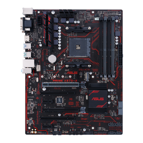
2260 2242 PRIME X370-A Realtek ® 8111H PCIEX16_1 PCI1 ® X370 1083 PCIEX1_1 Super PCIEX16_2 PCI2 PCIEX1_2 SATA6G_4 SATA6G_3 SATA6G_2 SATA6G_1 USB3_12 USB56 USB34 AAFP CLRTC PANEL Unplug the power cord before installing or removing the motherboard. Failure to do so can cause you physical injury and damage motherboard components. ASUS PRIME X370-A... - Page 10 +3 Volts -12 Volts +3 Volts +3 Volts requirement for your system, refer to the Recommended PIN 1 Power Supply Wattage Calculator at http://support.asus.com/ PowerSupplyCalculator/PSCalculator.aspx?SLanguage=en-us for details. CPU and chassis fan connectors (4-pin CPU_FAN, 4-pin CHA_FAN1/2) Connect the fan cables to the fan connectors on the motherboard, ensuring that the black wire of each cable matches the ground pin of the connector. Chapter 1: Product introduction...
- Page 11 PIN 1 The FAN RGB header supports CPU fans LED cable with multi-color LED strips (12V/G/R/B) and with a maximum power rating of 1A (12V). Before you install or remove any component, ensure that the ATX power supply is switched off or the power cord is detached from the power supply. Failure to do so may cause severe damage to the motherboard, peripherals, or components. M.2 socket 3 M.2(SOCKET3) These sockets allow you to install M.2 (NGFF) SSD modules. • This socket supports M Key and 2242 / 2260 / 2280 / 22110 storage devices. • Due to CPU limitation, M.2 socket supported varies by processor. Refer to the specifications summary table for more details. AMD AM4 CPU socket This motherboard comes with an AMD AM4 socket designed for AMD Ryzen™ / 7th Generation A-series / Athlon™ processors. For more details, refer to Central Processing Unit (CPU). ASUS PRIME X370-A...
- Page 12 DDR4 DIMM slots Install 2 GB, 4 GB, 8 GB, and 16 GB unbuffered ECC and non-ECC DDR4 DIMMs into these DIMM sockets. For more details, refer to System memory. AMD X370 SATA 6.0Gb/s ports (7-pin SATA6G_1~6) SATA6G These ports connect to SATA 6.0 Gb/s hard disk drives via SATA 6.0 Gb/s signal cables. RSATA_TXP RSATA_TXN RSATA_RXN RSATA_RXP System panel connector (20-5 pin PANEL) PANEL This connector supports several chassis-mounted functions. +PWR_LED- PWR_SW SPEAKER • System power LED (4-pin PWR_LED) This 4-pin connector is for the system power LED. Connect the chassis power LED cable to this connector. The system power LED lights up when you turn on the system power, PIN 1 and blinks when the system is in sleep mode. •...
- Page 13 Front panel audio connector (10-1 pin AAFP) This connector is for a chassis-mounted front panel audio I/O module that supports either HD Audio or legacy AC`97 audio standard. Connect one end of the front panel audio I/O module cable to this connector. AAFP PIN 1 HD-audio-compliant Legacy AC’97 pin definition compliant definition • We recommend that you connect a high-definition front panel audio module to this connector to avail of the motherboard’s high-definition audio capability. • If you want to connect a high-definition front panel audio module to this connector, set the Front Panel Type item in the BIOS setup to [HD]. If you want to connect an AC’97 front panel audio module to this connector, set the item to [AC97]. By default, this connector is set to [HD]. ASUS PRIME X370-A...
- Page 14 Clear RTC RAM (2-pin CLRTC) This header allows you to clear the Real Time Clock (RTC) RAM in CMOS. You can clear the CMOS memory of date, and system setup parameters by erasing the CMOS RTC RAM data. The onboard button cell battery powers the RAM data in CMOS, which include system setup information such as system passwords. To erase the RTC RAM: Turn OFF the computer and unplug the power cord. CLRTC Use a metal object such as a screwdriver to short the two pins. Plug the power cord and turn ON the computer. Hold down the <Del> key during the boot process and enter BIOS setup to re-enter data. PIN 1 If the steps above do not help, remove the onboard battery and short the two pins again to clear the CMOS RTC RAM data. After clearing the CMOS, reinstall the battery. PCI Express 2.0 x1 slots This motherboard has two PCI Express 2.0 x1 slots that support PCI Express x1 network cards, SCSI cards, and other cards that comply with the PCI Express specifications.
- Page 15 – – – – – – XHCI controller SATA controller – shared – – – – – – HD audio controller – – – shared – – – – Realtek LAN controller – – shared – – – – – When using PCI cards on shared slots, ensure that the drivers support “Share IRQ” or that the cards do not need IRQ assignments. Otherwise, conflicts will arise between the two PCI groups, making the system unstable and the card inoperable. ASUS PRIME X370-A...
- Page 16 1.2.2 Rear panel connectors PS/2 keyboard/mouse combo port. This port is for a PS/2 mouse or keyboard. Video Graphics Adapter (VGA) port. This 15-pin port is for a VGA monitor or other VGA-compatible devices. USB 3.1 Gen 1 ports. These two 9-pin Universal Serial Bus (USB) ports connect to USB 3.1 Gen 1 devices. • USB 3.1 Gen 1 devices can only be used for data storage. • Due to the design of AMD AM4 series chipset, all USB devices connected to the USB 2.0 and USB 3.1 Gen 1 ports are controlled by the xHCI controller. USB 3.1 Gen 2 ports (teal blue, Type A). These 9-pin Universal Serial Bus 3.1 (USB 3.1 Gen 2) ports are for USB 3.1 Gen 2 devices. LAN (RJ-45) port. This port allows Gigabit connection to a Local Area Network (LAN) through a network hub. Refer to the table below for the LAN port LED indications. LAN port LED indications Speed Activity Link Activity/Link LED...
- Page 17 Audio 2.1, 4.1, 5.1, or 7.1-channel configuration Headset Port 4.1-channel 5.1-channel 7.1-channel 2.1-channel Light Blue (Rear panel) Line In Rear Speaker Out Rear Speaker Out Rear Speaker Out Lime (Rear panel) Line Out Front Speaker Out Front Speaker Out Front Speaker Out Pink (Rear panel) Mic In Mic In Bass / Center Bass / Center Lime (Front panel) Side Speaker Out HDMI port. This port is for a High-Definition Multimedia Interface (HDMI) connector, and is HDCP compliant allowing playback of HD DVD, Blu-Ray, and other protected content. DVI-D port. This port is for any DVI-D compatible device. DVI-D can not be converted to output from RGB Signal to CRT and is not compatible with DVI-I. USB 2.0 ports. These 4-pin Universal Serial Bus (USB) ports are for USB 2.0/1.1 devices. ASUS PRIME X370-A...
-
Page 18: Central Processing Unit (Cpu)
Central Processing Unit (CPU) The motherboard comes with an AMD AM4 socket designed for AMD Ryzen™ / 7th Generation A-series / Athlon™ processors. Unplug all power cables before installing the CPU. The AM4 socket has a different pinout from the FM2+ / FM2 socket. Ensure that you use a CPU designed for the AM4 socket. The CPU fits in only one correct orientation. DO NOT force the CPU into the socket to prevent bending the pins and damaging the CPU! Installing the CPU Apply the Thermal Interface Material to the CPU heatsink and CPU before you install the heatsink and fan if necessary. 1-10 Chapter 1: Product introduction... - Page 19 Installing the CPU heatsink and fan assembly Type 1 Type 2 Remove the screws and the retention module only. Do not remove the plate on the bottom. ASUS PRIME X370-A 1-11...
-
Page 20: System Memory
Overview This motherboard comes with four Double Data Rate 4 (DDR4) Dual Inline Memory Module (DIMM) sockets. The figure illustrates the location of the DDR4 DIMM sockets: Channel Sockets DIMM_A1 DIMM_A2 Channel A DIMM_A1 & DIMM_A2 DIMM_B1 Channel B DIMM_B1 & DIMM_B2 DIMM_B2 • You may install varying memory sizes in Channel A and Channel B. The system maps the total size of the lower-sized channel for the dual-channel configuration. Any excess memory from the higher-sized channel is then mapped for single-channel operation. • Always install DIMMs with the same CAS latency. For optimal compatibility, we recommend that you install memory modules of the same version or date code (D/C) from the same vendor. Check with the retailer to get the correct memory modules. • For system stability, use a more efficient memory cooling system to support a full memory load (4 DIMMs). • Refer to www.asus.com for the latest Memory QVL (Qualified Vendors List) Recommended memory configurations Installing a DIMM To remove a DIMM 1-12 Chapter 1: Product introduction... -
Page 21: Software Support
To run the Support DVD Place the Support DVD into the optical drive. If Autorun is enabled in your computer, the DVD automatically displays the lists of the unique features of your ASUS motherboard. Click the Driver, Utilities, Manual, or Special tabs to display their respective menus. The following screen is for reference only. Click to install Select an item/ subitem that you Click a tab to want to install display Support DVD information If Autorun is NOT enabled in your computer, browse the contents of the Support DVD to locate the file Setup.exe in the root folder. Double-click the Setup.exe to run the DVD. ASUS PRIME X370-A 1-13... -
Page 22: Chapter 2: Bios Information
Managing and updating your BIOS Save a copy of the original motherboard BIOS file to a USB flash disk in case you need to restore the BIOS in the future. Copy the original motherboard BIOS using the ASUS Update utility. - Page 23 2.1.2 ASUS EZ Flash 3 The ASUS EZ Flash 3 feature allows you to update the BIOS without using an OS‑based utility. • Ensure that you load the BIOS default settings to ensure system compatibility and stability. Select the Load Optimized Defaults item under the Exit menu.
- Page 24 2.1.3 ASUS CrashFree BIOS 3 utility The ASUS CrashFree BIOS 3 is an auto recovery tool that allows you to restore the BIOS file when it fails or gets corrupted during the updating process. You can restore a corrupted BIOS file using the motherboard support DVD or a USB flash drive that contains the updated BIOS file.
- Page 25 On the BIOS Updater screen, press <Tab> to switch from Files panel to Drives panel then select D:. ASUSTeK BIOS Updater for DOS V1.31 [2014/08/01] Current ROM Update ROM BOARD: PRIME X370-A BOARD: Unknown VER: 0302 (H :00 B :00)
-
Page 26: Bios Setup Program
The BIOS setup screens shown in this section are for reference purposes only, and may not exactly match what you see on your screen. Visit the ASUS website at www.asus.com to download the latest BIOS file for this • motherboard. - Page 27 2.2.1 EZ Mode By default, the EZ Mode screen appears when you enter the BIOS setup program. The EZ Mode provides you an overview of the basic system information, and allows you to select the display language, system performance mode, fan profile and boot device priority. To access the Advanced Mode, click Advanced Mode(F7) or press <F7>.
- Page 28 MyFavorite Hot Keys Language Menu bar Searches Scroll bar Sub-menu item Configuration fields General help Menu items Goes back to EZ Mode Pop-up window Last modified Displays the CPU settings temperature, CPU and memory voltage output 2‑7 ASUS PRIME X370-A...
- Page 29 Menu bar The menu bar on top of the screen has the following main items: My Favorites For saving the frequently‑used system settings and configuration Main For changing the basic system configuration Ai Tweaker For changing the overclocking settings Advanced For changing the advanced system settings For displaying the system temperature, power status, and changing the Monitor...
- Page 30 Search on FAQ Move your mouse over this button to show a QR code. Scan this QR code with your mobile device to connect to the ASUS BIOS FAQ web page. You can also scan the QR code below. ASUS PRIME X370-A...
- Page 31 2.2.3 QFan Control The QFan Control allows you to set a fan profile or manually configure the operating speed of your CPU and chassis fans. Click to select a fan to be configured Select a profile to apply to Click to apply the your fans fan setting Click to undo the...
- Page 32 Select the fan that you want to configure and to view its current status. Click and drag the speed points to adjust the fans’ operating speed. Click Apply to save the changes then click Exit (ESC). 2-11 ASUS PRIME X370-A...
-
Page 33: My Favorites
My Favorites MyFavorites is your personal space where you can easily save and access your favorite BIOS items. Adding items to My Favorites To add BIOS items: Press <F3> on your keyboard or click from the BIOS screen to open Setup Tree Map screen. -
Page 34: Main Menu
RAM to clear the BIOS password. See section 1.2 Motherboard overview for information on how to erase the RTC RAM. • The Administrator or User Password items on top of the screen show the default Not Installed. After you set a password, these items show Installed. 2‑13 ASUS PRIME X370-A... - Page 35 Administrator Password If you have set an administrator password, we recommend that you enter the administrator password for accessing the system. To set an administrator password: Select the Administrator Password item and press <Enter>. From the Create New Password box, key in a password, then press <Enter>. Confirm the password when prompted.
-
Page 36: Ai Tweaker Menu
The values range from 90.0MHz to 300.0MHz. We recommend you to set the value based on the CPU specification, as high APU frequencies may damage the CPU permanently. This item appears only when you install an AMD 7 Generation A‑series/Athlon processor. 2‑15 ASUS PRIME X370-A... - Page 37 2.5.2 Memory Frequency [Auto] The configuration options displayed vary depending on the CPU installed. Allows you to set the memory operating frequency. Configuration options: [Auto] [DDR4‑ 1346MHz] [DDR4‑1616MHz] [DDR4‑1885MHz] [DDR4‑2154MHz] [DDR4‑2424MHz] Selecting a very high memory frequency may cause the system to become unstable! If this happens, revert to the default setting.
- Page 38 The boosted performance may vary depending on the CPU specification. Do not remove the thermal module. • The configuration levels vary depending on the CPUs installed. VDDCR SOC Load Line Calibration [Auto] Allows you to select the CPU/NB Load‑Line Calibration mode. Configuration options: [Auto] [Regular] [High] [Extreme] 2‑17 ASUS PRIME X370-A...
- Page 39 Reducing phase number under light system loading to increase VRM efficiency. [Optimized] Loads the ASUS optimized phase tuning profile. [Extreme] Proceeds the full phase mode. DO NOT remove the thermal module when switching to Extreme. The thermal conditions should be monitored.
- Page 40 Allows you to set the VTTDDR voltage. Use the <+> and <‑> keys to adjust the value. 2.5.18 VPP_MEM Voltage [Auto] Allows you to set the VPP_MEM voltage. Use the <+> and <‑> keys to adjust the value. 2-19 ASUS PRIME X370-A...
-
Page 41: Advanced Menu
Advanced menu The Advanced menu items allow you to change the settings for the CPU and other system devices. Be cautious when changing the settings of the Advanced menu items. Incorrect field values can cause the system to malfunction. AMD fTPM switch [Disabled] Enables or disables AMD CPU firmware TPM. - Page 42 SATA Port items show Not Present if no SATA device is installed to the corresponding SATA port. Hyper Kit Mode [Disabled] Disable this option for M.2 devices. Enable this option for ASUS Hyper Kit card. Configuration options: [Disabled] [Enabled] 2-21...
- Page 43 SATA Port Enable [Enabled] Enables or disables the SATA ports. Configuration options: [Disabled] [Enabled] SATA Mode [AHCI] Allows you to set the SATA configuration. [RAID] Set to [RAID] when you want to create a RAID configuration from the SATA hard disk drives. [AHCI] Set to [AHCI] when you want the SATA hard disk drives to use the AHCI (Advanced Host Controller Interface).
- Page 44 This item allows you to enable or disable the RTC (Real‑Time Clock) to generate a wake event and configure the RTC alarm date. When enabled, you can set the days, hours, minutes, or seconds to schedule an RTC alarm date. Configuration options: [Disabled] [Enabled] 2‑23 ASUS PRIME X370-A...
- Page 45 2.6.6 Network Stack Configuration Network Stack [Disabled] This item allows user to disable or enable the UEFI network stack. Configuration options: [Disabled] [Enabled] The following two items appear only when you set the previous item to [Enabled]. Ipv4 / Ipv6 PXE Support [Enabled] This item allows you to enable or disable the Ipv4/Ipv6 PXE wake event.
-
Page 46: Monitor Menu
N/A. Select [Ignore] if you do not wish to display the detected speed. 2.7.3 VDDCR CPU Voltage, 3.3V Voltage, 5V Voltage, 12V Voltage The onboard hardware monitor automatically detects the voltage output through the onboard voltage regulators. Select [Ignore] if you do not want to detect this item. 2‑25 ASUS PRIME X370-A... - Page 47 2.7.4 Q-Fan Configuration The subitems in this menu allows you to configure the Q‑Fan features. Q-Fan Tuning Click [OK] button to detect the lowest speed and configure the minimum duty circle for each fan. Do not shut down or reset your system during the tuning progress. Configuration options: [Ok] [Cancel] CPU Q-Fan Control [PWM Mode] [Disabled]...
- Page 48 Use the <+> or <‑> keys to set the value for Chassis Fan Middle Temperature. Chassis Fan 1/2 Middle Duty Cycle(%) [60] Use the <+> or <‑> keys to adjust the chassis fan middle duty cycle. The values range from 60% to 100%. 2‑27 ASUS PRIME X370-A...
-
Page 49: Boot Menu
Chassis Fan 1/2 Lower Temperature [40] Use the <+> or <‑> keys to adjust the chassis fans’ lower temperature. The values range from 0°C to 75°C. Chassis Fan 1/2 Min. Duty Cycle(%) [60] Use the <+> or <‑> keys to adjust the minimum chassis fan duty cycle. The values range from 60% to 100%. - Page 50 This item allows you to go to EZ Mode of the BIOS after POST. 2.8.3 CSM (Compatibility Support Module) Allows you to configure the CSM (Compatibility Support Module) items to fully support the various VGA, bootable devices and add‑on devices for better compatibility. 2-29 ASUS PRIME X370-A...
- Page 51 Launch CSM [Enabled] [Auto] The system automatically detects the bootable devices and the add‑on devices. [Enabled] For better compatibility, enable the CSM to fully support the non‑UEFI driver add‑on devices or the Windows UEFI mode. ® [Disabled] Disable the CSM to fully support the Windows Security Update and ®...
- Page 52 Allows you to load the additional KEK from a storage device for an additional db and dbx loaded management. The db file must be formatted as a UEFI variable structure with time‑based authenticated variable. DBX Management 2‑31 ASUS PRIME X370-A...
- Page 53 These items specify the boot device priority sequence from the available devices. The number of device items that appears on the screen depends on the number of devices installed in the system. To select the boot device during system startup, press <F8> when ASUS Logo appears. 2.8.6 Boot Override These items displays the available devices.
-
Page 54: Tool Menu
<Enter> to display the submenu. 2.9.1 ASUS EZ Flash 3 Utility Allows you to run ASUS EZ Flash 3. Press [Enter] to launch the ASUS EZ Flash 3 screen. For more details, see section 2.1.2 ASUS EZ Flash 3. 2.9.2 Setup Animator [Disabled] Enables or disables the Setup animator. -
Page 55: Exit Menu
2.9.4 ASUS SPD Information DIMM Slot number [DIMM_A1] Displays the Serial Presence Detect (SPD) information of the DIMM module installed on the selected slot. Configuration options: [DIMM_A1] [DIMM_B1] [DIMM_A2] [DIMM_B2] 2.10 Exit menu The Exit menu items allow you to load the optimal default values for the BIOS items, and save or discard your changes to the BIOS items. -
Page 56: Appendix
Son utilisation est sujette aux deux conditions suivantes : (1) cet appareil ne doit pas créer d’interférences et (2) cet appareil doit tolérer tout type d’interférences, y compris celles susceptibles de provoquer un fonctionnement non souhaité de l’appareil. ASUS PRIME X370-A... - Page 57 ASUS Recycling/Takeback Services ASUS recycling and takeback programs come from our commitment to the highest standards for protecting our environment. We believe in providing solutions for you to be able to responsibly recycle our products, batteries, other components as well as the packaging materials.
- Page 58 Slovensky Spoločnosť ASUSTeK Computer Inc. týmto vyhlasuje, že toto Cijeli tekst EU izjave o sukladnosti dostupan je na: www.asus.com/support zariadenie vyhovuje základným požiadavkám a ostatým príslušným ustanoveniam príslušných smerníc. Celý text vyhlásenia o zhode pre štáty EÚ...
-
Page 59: Asus Contact Information
+1-510-739-3777 +1-510-608-4555 Web site http://www.asus.com/us/ Technical Support Support fax +1-812-284-0883 Telephone +1-812-282-2787 Online support http://qr.asus.com/techserv ASUS COMPUTER GmbH (Germany and Austria) Address Harkort Str. 21-23, 40880 Ratingen, Germany +49-2102-959931 Web site http://www.asus.com/de Online contact http://eu-rma.asus.com/sales Technical Support Telephone +49-2102-5789555 Support Fax... - Page 60 800 Corporate Way, Fremont Phone/Fax No: (510)739-3777/(510)608-4555 hereby declares that the product Product Name : Motherboard Model Number : PRIME X370-A Conforms to the following specifications: FCC Part 15, Subpart B, Unintentional Radiators Supplementary Information: This device complies with part 15 of the FCC Rules. Operation is subject to the...