Table of Contents
Advertisement
Advertisement
Table of Contents

Related Manuals for Asus PRIME A320M-R


Summary of Contents for Asus PRIME A320M-R
- Page 1 PRIME A320M-R...
- Page 2 Product warranty or service will not be extended if: (1) the product is repaired, modified or altered, unless such repair, modification of alteration is authorized in writing by ASUS; or (2) the serial number of the product is defaced or missing.
-
Page 3: Table Of Contents
Contents Safety information ..................iv About this guide ..................iv Package contents ..................vi PRIME A320M-R specifications summary ..........vi Chapter 1 Product introduction Motherboard overview ................1-1 Central Processing Unit (CPU) ..............1-7 System memory ..................1-8 Chapter 2 BIOS information BIOS setup program ................. -
Page 4: Safety Information
Safety information Electrical safety • To prevent electrical shock hazard, disconnect the power cable from the electrical outlet before relocating the system. • When adding or removing devices to or from the system, ensure that the power cables for the devices are unplugged before the signal cables are connected. If possible, disconnect all power cables from the existing system before you add a device. - Page 5 Refer to the following sources for additional information and for product and software updates. ASUS websites The ASUS website provides updated information on ASUS hardware and software products. Refer to the ASUS contact information. Optional documentation Your product package may include optional documentation, such as warranty flyers, that may have been added by your dealer.
-
Page 6: Package Contents
PRIME A320M-R specifications summary AM4 socket for AMD Ryzen™ / 7th Generation A-series / Athlon™ processors Supports CPU up to 4 cores* * For limited CPU only, refer to www.asus.com for the AMD® CPU support list. AMD A320 chipset Chipset AMD Ryzen™ processors:... - Page 7 - ASUS Overvoltage Protection - World-class circuit-protecting power design - ASUS DIGI+ VRM - 3 Phase digital power design - ASUS DRAM Overcurrent Protection - Prevents damage from short circuits - ASUS Stainless-Steel Back I/O - 3X corrosion-resistance for greater durability...
- Page 8 128 Mb Flash ROM, UEFI AMI BIOS, PnP, DMI2.0, WfM2.0, SM BIOS 3.0, ACPI 6.0, Multi-language BIOS, ASUS EZ Flash 3, ASUS CrashFree BIOS BIOS features 3, F3 My Favorites, Last Modified log, F12 PrintScreen, ASUS DRAM SPD (Serial Presence Detect) memory information, F6 Qfan Control, ErP Ready Manageability WfM 2.0, DMI 2.0, WOL by PME, PXE...
-
Page 9: Chapter 1 Product Introduction
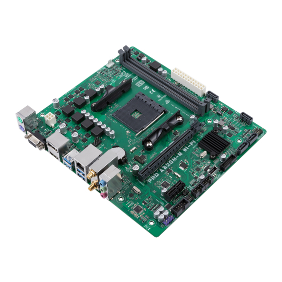
CPU_FAN DIGI +VRM ATX12V Place this side towards HDMI the rear of the chassis U31G1_56 CHA_FAN U31G1_34 LAN_USB12 128Mb BIOS AUDIO PCIEX16 Realtek 8111H Super ® A320 PCIEX1_1 SPEAKER AAFP USB34 USB56 SATA6G_4 U31G1_12 CLRTC F_PANEL Scan the QR code to get the detailed pin definitions. ASUS PRIME A320M-R... - Page 10 • DO NOT forget to connect the 4-pin ATX +12V power plug. Otherwise, the system will not boot up. • We recommend that you use a PSU with higher power output when configuring a system with more power-consuming devices or when you intend to install additional devices. The system may become unstable or may not boot up if the power is inadequate. • If you are uncertain about the minimum power supply requirement for your system, refer to the Recommended Power Supply Wattage Calculator at http://support. asus.com.cn/PowerSupply.aspx?SLanguage=en for details. CPU and chassis fan connectors (4-pin CPU_FAN, 4-pin CHA_FAN) Connect the fan cables to the fan connectors on the motherboard, ensuring that the black wire of each cable matches the ground pin of the connector. Do not forget to connect the fan cables to the fan connectors. Insufficient air flow inside the system may damage the motherboard components. These are not jumpers! Do not place jumper caps on the fan connectors! The CPU_FAN connector supports a CPU fan of maximum 1A (12 W) fan power. AMD AM4 CPU socket This motherboard comes with an AMD AM4 socket designed for AMD Ryzen™/7th Generation A-series/Athlon™ Processors. For more details, refer to Central Processing Unit (CPU). DDR4 DIMM slots Install 2 GB, 4 GB, 8 GB, and 16 GB unbuffered ECC and non-ECC DDR4 DIMMs into these DIMM sockets.
- Page 11 3.1 Gen 1 front or rear panel ports. With an installed USB 3.1 Gen 1 module, you can enjoy all the benefits of USB 3.1 Gen 1 including faster data transfer speeds of up to 5Gbps, faster charging time for USB-chargeable devices, optimized power efficiency and backward compatibility with USB 2.0. USB 2.0 connectors (10-1 pin USB34, USB56) These connectors are for USB 2.0 ports. Connect the USB module cable to any of these connectors, then install the module to a slot opening at the back of the system chassis. These USB connectors comply with USB 2.0 specifications and support up to 480Mbps connection speed. Never connect a 1394 cable to the USB connectors. Doing so will damage the motherboard! Front panel audio connector (10-1 pin AAFP) This connector is for a chassis-mounted front panel audio I/O module that supports either HD Audio or legacy AC`97 audio standard. Connect one end of the front panel audio I/O module cable to this connector. • We recommend that you connect a high-definition front panel audio module to this connector to avail of the motherboard’s high-definition audio capability. • If you want to connect a high-definition front panel audio module to this connector, set the Front Panel Type item in the BIOS setup to [HD Audio]. If you want to connect an AC’97 front panel audio module to this connector, set the item to [AC97]. By default, this connector is set to [HD Audio]. ASUS PRIME A320M-R...
- Page 12 PCI Express 2.0 x1 slot This motherboard has one PCI Express 2.0 x1 slot that supports PCI Express x1 network cards, SCSI cards, and other cards that comply with the PCI Express specifications. Serial port connector (10-1 pin COM) This connector is for a serial (COM) port. Connect the serial port module cable to this connector, then install the module to a slot opening at the back of the system chassis. PCI Express 3.0 / 2.0 x16 slot This motherboard supports one PCI Express 3.0 / 2.0 x16 graphic card that complies with the PCI Express specifications. Chapter 1: Product introduction...
- Page 13 Speed LED Activity/Link LED Description Status Description Status No link 10Mbps connection Orange Linked ORANGE 100Mbps connection Orange Data activity GREEN 1Gbps connection (Blinking) LAN port Orange (Blinking Ready to wake then steady) up from S5 mode Line In port (light blue). This port connects to the tape, CD, DVD player, or other audio sources. Line Out port (lime). This port connects to a headphone or a speaker. In the 4.1, 5.1and 7.1-channel configurations, the function of this port becomes Front Speaker Out. ASUS PRIME A320M-R...
- Page 14 Microphone port (pink). This port connects to a microphone. Refer to the audio configuration table for the function of the audio ports in 2.1, 4.1, 5.1, or 7.1-channel configuration. Audio 2.1, 4.1, 5.1 or 7.1-channel configuration Headset Port 4.1-channel 5.1-channel 7.1-channel 2.1-channel Light Blue (Rear panel) Line In Rear Speaker Out Rear Speaker Out Rear Speaker Out Lime (Rear panel) Line Out Front Speaker Out Front Speaker Out Front Speaker Out Pink (Rear panel) Mic In Mic In Bass/Center Bass/Center Lime (Front panel) Side Speaker Out USB 2.0 ports. These 4-pin Universal Serial Bus (USB) ports are for USB 2.0/1.1 devices. HDMI port. This port is for a High-Definition Multimedia Interface (HDMI) connector, and is HDCP compliant allowing playback of HD DVD, Blu-ray, and other protected content.
-
Page 15: Central Processing Unit (Cpu)
Central Processing Unit (CPU) The motherboard comes with an AMD AM4 socket designed for AMD Ryzen™/ 7 Generation A-series/ Athlon™ processors. Unplug all power cables before installing the CPU. The AM4 socket has a different pinout from the FM2+/FM2 socket. Ensure that you use a CPU designed for the AM4 socket. The CPU fits in only one correct orientation. DO NOT force the CPU into the socket to prevent bending the pins and damaging the CPU! Installing the CPU Apply the Thermal Interface Material to the CPU heatsink and CPU before you install the heatsink and fan if necessary. ASUS PRIME A320M-R... -
Page 16: System Memory
System memory Overview This motherboard comes with two Double Data Rate 4 (DDR4) Dual Inline Memory Module (DIMM) sockets. The figure illustrates the location of the DDR4 DIMM sockets: Channel Sockets DIMM_B1 Channel A DIMM_A1 DIMM_A1 Channel B DIMM_B1 • You may install varying memory sizes in Channel A and Channel B. The system maps the total size of the lower-sized channel for the dual-channel configuration. Any excess memory from the higher-sized channel is then mapped for single-channel operation. • Always install DIMMs with the same CAS latency. For optimal compatibility, we recommend that you install memory modules of the same version or date code (D/C) from the same vendor. Check with the retailer to get the correct memory modules. • For system stability, use a more efficient memory cooling system to support a full memory load (2 DIMMs). • Refer to www.asus.com for the latest Memory QVL (Qualified Vendors List) Recommended memory configuration Installing a DIMM To remove a DIMM Chapter 1: Product introduction... -
Page 17: Chapter 2 Bios Information
Entering BIOS Setup after POST To enter BIOS Setup after POST: Press <Ctrl>+<Alt>+<Del> simultaneously. Press the reset button on the system chassis. Press the power button to turn the system off then back on. Do this option only if you failed to enter BIOS Setup using the first two options. Using the power button, reset button, or the <Ctrl>+<Alt>+<Del> keys to force reset from a running operating system can cause damage to your data or system. We recommend you always shut down the system properly from the operating system. • The BIOS setup screens shown in this section are for reference purposes only, and may not exactly match what you see on your screen. • Visit the ASUS website at www.asus.com to download the latest BIOS file for this motherboard. • If the system becomes unstable after changing any BIOS setting, load the default settings to ensure system compatibility and stability. Select the Load Optimized Defaults item under the Exit menu or press hotkey F5. • If the system fails to boot after changing any BIOS setting, try to clear the CMOS and reset the motherboard to the default value. See section Motherboard overview for information on how to erase the RTC RAM. BIOS menu screen The BIOS setup program can be used under two modes: EZ Mode and Advanced Mode. Press <F7> to change between the two modes. ASUS PRIME A320M-R... -
Page 18: Ez Mode
EZ Mode By default, the EZ Mode screen appears when you enter the BIOS setup program. The EZ Mode provides you an overview of the basic system information, and allows you to select the display language, system performance mode, fan profile and boot device priority. To access the Advanced Mode, click Advanced Mode(F7) or press <F7>. The default screen for entering the BIOS setup program can be changed. Displays the system properties of the selected mode. Click <Enter> to Displays the CPU/motherboard switch EZ System Tuning modes temperature, CPU voltage output, Selects the display CPU/chassis fan speed, and SATA language of the BIOS information setup program Displays the... -
Page 19: Advanced Mode
Menu bar Configuration Sub-menu items General help Scroll bar fields Search on Last modified Menu items settings Goes back Popup window to EZ Mode Displays the CPU temperature, CPU and memory voltage output Search on FAQ Move your mouse over this button to show a QR code. Scan this QR code with your mobile device to connect to the ASUS BIOS FAQ web page. You can also scan the QR code below. ASUS PRIME A320M-R... -
Page 20: Exit Menu
Exit menu The Exit menu items allow you to load the optimal default values for the BIOS items, and save or discard your changes to the BIOS items. Load Optimized Defaults This option allows you to load the default values for each of the parameters on the Setup menus. When you select this option or if you press <F5>, a confirmation window appears. Select OK to load the default values. Save Changes & Reset Once you are finished making your selections, choose this option from the Exit menu to ensure the values you selected are saved. When you select this option or if you press <F10>, a confirmation window appears. Select OK to save changes and exit. Discard Changes and Exit This option allows you to exit the Setup program without saving your changes. When you select this option or if you press <Esc>, a confirmation window appears. Select OK to discard changes and exit. Launch EFI Shell from USB drives This option allows you to attempt to launch the EFI Shell application (shellx64.efi) from one of the available USB devices. Chapter 2: BIOS information... -
Page 21: Appendix
Consult the dealer or an experienced radio/TV technician for help. The use of shielded cables for connection of the monitor to the graphics card is required to assure compliance with FCC regulations. Changes or modifications to this unit not expressly approved by the party responsible for compliance could void the user’s authority to operate this equipment. ASUS PRIME A320M-R... - Page 22 Compliance Statement of Innovation, Science and Economic Development Canada (ISED) This device complies with Innovation, Science and Economic Development Canada licence exempt RSS standard(s). Operation is subject to the following two conditions: (1) this device may not cause interference, and (2) this device must accept any interference, including interference that may cause undesired operation of the device.
- Page 23 ASUS Recycling/Takeback Services ASUS recycling and takeback programs come from our commitment to the highest standards for protecting our environment. We believe in providing solutions for you to be able to responsibly recycle our products, batteries, other components as well as the packaging materials.
- Page 24 доступний на: www.asus.com/support Cijeli tekst EU izjave o sukladnosti dostupan je na: www.asus.com/support Türkçe AsusTek Computer Inc., bu aygıtın temel gereksinimlerle ve ilişkili Čeština Společnost ASUSTeK Computer Inc. tímto prohlašuje, že toto Yönergelerin diğer ilgili koşullarıyla uyumlu olduğunu beyan eder.
-
Page 25: Asus Contact Information
+1-510-739-3777 +1-510-608-4555 Web site http://www.asus.com/us/ Technical Support Support fax +1-812-284-0883 Telephone +1-812-282-2787 Online support http://qr.asus.com/techserv ASUS COMPUTER GmbH (Germany and Austria) Address Harkort Str. 21-23, 40880 Ratingen, Germany +49-2102-959931 Web site http://www.asus.com/de Online contact http://eu-rma.asus.com/sales Technical Support Telephone +49-2102-5789555 Support Fax... - Page 26 FCC COMPLIANCE INFROMATION Per FCC Part 2 Section 2.1077 Asus Computer International Responsible Party: 800 Corporate Way, Fremont CA 94539. Address: Phone/Fax No: (510)739-3777/(510)608-4555 hereby declares that the product Product Name : Motherboard Model Number : PRIME A320M-R compliance statement: This device complies with part 15 of the FCC Rules.